1. 서 론
전력계통의 송전전력 증가에 따른 보호설비의 용량 초과와 이에 따른 기존설비의 교체비용증가를 감소시 키기 위한 방안들이 계통보호를 위한 중요한 기술로 대두되었으며, 그 중에서도 고장발생시 신속한 고장전 류제한이 가능한 초전도한류기 개발과 함께 동작특성 향상을 위한 연구들이 진행되어 오고 있다 [1-3]. 현재 까지 다양한 종류의 초전도한류기가 제안되어 왔으며,
a. Corresponding author; [email protected]
Copyright ©2017 KIEEME. All rights reserved.
This is an Open-Access article distributed under the terms of the Creative Commons Attribution Non-Commercial License (http://creativecommons.org/licenses/by-nc/3.0) which permits unrestricted non-commercial use, distribution, and reproduction in any medium, provided the original work is properly cited.
최근에는, 고장전류의 과도크기에 따라 효율적인 고장 전류제한을 위한 초전도한류기 모델이 제안되고 있다 [3-6].
자속구속형 초전도한류기는 초전도소자의 부담을 감 소시킬 수 있는 모델로, 다양한 설계조건에 따른 고장 전류제한특성에 대한 분석이 보고되어 왔다. 이와 함 께, 초기 고장전류의 크기에 따라 초전도한류기를 구성 하는 초전도소자들의 퀜치발생을 이중으로 발생시킬 수 있는 초전도한류기 모델이 보고되기도 하였다 [5-8].
기존의 이중퀜치를 이용한 자속구속형 초전도한류기 는 이중퀜치를 발생시키기 위해 별도의 초전도소자와 함께, 3차권선이나 직렬저항을 추가한 구조를 가지고 있다 [7,8]. 이와 달리, 본 논문에서는 단일퀜치를 이용 한 기존의 자속구속형 초전도한류기에 이중퀜치를 이
이중퀜치를 이용한 자속구속형 초전도한류기의 과도전류제한 특성
최상재, 임성훈
a
숭실대학교 전기공학부
Transient Current Limiting Characteristics of Flux-Lock Type SFCL Using Double Quench
Sang-Jae Choi and Sung-Hun Lim a
School of Electrical Engineering, Soongsil University, Seoul 06978, Korea
(Received November 21, 2016; Revised November 22, 2016; Accepted November 23, 2016)
Abstract: In this paper, the flux-lock type superconducting fault current limiter (SFCL) using double quench was suggested and its transient current limiting characteristics were analyzed. The suggested flux-lock type SFCL using double quench consists of two magnetically coupled windings and two high-T
C
superconducting (HTSC) elements connected in series with each winding. To analyze the transient current limiting characteristics of the flux-lock type SFCL using double quench, the short-circuit tests according to the fault angles, which affect the transient component of the fault current right after the fault occurs, were executed. From the comparative analysis for the short-circuit tests at both 0° and 90° fault angles, the useful transient current limiting operations of the suggested flux-lock type SFCL through the double or the single quench occurrence were confirmed.Keywords: Flux-lock type SFCL (superconducting fault current limiter), Double quench, Transient current limiting characteristics
ISSN 1226-7945(Print), 2288-3258(Online)
용하기 위해 초전도소자만 추가한 구조를 갖는 자속구 속형 초전도한류기를 제안하였다. 제안한 한류기는 구 조적으로 이중퀜치를 위해 초전도소자만 추가한 구조 로, 초전도소자이외에는 별도의 장치가 필요없는 장점 을 가지고 있다.
본 논문에서는 제안한 이중퀜치를 이용한 자속구속 형 초전도한류기의 동작과 유용성을 검토하기 위해 고 장발생직후 고장전류크기에 영향을 주는 고장각에 따 른 단락모의실험을 실시하였다. 모의실험을 통해, 고장 전류크기에 따라 초전도한류기를 구성하는 초전도소자 들의 이중퀜치 또는 단일퀜치 발생에 따라 고장전류 제한에 따른 초전도소자들의 전력부담과 초전도한류기 의 전력부담을 분석하였다.
2. 실험 방법 2.1 구조 및 동작 원리
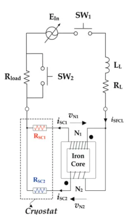
Fig. 1. Schematic configuration of the flux-lock type SFCL using double quench.
본 논문에서 제안한 이중퀜치를 이용할 수 있는 자 속구속형 초전도한류기의 구조를 그림 1에 도시하였 다. 그림 1에서 보는 바와 같이 자기적으로 결합된 두 개의 병렬권선에 각각 초전도소자가 직렬로 연결된 구 조이다. 병렬로 연결된 두 개의 권선은 가극 또는 감 극으로 결선이 가능하며, 본 논문에서 검토한 감극결선 한 경우에는 두 권선의 인덕턴스값이 같지 않도록 설 계해야 이중퀜치동작이 가능하게 된다.
동작원리는 평상시에는 병렬연결된 두 개의 권선에
서 발생되는 자속이 서로 상쇄되어 두 개의 권선에 영 전압이 유기되지만, 단락사고로 고장전류가 유입되어 인던턴스가 작은 권선에 큰 전류가 흘러 직렬연결된 초전도소자가 퀜치로 인해 저항이 발생하면 두 개의 권선에서 발생되는 자속이 상쇄되지 않게 되고 두 개 의 권선에 전압이 유기됨으로써 고장전류가 제한된다.
고장발생초기에 고장전류의 과도성분이 클 경우에는 다른 권선에 연결된 초전도소자 또한 임계전류값을 초 과하게 되어 퀜치가 발생하게 되고 두 차례의 퀜치발 생을 통해 고장전류가 제한되게 된다.
2.2 실험 구성 및 실험 방법
Fig. 2. Experimental circuit of the flux-lock type SFCL using double quench.
그림 2는 이중퀜치를 이용한 자속구속형 초전도한류 기의 과도전류제한특성을 모의하기 위한 실험회로 구 성도를 보여준다. 고장직후 고장전류의 크기에 영향을 주는 고장각조건으로 전원전압 투입후(SW
1
투입) 0°와 90°에서 SW2
을 투입시켜 6주기동안 고장을 모의하였 다. 고장을 모의하기 위한 회로를 구성하는 선로 임피던스, 부하저항, 자속구속형 초전도한류기 설계사항은 표 1에 나타내었다.
3. 결과 및 고찰
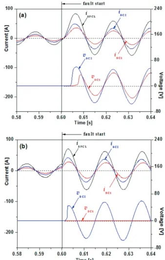
그림 3은 이중퀜치를 이용한 자속구속형 초전도한류 기의 고장각 0°와 90°에서 고장발생시 고장초기 전류제 한특성을 보여준다. 과도전류크기가 큰 0° 고장시는 그 림 3(a)에서 보는 바와 같이 권선수가 작은 두 번째 권선에 연결된 초전도소자(v
SC2
)에서 먼저 퀜치가 발생 하여 전압이 유기된 후 첫 번째 권선에 연결된 초전도 소자(vSC1
)에서 퀜치가 발생하면서 두 차례에 걸쳐 고 장전류가 제한되는 것을 확인할 수 있다. 반면에, 그림 3(b)에 도시한 90° 고장시에는 두 번째 권선에 연결된 초전도소자(vSC2
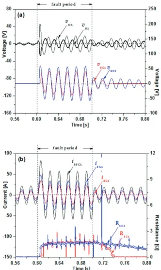
)에서 퀜치가 발생하면서 고장전류가 제한되지만 고장초기 과도전류크기가 작아 첫 번째 권 선에 연결된 초전도소자에는 퀜치가 발생되지 않는 것 을 비교할 수 있다.고장각 0°에서 고장발생시, 측정한 고장기간동안 자 속구속형 초전도한류기의 권선전압(v
N1
, vN2
), 초전도소 자에 유기전압(vSC1
, vSC2
)을 그림 4(a)에 나타내었으며, 전체제한전류(iSFCL
), 각 초전도 소자전류(iSC1
, iSC2
), 초전 도 소자저항들(RSC1
, RSC2
)을 그림 4(b)에 나타내었다.고장초기 큰 과도전류의 크기에 의해 두 권선에 연결 된 초전도소자로 나누어 고장전류가 흐르게 되고 두 번째 권선에 연결된 초전도소자에서 저항(R
SC2
)이 먼저 발생하고 첫 번째 권선에 연결된 초전도소자에서 저항 (RSC1
)이 발생하면서 두 초전도소자들의 전압발생과 함 께 두 차례의 고장전류제한이 진행되는 것을 그림 4(a) 와 그림 4(b)에서 관찰할 수 있다.또한, 고장기간동안 두 개의 초전도소자에서 발생되 는 저항크기는 유사한 크기로 발생되고 있지만, 고장이 제거된 후 초전도상태로 회복되는 영저항값에 도달은 첫 번째 권선에 연결된 초전도소자(R
SC1
)는 바로 영저 항값으로 회복되었지만, 두 번째 권선에 연결된 초전도Experimental circuit for short circuit
Line and load impedance Value Unit
R Line + jX Line R Load
0.42+j0.066 5
Ω Ω Flux-lock type SFCL using double quench Two magnetically coupled windings Value Unit Winding direction
Turn number of winding 1 (N 1 ) Turn number of winding 2 (N 2 )
Subtractive polarity
60 15
Turns Turns
Two HTSC module Value Unit
Material Fabrication type Critical temperature (T C ) Critical current (I C )
YBCO Thin film
87 27
- - K A Table 1. Specifications of experimental circuit with the flux-lock type SFCL using double quench.
Fig. 3. Transient fault current limiting characteristics of the
flux-lock type SFCL using double quench. (a) In case that
fault occurs at 0° fault angle and (b) in case that fault occurs
at 90° fault angle.
소자(R
SC2
)는 일정시간이 소요되는 것을 그림 4(b)에서 관찰할 수 있다.고장각 90°에서 고장발생시 고장기간동안 자속구속 형 초전도한류기를 구성하는 두 개의 권선과 두 개의 초전도소자의 전압파형을 그림 5(a)에, 소자 전류와 소 자에서 발생하는 저항파형을 그림 5(b)에 나타내었다.
그림 5(a)에서 보는 바와 같이 두 번째 권선에 연결된 초전도소자(R
SC2
)에서만 퀜치발생으로 전압(vSC2
)이 발 생하기 때문에 두 번째 권선에 유기되는 전압(vN2
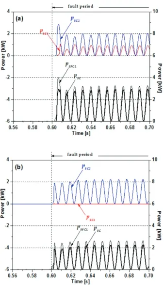
)은 그림 4에서 검토한 고장각 0°시와 달리 크게 유기되면 서 고장전류제한 동작이 이루어지는 것을 비교할 수 있다.고장각 0°와 90°일 때 이중퀜치를 이용한 자속구속 형 초전도한류기를 구성하는 두 개의 초전도소자들의 전력부담(p
SC1
, pSC2
)을 전체 초전도한류기의 전력부담 (pSFCL
)과 비교검토한 결과를 그림 6(a)와 그림 6(b)에 도시하였다. 그림 6(a)의 고장각 0°일 때가 그림 6(b) 의 고장각 90°에서 고장시보다 초전도소자들의 전력부 담증가와 함께 한류기 전체부담이 증가하는 것을 검토 할 수 있었다. 이는 고장초기 고장전류가 클 경우에 고장기간동안 두 개의 초전도 소자들의 퀜치발생에 따 른 전력부담증가로 초전도한류기의 전력부담증가에도 기여하게 되는 것으로 분석할 수 있었다.Fig. 4. Voltage and current waveforms of the flux-lock type SFCL using double quench in case that fault occurs at 0°
fault angle. (a) Voltage waveforms and (b) current waveforms and resistances across each HTSC element.
Fig. 5. Voltage and current waveforms of the flux-lock type SFCL using double quench in case that fault occurs at 90°
fault angle. (a) Voltage waveforms and (b) current waveforms
and resistances across each HTSC element.
4. 결 론
본 논문에서는 자기적으로 병렬 결합된 두 개의 권 선에 직렬로 초전도소자가 개별로 연결한 구조를 갖는 이중퀜치를 이용할 수 있는 자속구속형 초전도한류기 구조를 제안하고 0°와 90° 고장각에서 고장발생시 고장 전류제한특성 분석을 통해 제안한 한류기의 유용성을 검토하였다.
고장초기 과도전류크기가 큰 0° 고장시에는 이중퀜 치에 의해 고장전류제한동작이 이루어지는 것을 모의 실험을 통해 확인하였고, 고장기간동안 각 초전도소자 들의 전력부담과 초전도한류기의 전력부담이 90° 고장 시보다 크게 발생하는 것을 분석할 수 있었다.
REFERENCES