```
1. INTRODUCTION
There have been various research efforts to commercialize HTS (High Temperature Superconductor) power cables with large power capacity and low loss [1, 2].
However, the fault current becomes a serious problem as the power capacity increases, and rapid control of the fault current is important to protect the HTS power cable and other accessories such as circuit breakers and transformers.
To reduce the fault current, various types of SFCLs (Superconductor Fault Current Limiters) have been considered [3]. The SFCL requires high voltage insulation, and large heat generation is accompanied by a restricted space to limit the fault current [4].
The impedance of HTS power cable also increases when the fault current is introduced as the SFCL. However, the HTS power cables are usually designed to bypass the fault current using the low resistive former and suppress the temperature rise. On the other hand, the HTS power cable can limit the fault current by reducing the former area and increasing the impedance within the allowable temperature rise.
Therefore, a SFCL power cable can be used as a HTS power cable during normal operation and it can also be used as the SFCL during fault conditions if the impedance variation of the SFCL power cable is properly designed.
The resistive impedance of the SFCL power cable increases by the quench of the conducting layer and the
shield layer. The inductive impedance also increases by the quench of the shield layer. The variation of the resistive impedance at the conducting layer was investigated by the authors and it was shown that the cable former should be designed considering the required resistive impedance and the allowable temperature limit [4, 5]. The resistive impedance of the conducting layer is directly related to the quench of the conducting layer. When the quench occurs at the shield, the inductive and resistive impedance increase via electromagnetic coupling. To investigate the impedance variation by the quench of shield layer itself, the quench of the shield layer should be avoided.
In this study, the resistive and inductive impedance variations by the quench of the shield layer are investigated with a sample cable, which prevents the quench of the conducting layer. In the experiment 10 HTS wires are considered for conducting layer, while 5 HTS wires for shielding layer. To increase the impedance by the quench of the shield layer, an iron cover installed outside the shield layer is considered. By analyzing the experimental results, possible applications of the SFCL power cable are presented.
2. OPERATION CHARACTERISTIC OF SFCL POWER CABLE
The impedance of the SFCL power cable is composed of resistive and inductive components. The resistive impedance of the conducting layer can be easily modeled
Investigation on the inductive and resistive fault current limiting HTS power cable
Sangyoon Lee
a, Jongho Choi
a, Dongmin Kim
a, Yonghyun Kwon
a, Seokho Kim
*, a, Kideok Sim
b, and Jeonwook Cho
ba
Changwon National University, Changwonl, Korea
b
Korea Electrotechnology Research Institute, Changwon, Korea
(Received 9 June 2014; revised or reviewed 24 June 2014; accepted 25 June 2014)
Abstract
HTS power cable bypass the fault current through the former to protect superconducting tapes. On the other hand, the fault current limiting (FCL) power cable can be considered to mitigate the fault current using its increased inductance and resistance.
Using the increased resistance of the cable is similar to the conventional resistive fault current limiter. In case of HTS power cable, the magnetic field of HTS power cable is mostly shielded by the induced current on the shield layer during normal operation.
However, quench occurs at the shield layer and its current is kept below its critical current at the fault condition. Consequently, the magnetic field starts to spread out and it generates additional inductive impedance of the cable. The inductive impedance can be enhanced more by installing materials of high magnetic susceptibility around the HTS power cable. It is a concept of SFCL power cable. In this paper, a sample SFCL power cable is suggested and experimental results are presented to investigate the effect of iron cover on the impedance generation. The tests results are analyzed to verify the generation of the inductive and resistive impedance.
The analysis results suggest the possible applications of the SFCL power cable to reduce the fault current in a real grid.
Keywords: HTS Power Cable, Quench, SFCL, Impedance
* Corresponding author: [email protected]
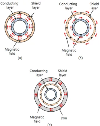
Fig. 1. Operating characteristics of inductive SFCL power cable (a) normal state (b) quench of shield layer without iron (c) quench of shield layer with iron.
by considering the resistance of the cable former and the critical current. However, additional resistive and inductive impedance are generated when considering quench of the shield layer.
During normal operation, the magnetic field of the conducting layer is shielded by the shield layer and the inductive impedance is very small compared with other conventional copper cables. Fig. 1(a) shows the case of normal operation. However, the magnetic field starts to spread out when the fault current is introduced to the conducting layer, and the shield current is limited under its critical current. Fig. 1(b) shows the quench of the shield layer. Therefore, the inductive impedance also increases and it can be further increased by installing an iron cover outside the shield layer [6]. Fig. 1(c) shows the change of the magnetic field according to the inclusion of the iron cover.
TABLE 1 S
PECIFICATIONS OFHTS
WIRE.
Items Value
Superconductor material GdBCO/IBAD
Substrate Hastelloy
Width/Thickness (including copper
plating) 4mm/0.2mm
Critical current 195 A @ 77K, sf
Manufacturer SuNAM
Fig. 2. Cross-section of SFCL cable.
Fig. 3. Schematic diagram and fabricated sample cable.
3. EXPERIMENTAL APPARATUS
A sample SFCL power cable was designed and fabricated to investigate the increased impedance by the quench of the shield layer. To minimize the resistance impedance by the quench of the conducting layer, 10 HTS wires were used for the conducting layer and 5 HTS wires were used for the shield layer. Table 1 describes the specifications of the HTS wire and Fig. 2 shows a schematic diagram of the sample cable. A FRP rod was used as a cable former instead of a copper former.
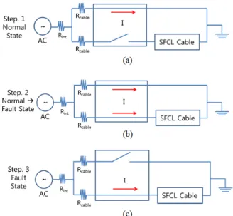
Fig. 3 shows the fabricated SFCL power cable used for the test. The length of the cable is 2 m. A voltage controlled AC power supply and a circuit breaker were used to simulate the fault state. A constant AC voltage source was applied to confirm the current limiting effect by the increased impedance. Fig. 4 shows the experimental steps using a circuit breaker and a timer; (a) is the normal state, (b) is the intermediate state for fault current, and (c) describes the fault state.
4. EXPERIMENTAL PROCEDURE AND RESULTS
All experiments were performed in liquid nitrogen. The inflow fault currents were set by controlling the voltage of the AC power supply without SFCL power cable when the system is at step 3 of Fig. 4. The experiments were performed for the inflow fault current from 250 A
rmsto 2,250 A
rms. The transport current through the SFCL power cable was measured by using rogowskii coil.
The inflow fault current was estimated by assuming zero
impedance of the sample cable. In this case, the impedance
Fig. 4. Experimental steps (a) is normal state (b) is intermediate state for fault current (c) describes the fault state.
Fig. 5. Current limiting results from 2250 A
rmsinflow current to 1580 A
rms.
Fig. 6. Current limiting results for various inflow fault currents.
is composed of the internal impedance(R
int) of the AC power supply and resistance(R
cable) of the connecting cable.
The voltage signals were measured by a fast DAQ system. Fig. 5 presents one of the measured voltage-current graphs, and it shows that the fault current is limited to 1,580 A
rmswhen the estimated inflow fault current is 2,250 A
rmswith iron cover. Fig. 6 shows the limited current corresponding to the inflow fault currents. The fault current was limited more when the iron cover was applied.
5. ANALYSIS OF THE EXPERIMENTAL RESULTS
The fault state was demonstrated by changing a circuit using a circuit breaker in the experiment but changing the circuit in the analysis is impossible and the fault state can be described by changing a resistance of shield layer using an equation (1) for step 3 of Fig. 4, by induced the resistivity of HTS wire can be expressed by (1) [7].
−1
=
n
c c c
I I J
ρ E (1)
Where ρ[Ω-m] is resistivity of HTS wire, E
c[V] is the critical electric field(1uV/cm), J
c[A/m
2] is critical current density and I [A] is conducting layer current.
To investigate the quantitative variation of the resistance and inductive impedance, the measured voltage and current data were analyzed. In the analysis, the voltage and current data of the first cycle after accident were used. First, the RMS (Root Mean Square) of the voltage (V
rms) and the current (I
rms) was calculated by using (2) and (3), because the measured signals are not perfect sine wave. The apparent electric power (P
a) was then calculated by using (4).
dt t T V V
rms1
T( )
0
∫
2= (2)
dt t T I I
rms1
T( )
0
∫
2= (3)
Q P I V
P
a=
rms×
rms=
2+
2(4) Where V(t) [V] and I(t) [A] are the measured voltage and current and P [W] and Q [Var] are the active and reactive power.
Since the active power can be obtained from the measured V and I, as in (4), the resistive impedance R and the inductive impedance X can be obtained using (5), (6), and (7).
∫ ×
=
TV t I t dt P T
0
( ) ( )
1 (5)
I R P
rms
=
2(6)
(a)
(b)
(c)
Fig. 7. Impedance of SFCL power cable (a) total impedance (b) inductive impedance (c) resistive impedance.
2