Superconductivity and Cryogenics
Vol.14, No.4, (2012), pp.36~40 http://dx.doi.org/10.9714/sac.2012.14.4.036
```
Abstract— This paper presents an experimental and numerical study on current limiting characteristics of a fault current controller (FCC). The FCC consists of an AC/DC power converter, a superconducting coil, and a control unit.
Even though some previous researches proved that the FCC could adjust the fault current level, the current limiting characteristics by the superconducting coil should be investigated for design of the coil. In this paper, four kinds of model coils were tested; 1) air core, 2) iron core without any bias, 3) reversely magnetized core (RMC) using permanent magnets, and 4) RMC using an electromagnet. Based on a comparative study, it is confirmed that a RMC by an electromagnet (EM) could increase the effective inductance of the coil. In this paper, a numerical code to simulate the HTS coil with RMC was developed. This code can be applied to design the HTS coil with active reversely magnetized bias coil.
Keywords: Current limiting characteristics, fault current controller, reversely magnetized core, superconducting coil.
1. INTRODUCTION
A paradigm shift of the electric power system, represented by the smart grid, has been proposed and widely researched. Among the huge changes by the smart grid, increasing renewable-energy-based distributed generations (DGs) can be a potential threat on the power stability side, since renewable energy sources are naturally unstable and unpredictable. On the other hand, a real-time monitoring technology can be an opportunity factor [1]. To reflect both threat and opportunity, a fault current controller (FCC) was proposed and experimentally proved [2,3].
While a superconducting fault current limiter (FCL) passively limits a fault current, the FCC can adjust the fault current level to the required value which is pre-determined by considering protection coordination such as relay settings and circuit-breakers. The fault current controlling can be easily achieved by changing firing angle of thyristors [2]. However, the first peak surge current cannot be controlled by this firing angle delay. It only depends on the inductance of the superconducting coil which plays role of a DC reactor. Hence, the efficient method to increase the effective inductance of the coil is needed to reduce the
superconducting wire consumption. As a method to increase the effective inductance, the reversely magnetized core (RMC) with permanent magnets (PMs) was proposed and tested [4]. There have been former researches on reversely magnetized bias (RMB) [5]. In the former research, the RMC technique was adopted to a DC reactor type (bridge-type) FCL. In the research, the fault current was gradually increased during the full fault period. Hence, the RMB coil should have a high inductance to endure the fault. However, in this study, the RMB coil should be working only for first peak current, since a current is controlled by changing the rectifiers’ firing angle in the rest of fault duration.
In this paper, two kinds of RMC were implemented; by using PMs and an electromagnet (EM). The first peak current limitation was investigated by the two kinds of RMC techniques. In addition, a simulation code for a numerical analysis was developed. Comparative studies between the experimental and numerical analysis were also conducted.
2. REVERSELYMAGNETIZEDCORE 2.1. Current Limiting Characteristics of FCC
As proved in previous work [2], a fault current can be adjusted by controlling the firing angle of the rectifiers after the second peak of the current. However, the first peak current should be limited by only an inductance of the HTS coil. Since the instant limiting of fault current is one of most important characteristics of superconducting fault current limiters, even the first peak surge-current must be limited.
To make the higher inductance coil, the longer HTS wire is required. Thus, a study on increasing the effective inductance of the coil during the first peak fault is important for optimal coil design.
2.2. Effectiveness of RMC
The easiest way to enhance the inductance is to use a ferromagnetic core. However, there should be a magnetic saturation in the core, since DC current is supposed to be transported in the HTS coil in normal operation. Therefore, the inserting of an iron-core cannot be a best option. To overcome this saturation problem, a reversely magnetized
Fault Current Limitation by a Superconducting Coil with a Reversely Magnetized Core for a Fault Current Controller
Min Cheol Ahn1 and Tae Kuk Ko2
1Department of Electrical Engineering, Kunsan National University
2School of Electrical and Electronic Engineering, Yonsei University Received 13 November 2012; accepted 23 November 2012
* Corresponding author: [email protected]
Min Cheol Ahn and Tae Kuk Ko
1.37 1.38 1.39 1.40 1.41 1.42 1.43
-150 -120 -90 -60 -30 0 30 60 90 120
150 Line current
Coil current
Current (A)
Time (s)
1.10 1.11 1.12 1.13 1.14 1.15 1.16
-150 -120 -90 -60 -30 0 30 60 90 120 150
Current (A)
Time (s)
Line current Coil current
1.09 1.10 1.11 1.12 1.13 1.14 1.15
-150 -120 -90 -60 -30 0 30 60 90 120 150
Current (A)
Time (s)
Line current Coil current
(a) (b) (c)
Fig. 3. Test results for a DC reactor coil with (a) air-core, (b) iron-core without RMB, (c) RMC using PMs.
bias was applied. The reserve bias was implemented by two different ways; PMs and an EM. The reserve bias helps to cancel out magnetic flux, thus the bias point could be moved down in B-H curve. Hence, the effective inductance can be larger than that of no-bias case when a fault occurs.
3. EXPERIMENTALANALYSIS 3.1. Experimental Setup
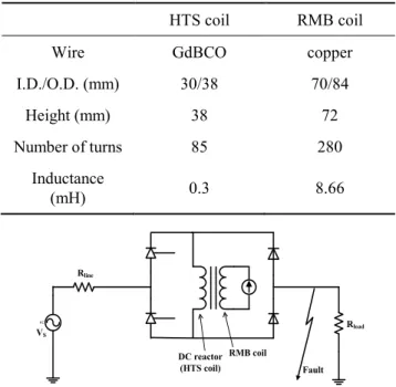
To verify the effectiveness of the first fault current peak reduction by the RMC, four kinds of model coils were tested; 1) air core, 2) iron core without any reverse bias, 3) RMC using PM, and 4) RMC using an EM. Fig. 1 shows the model number 3) and 4). The same iron-core was used for all tests, except for an air-core case. The mean length and cross-sectional area of the core are 0.279 m and 529 mm2, respectively. The measured inductance of coil with iron-core was 1.3 mH. Table I summarizes the specifications of the HTS coil and a RMB coil. Two PMs were used, and the maximum magnetic flux density of each PM was 0.5 T.
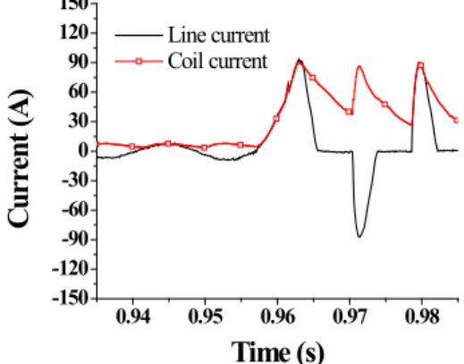
Fig. 2 shows a circuit diagram of the FCC system. Circuit parameters for short-circuit tests are shown in Table II. The line impedance and load resistance are independently varied. The line impedance affects the magnitude of fault current, and the load resistance determines normal operation current. In this study, since the normal operation current makes the initial bias of the iron-core, some tests with various load resistances were conducted.
Fig. 1. Test model coils with RMC; (left) using permanent magnets, (right) using an electromagnet.
TABLEI
SPECIFICATIONS OF HTS COIL AND RMB COIL. HTS coil RMB coil
Wire GdBCO copper
I.D./O.D. (mm) 30/38 70/84
Height (mm) 38 72
Number of turns 85 280
Inductance
(mH) 0.3 8.66
DC reactor (HTS coil)
RMB coil
AC
Fault Rload
Rline
VS
Fig. 2. Test circuit of FCC system with a RMB coil.
TABLEII
SHORT-CIRCUIT TEST PARAMETERS.
Parameter Value
Source voltage (Vs) 36.7 Vrms (52 Vpeak) Line impedance (RLine) 0.3 Ω, 0.57 Ω Load resistance (RLoad) 2 Ω ~ 7 Ω
3.2. Test result 1: Air-core and iron-core w/o bias Fig. 3 shows test result for line impedance of 0.3 Ω and load resistance of 2 Ω. In all test result plots, coil current means the DC reactor-coil-current. In air-core case, the first peak current was 124.6 A as shown in Fig. 3(a). The effective inductance is obviously 0.3 mH as shown in Table I. In case of Fig. 3 (b), which is no-RMB case, the first peak current was 123 A, as almost same as the air-core case.
It obviously shows that the iron-core was saturated by the normal operation current.
37
Fault Current Limitation by a Superconducting Coil with a Reversely Magnetized Core for a Fault Current Controller
3.3. Test result 2: RMC using PMs
Fig. 3 (c) shows fault current limitation by the RMC technique using PMs. In the plot, the first peak current was 100.7 A. Based on a numerical simulation [4], the effective inductance was 1.1 mH, which was 3.67 times larger than that of air-core case. It can be concluded that the RMC using PMs is efficient method to increase the effective inductance. In other words, if we have a target inductance for the FCC system, this RMC makes the wire consumption much less.
Even though the RMC technique using PMs is simple and effective, it cannot consider the time-varying normal operation current because a PM provides almost constant magnetic flux. To observe this uncontrollability, Fig. 4 shows a case with load resistance of 7 Ω. In the plot, the first peak current is 93.3 A. Since the prospective fault current is mainly determined by the line impedance, it is expected that both Fig. 3 (c) case and Fig. 4 case have same fault current. However, the actual peak current value of the 7 Ω load case was 7.3 % lower than that of 2 Ω load case, because the normal operation current was smaller, thus initial bias point was relatively far from the saturation region. It can be said that the RMC using PMs is passive and uncontrollable.
3.4. Test result 3: RMC using an EM
As another method to make a RMC, a copper EM was adopted. Fig. 5 shows the experimental results when the EM was applied. Tests were conducted with a load resistance of 2 Ω and a line impedance of 0.3 Ω. Two plots of Fig. 5 were for two kinds of RMB-coil-current; 5 A and 8 A. The first peak currents were 116.7 A and 109 A, respectively. The effective inductances were 0.55 mH and 0.85 mH. As the RMB coil current increased, the first peak current was reduced.
To observe the controllability of the first peak current in case of RMC using an EM, another set of test was conducted with a load resistance of 5 Ω and a line impedance of 0.3 Ω. In these cases, normal operation current should be smaller than those of 2 Ω cases, thus, the smaller RMB coil current were required. Fig. 6 shows the results of the 5 Ω cases with two kinds of RMB coil currents. In Fig. 6 (a) and (b), the first peak currents were 116 A and 109 A, respectively. Note that the first peak
0.94 0.95 0.96 0.97 0.98 -150
-120-90 -60 -30 0 30 60 90 120 150
Line current Coil current
Current (A)
Time (s)
Fig. 4. Test results for RMC using PMs in case of 7 Ω load resistance.
(a) (b)
1.10 1.11 1.12 1.13 1.14 1.15 1.16 -90
-60 -30 0 30 60 90 120 150
Current (A)
Time (s) Line current Coil current 1.04 1.05 1.06 1.07 1.08 1.09 1.10
-90 -60 -30 0 30 60 90 120 150
Current (A)
Time (s) Line current Coil current
Fig. 5. Test results for RMC using an EM in case of 2 Ω load resistance; (a) RMB coil current of 5A, (b) 8A.
0.79 0.80 0.81 0.82 0.83 0.84 0.85 -90
-60 -30 0 30 60 90 120 150
Current (A)
Time (s) Line current Coil current 1.00 1.01 1.02 1.03 1.04 1.05 1.06
-90 -60 -30 0 30 60 90 120 150
Current (A)
Time (s) Line current Coil current
(a) (b)
Fig. 6. Test results for RMC using an EM in case of 5 Ω load resistance; (a) RMB coil current of 1A, (b) 3A.
currents of Fig. 5 (a) and Fig. 6 (a) were almost same, even though the different RMB coil currents were applied. In addition, results of Fig. 5(b) and Fig. 6 (b) were also almost same. Consequently, the RMC technique using an EM is actively controllable to correspond to time-varying load resistance.
4. NUMERICALANALYSIS 4.1. Simulation model
Even though the effectiveness of the RMC using an EM was proved experimentally in particular cases, a simulation model is needed to design a DC reactor coil by applying this RMC technique.
To analyze the first peak current during the first swing of a fault, the circuit in Fig. 2 can be approximated to the circuit as shown in Fig. 7 (a). The governing equation is (1).
(1) where Vs is applied as a sinusoidal wave and the initial value of current i is the HTS coil’s normal operation current.
Since the magnetic property of an iron-core is non-linear, the inductance L is a time-varying variable. In order to calculate the inductance, a magnetic circuit as shown in Fig.
7 (b) was used. The reluctance was a magnetic resistance which is a function of the relative permeability as shown in a solid line of Fig. 8. The other plots with markers of Fig. 8 were load lines with HTS coil current of 9.4 A, 21.7 A and 38
Min Cheol Ahn and Tae Kuk Ko
100 A. The current of 9.4 A and 21.7 A were the initial current values with 5 Ω and 2 Ω load, respectively. The effective relative-permeability could be obtained by finding the intersection point in the plot. Then, the effective inductance was calculated by the relative-permeability.
(2)
where Φ is the magnetic flux, A is the cross-sectional area of iron-core, is the reluctance, l is the mean length of the core, N is the number of turns, and μis permeability.
The simulation was conducted based on the finite difference method. The number of steps was 1000. Once the effective inductance was calculated, the ordinary differential equation of (1) was solved by Runge-Kutta method. As a solution of (1), we could get the updated current value, and then the effective inductance was calculated again. The simulation was coded by MATLAB® and the final output plots are the effective inductance and current versus time.
4.2. Simulation result
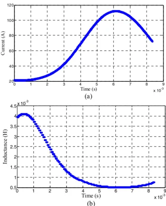
The simulation period was 1/120 second which is corresponding to the first peak current. Fig. 9 shows a simulation result. Fig. 9 (a) shows the simulated current vs.
time, and Fig. 9 (b) shows the calculated inductance vs.
time. The parameters of the simulation were load resistance of 2 Ω and line impedance of 0.3 Ω. As mentioned in section 4.1, the code calculated the time-varying effective inductance and the fault current. The first peak current was 110.8 A in the simulation of Fig. 9 (a). The experimental result was 116. 7 A as shown in Fig. 5 (a).
Fig. 10 summarizes the simulation results, comparing with experimental results. The simulation results mostly well agreed with the experimental ones, particularly in small RMB coil current cases. However, there were also large discrepancy between simulation and experimental ones, in the larger RMB coil current cases. The errors could come from the current source’s limitation, which is used for RMB coil current charging, because the maximum current capacity was 8 A. To find more obvious reasons for this error, some additional tests were required and will be investigated.
Fig. 7. Simulation model circuit diagrams; (a) an electric circuit, (b) a magnetic circuit for calculating the inductance L.
Fig. 8. Relative permeability vs. magnetic flux density.
Fig. 9. Simulation result for the DC reactor coil with RMB coil current of 5 A and 2 Ω load.
Fig. 10. Simulation and test results.
0 1 2 3 4 5 6 7 8 9
x 10-3 0.5
1 1.5 2 2.5 3 3.5 4 4.5 x 10
-3
Time (s)
Inductance (H)
0 1 2 3 4 5 6 7 8 9
x 10-3 20
40 60 80 100 120
Time (s)
Current (A)
(a)
(b)
39
Fault Current Limitation by a Superconducting Coil with a Reversely Magnetized Core for a Fault Current Controller
5. CONCLUSIOIN
In this paper, the fault current limitation characteristics of an HTS coil were investigated when the reversely magnetized core was applied. This coil is supposed to be applied to a fault current controller. Since the fault current level can be controlled by solid-state rectifiers after the first peak current in the FCC, we have concentrated on the first peak current reduction. To make reversely magnetized core, permanent magnets and a copper electromagnet were applied. Based on experimental and simulation results, we summarize the conclusions as follows;
(1) The RMC technique is quite effective to increase the effective inductance.
(2) The RMC can be implemented using PMs. This RMC is simple and efficient, but uncontrollable.
(3) The RMC using an EM is also properly working.
This method is active, thus the first peak currents could be controlled to be almost same in various load resistance cases.
(4) For general design of an HTS coil with RMC using an EM, the numerical analysis was conducted. The simulation code could calculate the time-varying effective inductance with a consideration of non-linear magnetic property of iron-core. Then, the fault current was also calculated using this inductance value.
(5) The simulation results mostly well agreed with the
experimental results in low-RMB-coil current cases.
Some discrepancy between simulation and experimental results were also observed in large-RMB-coil current cases.
ACKNOWLEDGMENT
This paper was supported by research funds of Kunsan National University.
REFERENCES
[1] The smart grid: an introduction, Litos strategic communication for US department of energy, 2008.
[2] M. C. Ahn and T. K. Ko, “Proof-of-concept of a Smart Fault Controller with a Superconducting coil for the Smart Grid,” IEEE Trans. Appl. Supercond., vol. 21, no. 3, pp. 2201-2204, June 2011.
[3] J. Y. Jang, W. S. Lee, J. Lee, Y. J. Hwang, H. C. Jo, M. C. Ahn, K.
Hur, and T. K. Ko, “Performance Evaluation on Fault Current Controller System for the Applications of Smart Grid,
“ Superconductivity and Cryogenics, vol. 14, no. 2, pp. 12-15, 2012.
[4] M. C. Ahn, J. Y. Jang, and T. K. Ko, “Characteristics of an HTS Coil with a Reversely Magnetized Core for the Smart Fault Current Controller,” IEEE Trans. Appl. Supercond., vol. 22, no. 3, pp.
5601905, June 2012.
[5] K. M. Salim, T. Hoshino, M. Nishikawa, I. Muta, and T. Nakamura,
“Preliminary Experiments on Saturated DC Reactor Type Fault Current Limiter,” IEEE Trans. Appl. Supercond., vol. 12, no. 1, pp.
872-875, March 2002.
40