Progress in Superconductivity and Cryogenics
Vol.15, No.4, (2013), pp.26~29 http://dx.doi.org/10.9714/psac.2013.15.4.026
```
1. INTRODUCTION
An increase of the power consumption causes a power shortage and to solve power shortage, transmission capacity in the power grid should be growing. Due to the increase of the transmission capacity, fault current level may increase. This causes circuit breakers installed in the grid do not appropriately operate because the fault current can exceed rated capacity of circuit breakers [2]. Therefore, installed circuit breakers need to be replaced with higher capacity devices. However, it has difficulty with cost problem. To overcome this problem, decreasing level of the fault current in the grid by installing SFCL has been actively considered.
SFCL does not affect the power grid system during normal operation, however once the fault occurs, the fault current is limited by the SFCL due to generated resistance by quench of a superconducting coils. Using the SFCL in grid system has an advantage that existing circuit breakers do not need to be replaced since SFCL makes the fault current lower [3].
However, SFCL has following demerits. SFCL limits the fault current applying a quench characteristics of the superconducting coils and using the quench characteristics can damage of the superconducting coils. Also, the superconducting coils should have enough recovery time to maintain superconducting state and the recovery time is supposed to be shorter than the reclosing time of protection devices in the grid system for appropriate power supply. In
addition, much more cost of cooling system is needed because the quench of the superconducting coils are causing the Joule heat, so that coolant is more consumed.
To complement the demerits of SFCL, this paper suggests a hybrid type SFCL consists of a resistive type superconducting coil and two thyristors. For analysis of SFCL, we designed the resistive type superconducting coil and a thyristor control circuit for control the fault current.
To supplement the demerits of SFCLs, this paper suggests the hybrid type SFCLs which consist of the resistive type superconducting coil with thyristors. For analysis of SFCLs, we designed the resistive type superconducting coil and the thyristor control circuit for control the fault current. Technology that control the fault current using thyristors was already conducted and suggested through our previous works [1], [4]. In this paper, we propose the concept of the hybrid type SFCL, and then compare the hybrid type SFCL with the resistive type SFCL based on circuit simulation.
2. OPERATING PRINCIPLE
Fig. 1 shows the schematic diagram of the hybrid type SFCL.
Before the fault occurs, phase angle of thyristors is zero and thyristors act as diodes. When the fault occurs, the current that flows in coil is rapidly increased. At this time, the superconducting coil limits first peak of fault current and a control circuit calculates proper phase angle of thyristor according to the control algorithm. After the half
A numerical study on the feasibility evaluation of a hybrid type superconducting fault current limiter applying thyristors
Seokho Nam, Woo Seung Lee, Jiho Lee, Young Jin Hwang, and Tae Kuk Ko* Yonsei University, Seoul, Korea
(Received 31 July 2013; revised or reviewed 17 December 2013; accepted 18 December 2013)
Abstract
Smart fault current controller (SFCC) proposed in our previous work consists of a power converter, a high temperature superconducting (HTS) DC reactor, thyristors, and a control unit [1]. SFCC can limit and control the current by adjusting firing angles of thyristors when a fault occurs. SFCC has complex structure because the HTS DC reactor generates the loss under AC. To use the DC reactor under AC, rectifier that consists of four thyristors is needed and it increases internal resistance of SFCC. For this reason, authors propose a hybrid type superconducting fault current limiter (SFCL). The hybrid type SFCL proposed in this paper consists of a non-inductive superconducting coil and two thyristors. To verify the feasibility of the proposed hybrid type SFCL, simulations about the interaction of the superconducting coil and thyristors are conducted when fault current flows in the superconducting coil. Authors expect that the hybrid type SFCL can control the magnitude of the fault current by adjusting the firing angles of thyristors after the superconducting coil limits the fault current at first peak.
Keywords : SFCC, hybrid type, SFCL, thyristor, non-inductive superconducting coil
* Corresponding author: [email protected]
Seokho Nam, Woo Seung Lee, Jiho Lee, Young Jin Hwang, and Tae Kuk Ko
Line Resistance
Superconducting Coil (Non-inductive type)
Thyristor 1
Rload AC
Power Supply
Thyristor Control
circuit Thyristor 2 Variable
Resistance
Fig. 1. Schematic diagram of the hybrid type SFCL.
Current
degree
α α
degree
π+α
turn off
turn on
Fig. 2. Performance principle of the thyristor control circuit.
TABLEI
DESIGN PARAMETER VALUES OF THE RESISTIVE TYPE SUPERCONDUCTING COIL
Parameter Value
Rn 2 Ω
TF 0.01 s
to 0.1 s
cycle passed at the first peak, a control unit supplies gate signals to thyristors. These gate signals can control the level of the fault current by adjusting firing angle. It should be selected in a range of 0° to 180° to limit the first peak of the fault current. Fig. 2 shows the operating characteristics of a thyristor when phase angle is α.
3. SFCL DESIGN AND SIMULATION SETUP 3.1. Resistive Type Superconducting Coil
The resistive type superconducting coil is designed for simulations of the hybrid type SFCL. The superconducting coil is designed with the non-inductively wound coil.
When fault current flows in the superconducting coil, value of resistance is as in [3].
0 ) ( t
R (t
o> t) (1)
1 exp ( ) /
1/2)
( t R
nt t
oT
FR (t
o≤ t < t
1) (2) )
( )
( t b
1a
1t t
1R (t
1≤ t < t
2) (3) )
( )
( t b
2a
2t t
2R (t
2≤ t) (4) In equation (1)-(4), R
nis a resistance when quench occurs, T
Fis time constant. t
o, t
1, t
2mean respectively fault occurring time, 1
strecovery time, 2
ndrecovery time. a
1and a
2mean velocity of recovery time, b
1is standard resistance of 1
strecovery time, and b
2is standard resistance of 2
ndrecovery time. However, the superconducting coil used in the proposed hybrid type SFCL is designed in consideration of only equation (1)-(2) since the cooling conditions are not be considered. Design parameters for the superconducting coil are organized in Table 1.
3.2. Thyristor Control Circuit
The control circuit should control fault current by controlling the phase angle of thyristors through the gate signals. Therefore, calculating the proper phase angle is very important factor in development of the proposed hybrid type SFCL. Through previous works, the thyristor control circuit was studied and this type use four thyristors, however, the hybrid type SFCL uses only two thyristors and it is relatively easier to design the controller since the hybrid type SFCL has more simple structures than the
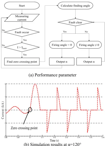
Start
Measuring current
Fault occur
I > Ilimit
Find zero crossing point
Calculate finding angle
Fault clear
Firing angle = 0 Firing angle ≠ 0
Output α Output α
Yes
Yes
Yes No
No
No
(a) Performance parameter
0.08 0.09 0.1 0.11 0.12 0.13 0.14 0.15 0.16
-2 -1 0 1 2
Time (s)
Current (kA)
Zero crossing point
(b) Simulation results at α=120°
Fig. 3. Designed thyristor control circuit.
A numerical study on the feasibility evaluation of a hybrid type superconducting fault current limiter applying thyristors
TABLEII
SPECIFICATIONS OF SIMULATION PARAMETERS
Parameter Value
Input voltage 4kVpeak, 60Hz
Line resistance 2 Ω
Load resistance 13 Ω
Phase angle 0°, 60°, 90°, 120°, 150°
Measure the current
I > IC
Superconducting Quenchcoil
Thyristor controller Output the specific firing angle
gate pulse (α)
Fault clear
Superconducting Recoverycoil
Thyristor controller Output the specific firing angle
gate pulse (zero) Yes
Yes No
No
Fig. 4. Flow diagram of hybrid type SFCL.
0.08 0.1 0.12 0.14 0.16 0.18 0.2
-2 -1.5 -1 -0.5 0 0.5 1 1.5 2
w/o SFCL w/ Hybrid SFCL
Current (kA)
Time (s)
Fig. 5. Simulation results of with and without hybrid type SFCL at α=120°.
thyristor control circuit of SFCC. Parameter and simulation result of designed control circuit is shown at Fig.
3. To output the appropriate phase angle after fault, control circuit should find the zero crossing point. Control circuit supplies gate signals to thyristors based on this point.
3.3. Simulation Setup
To simulate the hybrid type SFCL, a commercialized simulation parameters are shown in table II. As normal state (I < I
limit), system of the hybrid type SFCL has only
line resistance and load resistance. I
limitis critical current of the superconducting coil. However, line current increases abruptly after short-circuit fault and resistance of the superconducting coil is increased as shown in equation (2).
At the same time, control circuit calculates the phase angle and then specific firing angle outputs to thyristors.
These parameters are shown at Fig. 4.
4. SIMULATIONS AND ANALYSIS
To evaluate operating characteristics of the hybrid type SFCL, the simulation results of with and without the hybrid type SFCL are compared. Compared simulation results are shown at Fig. 5. After short-fault occurs at the time denoted as 0.1 s, it is maintained for 0.1 s. The first peak current is 2 kA when an SFCL.
-3 -2 -1 0 1 2 3 -3 -2 -1 0 1 2 3 -3 -2 -1 0 1 2 3
-3 -2 -1 0 1 2 3
-3 -2 -1 0 1 2 3
60 degree
90 degree
120 degree
150 degree
-3 -2 -1 0 1 2 3
w/o SFCL
Only SC 3
-3 0 3
-3 0 3
-3 0 3
-3 0 3
-3 0 3
-3 0
0.08 0.09 0.1 0.11 0.12 0.13 0.14 0.15 0.16
0.08-3 0.09 0.1 0.11 0.12 0.13 0.14 0.15 0.16
Fault
Time (s)
Current (kA)
Fig. 6. Line currents according to phase angle of the hybrid type SFCL.
0 3 6 9 0 3 6 9
0 3 6 9
0 3 6 9
0 3 6 9
0 3 6 9
w/o SFCL
Only SC
60 degree
90 degree
120 degree
150 degree
0.08 0.09 0.1 0.11 0.12 0.13 0.14 0.15 0.16
Time (s)
3 6
Energy loss (MW)Energy
Fig. 7. Energy when fault occurs of the hybrid type SFCL
according to phase angle.
Seokho Nam, Woo Seung Lee, Jiho Lee, Young Jin Hwang, and Tae Kuk Ko
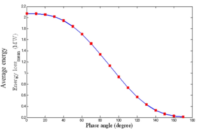
Average energy
Fig. 8. Average energy during fault according to phase angle.
The first peak current is 2 kA when a SFCL does not exist, however, it is suppressed under 1.25 kA by the hybrid type SFCL. First peak of fault current is reduced by the superconducting coil. After the first peak, the fault current is reduced by interaction of the superconducting coil and the thyrisitor control circuit.
Even though the thyristor control circuit is supposed to calculate the proper phase angle in real state, the angle 0°
to 180° are selected to prove a function of the fault current controlling. Simulation results as shown in Fig. 6, the target levels of current are controlled by variation the controlling the phase angle of thyristor can reduce the energy that is generated by the fault current.
5. CONCLUSION
This paper proposes a hybrid type SFCL to limit fault current. The hybrid type SFCL consists of a resistive type superconducting coil and a thyristor control circuit.
Performance characteristics of the hybrid type SFCL are limiting the fault current by interaction of a superconducting coil and the thyristor control circuit.
The first peak of fault current is limited by the superconducting coil and the fault current except for the first peak is controlled by thyristors that can control the current by adjusting firing angle. However, characteristic on the recovery of the superconducting coil can’t be confirmed because cooling conditions are not considered.
However, through the waveform of simulation results, it can confirm that the fault current is limited by the thyristor controller. Interaction of the superconducting coil and the thyristor control circuit should reduce the load of the superconducting coil. Fault current cannot flow in the hybrid type SFCL during turn-off time of thyristors, turn-off time can help the superconducting coil to recover after fault clear.
It is expected that thyristor controller reduces the impact of the superconducting coil and decreases the recovery time of the superconducting coil after quench. Also, usage of superconducting wire and cooling costs can be reduced.
For the practical verifications, many other characteristics of the superconducting coil like the cooling performance, the recovery performance, and the variable resistance should be considered.
ACKNOWLEDGMENT
This work was supported by the Power Generation &
Electricity delivery of the KETEP grant funded by the Korea government Ministry of Trade, Industry & Energy (No. 20111020400340).
EXAMPLE REFERENCES
[1] M. C. Ahn, T. K. Ko, “Proof-of-concept of a Smart Fault Controller with a Superconducting coil for the Smart Grid,” IEEE Trans. Appl.
Supercond., vol. 21, no. 3, pp. 2201-2204, 2011.
[2] L. Ye, L. Lin, K. P. Juengst, “Application Studies of Superconducting Fault Current Limiters in Electric Power Systems,” IEEE Trans. Appl. Supercond., vol. 12, pp. 900-903, 2002.
[3] J. M. Ahn, J. S. Kim, J.F. Moon, S. H. Lim, J.C. Kim, “Analysis on the Protective Coordination in Power Distribution System with Superconducting Fault Current Limiter,” Trans. KIEE, vol. 57, No.
5, pp. 755-760, 2008.
[4] J. Y. Jang, W. S. Lee, J. Lee, Y. J. Hwang, H. C. Jo, M. C. Ahn, K.
Hur, T. K. Ko, “Performance evaluation on Fault Current Controller System for the Applications of Smart Grid,” Journal of the Institute of Applied Superconductivity and Cryogenics, vol. 14, No. 2, pp.
1-5, 2012.
[5] J. A. Waynert, H. J. Boenig, C. H. Mielke, J. O. Willis, and B. L.
Burley, “Restoration and testing of an HTS fault current controller,”
IEEE Trans. Appl. Supercond., vol. 13, pp. 1984-1987, 2007.
[6] Muhammad H. Rashid, Power electronics, Pearson Prentice Hall, Third Edition, 2005.