Kor. J. Mater. Res.
Vol. 22, No. 2 (2012)
91
†Corresponding author
E-Mail : [email protected] (W. -C. Oh)
Photocatalytic Performance of ZnS and TiO
2Supported on AC Under Visible Light Irradiation
Ze-Da Meng, Sun-Bok Cho, Trisha Ghosh, Lei Zhu, Jong-Geun Choi, Chong-Yeon Park and Won-Chun Oh*
†Department of Advanced Materials Science & Engineering, Hanseo University, Seosan-si, Chungnam-do 356-706, Korea
(Received January 9, 2012 : Received in revised form February 7, 2012 : Accepted February 7, 2012)
Abstract
AC and ZnS modified TiO2 composites (AC/ZnS/TiO2) were prepared using a sol-gel method. The composite obtained was characterized by Brunauer-Emmett-Teller (BET) surface area measurements, X-ray diffraction (XRD), energy dispersive X-ray (EDX) analysis, scanning electron microscope (SEM) analysis, and according to the UV-vis absorption spectra (UV-vis). XRD patterns of the composites showed that the AC/ZnS/TiO2 composites contain a typical single and clear anatase phase. The surface properties as observed by SEM present the characterization of the texture of the AC/ZnS/TiO2 composites, showing a homogenous composition in the particles showing the micro-surface structures and morphology of the composites.The EDX spectra of the elemental identification showed the presence of C and Ti with Zn and S peaks for the AC/ZnS/TiO2 composite. UV-vis patterns of the composites showed that these composites had greater photocatalytic activity under visible light irradiation. A rhodamine B (Rh.B) solution under visible light irradiation was used to determine the photocatalytic activity. The degradation of Rh.B was determined using UV/Vis spectrophotometry. An increase in the photocatalytic activity was observed.
From the photocatalytic results, the excellent activity of the Y-fullerene/TiO2 composites for the degradation of methylene blue under visible irradiation could be attributed to an increase in the photo-absorption effect caused by the ZnS and to the cooperative effect of the AC.
Key words
ZnS, TiO2, visible light, UV-Vis, Rh.B.1. Introduction
Semiconductor oxides have been widely used in optical coating and microelectronics devices, the application to purify contaminants in air and water has been recognized recently.
1-4)Photocatalytic reactions of semiconductors such as splitting of water and decomposition of waste materials have received special attention because of their possible application to the conversion of solar energy into chemical energy and pollution control using solar energy.
5,6)In these investigations, various semiconductor materials such as TiO
2, CdS, ZnS, ZnO and WO
3have been employed to study photocatalytic reduction of pollution in water,
7-11)among which TiO
2was proved to be the most efficient photocatalyst due to its exceptional optical, electronic properties, chemical stability, non-toxicity, and low cost.
12-14)TiO
2shows the highest quantum yield among the popular semiconductors. However, in many cases, the photocatalytic activity of TiO
2is not enough to be useful for industrial purposes.
15-17)The general photocatalytic process of a semiconductor
involves the formation of photoinduced electrons at the conduction band and holes at the valence band, and the subsequent chemical reactions with the surrounding media after photostimulated charges move to the powder surface.
In this way, water can be split into hydrogen and oxygen, and organic pollutants in water or gas can be effectively decomposed or purified. Thus, an efficient photocatalytic process over a semiconductor demands the high mobility for photoinduced electron-hole separation and for their transportation in crystal lattice, which would lower the probability for electron-hole recombination.
18-20)ZnS is an important II-VI semiconductor and can be
applied in cathode-ray tubes (CRTs),
21)luminescence mater-
ials,
22)infrared windows,
23)and photocatalysis.
24-26)In recent
years, ZnS nanocrystals (NCs) have been extensively
studied due to their unique properties and are reported to
have potential as photocatalysts in environmental contam-
inant elimination, CO
2reduction, and H
2evolution.
27,28)For the sake of improving the photocatalytis efficiency of
ZnS or TiO
2, nanoscale ZnS coupled TiO
2photocatalyst
have attracted a great deal of attention for potential appli-
cations such as purification of water or organic dyes.
29,30)However, as other powder photocatalysts, ZnS/TiO
2nano-
particles have some disadvantages, such as low photoca-
talysis efficiency in the visible light region, low utilization rate in practical applications owing to the fact that the generated electron/hole (e
−/h
+) pairs are easily recombined, meanwhile there are some dispersion problems because this nanoparticles are easy to cohere. Thus one way of improving these defects is choosing an appropriate catalyst support.
Active carbon (AC) is an excellent alternative because it can concentrate pollutants through adsorption around loaded TiO
2, leading to an increase in the degradation of pollutants.
31)Additionally, the interaction between the pollutants and the surface of the AC-TiO
2was enhanced to promote further degradation.
32)Consequently, the AC/
TiO
2is a promising photocatalyst with the prospective potential for industrial applications.
33)In the present work, the AC/ZnS/TiO
2photocatalyst was prepared from the sol-gel method and the photocatalytic activity for Rh.B solution was investigated under visible light irradiation. The effect of composition will be tested to clarify the mechanism of charge separation process. X-ray diffraction (XRD), scanning electron microscopy (SEM) and energy dispersive X-ray (EDX) spectroscopy were used to characterize the new complexes.
2. Experimental Procedure 2.1 Materials
All chemicals were used as received without further purification. To obtain active carbon, a coconut-based pre- cursor char purchased from Hanil Green Tec was used (Korea). The coconut shell was pre-carbonized first at 773 K, and then activated by steam diluted with nitrogen in a cylindrical quartz tube at 1023 K for 30 minutes. This AC was washed with deionized water and dried overnight in a vacuum drier at over 683 K.
The titanium (IV) n-butoxide (TNB, C
16H
36O
4Ti) used as the titanium source for the preparation of the AC/ZnS/
TiO
2composites was reagent-grade and purchased from Acros Organics (USA). Zinc Chloride (ZnCl
2) and sodium sulfide·5-hydrate (Na
2S·5H
2O) were used for the prepar- ation of ZnS supplied by Daejung Chemicals & Metals Co., Ltd, Korea and Yakuri Pure Chemicals Co., Ltd, Japan, respectively. Rhodamine B (Rh.B C
28H
31ClN
2O
3) was pur- chased from Samchun Pure Chemical Co., Ltd, (Korea).
2.2 Preparation of AC/ZnS composites
These ACs were washed with deionized water and dried for 24 h at ambient temperature. ACs were pulverized by pulverizer. 20 g of AC materials were ball milled for 48 h at room temperature in a laboratory tumbling ball mill, and then the mechano-chemically carbon materials were ob- tained using a laboratory Pulverisette 6 mono-planetary high energy mill (Idar-Oberstein, Frisch, Germany) for 1 h
with ZrO
2ball (1 mm × 300 g). H
2SO
4and H
3PO
4mixed solution (volume ratio of 70:30, solution A) was used to oxidize the AC particles. 10 g pulverized AC were mixed with 100 ml solution A, stirring 7-8 hours and flush with distilled water for 3 times and dried at 323 K. Oxidized AC were formed.
For ZnS coating, the detailed information of AC/ZnSs (Zn
2+-S
2−refluxing) preparation is described as follows: 30 mg ACs were dispersed in 50 mL of ZnCl
2solution with continuous stirring for 30 mins, and then a stoichiometric amount of 30 ml 2.59 mmol Na
2S solution was prepared separately and injected dropwise into the above mixture with continuous stirring for 3h at 343K. After that, they obtained suspension was heated and refluxed for another 4 h under stirring. The final products were filtered and washed repeatedly with distilled water and ethanol and then vacuum dried at 333K.
2.3 Preparation of AC/ZnS/TiO
2composites
AC/ZnS was prepared using pristine concentrations for the preparation of AC/ZnS/TiO
2composites. AC/ZnS pow- der was mixed with 3 ml TNB solution. The mixture was homogenized under reflux at 343 K for 3 hour, while being stirred in a vial. After stirring, the solution trans- formed to AC/ZnS/TiO
2gels and heat treated (N
2atmos- phere) at 773 K to produce the AC/ZnS/TiO
2composites.
2.4 Characterization of AC/ ZnS/TiO
2compounds XRD (Shimata XD-D1, Japan) was used for crystal phase identification and to estimate the anatase ratio of TiO
2and estimate the crystal phase of ZnS. The XRD patterns were obtained at room temperature using Cu K α radiation. SEM (JOEL, JSM-5200, Japan) was used to observe the surface state and porous structure of the AC/ZnS/TiO
2composites.
The elemental composition of the AC/ZnS/TiO
2com- posites was examined by EDX. SEM was used to observe the surface state and structure of AC/ZnS/TiO
2composites using a scanning electron microscope (JSM-5200 JOEL, Japan). The Brunauer-Emmett-Teller (BET) surface area was determined by N
2adsorption measurements at 77 K (Monosorb, USA).
2.5 Photocatalytic tests
A specified quantity of the photocatalyst composite was added to a 100 ml Rh.B solution. The reactor was placed in the dark for 2 hours to allow the maximum adsorption of Rh.B molecules to the photocatalyst composite particles.
In all experiments, the initial concentration of the Rh.B
was 1 × 10
−5mol/L, and the amount of the photocatalyst
composite was 0.01 g/(100 ml solution). After adsorption,
the photodecomposition of the Rh.B solution was per-
formed under visible light in a dark-box to ensure that the
reactor was irradiated by a single light source. The visible
light source used was an 18 W lamp with the main emis- sion wavelength at 460 nm. Visible light irradiation of the photoreactor was performed for 10 min, 30 min, 60 min, 90 min and 120 min. The experiments were performed at room temperature. In the process of Rh.B degradation, a glass reactor was used and the reactor was placed on a magnetic churn dasher. Samples were then withdrawn regu- larly from the reactor and the dispersed powders were removed by a centrifuge. The Rh.B concentration in the solution was then determined as a function of the irradia- tion time from the change in absorbance at a wavelength of 560 nm. After treatment with the centrifuge the cen- trifugalizations were analyzed using a UV-vis spectropho- tometer.
3. Results and Discussion
3.1 Elemental analysis of the preparation
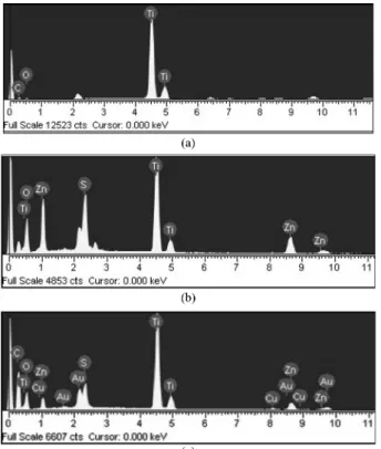
Fig. 1 shows the EDX patterns of the AC/TiO
2(a), ZnS/
TiO
2(b) and AC/ZnS/TiO
2(c). The elemental composition
of these samples was analyzed and the characteristic elements were identified. Fig. 1 shows strong K α and Kβ peaks from Ti at 4.51 and 4.92 keV, whereas a moderate K α peak for O appears at 0.52 keV.
34)In addition to the above peaks, Zn and S was also observed. Fig. 1 presents the quantitative microanalysis of C, O, Ti, Zn and S as the major elements for the composites by EDX. Table 1 lists the composition ratios of the samples. There were some small impurities, which are believed to have been introduced from the unpurified AC or ZnCl
2and Na
2S. In the case of most samples, tungsten, carbon and titanium were present as major elements with small quantities of oxygen in the composite (shown in Table 2).
3.2 Surface characteristics of the samples
Fig. 2 shows the SEM images of the micro-surface structures and the morphology of the compounds. The TiO
2and ZnS particles were coated uniformly over the AC surface, which led to an increase in nanoparticle size.
Zhang et al. reported that a good dispersion of small particles could provide more reactive sites for the reactants than aggregated particles.
35)The surface roughness appears to be high due to some grain aggregation. We cannot find AC particles from the SEM image, this is because the content of AC is so small (show in Table 2). Figs. 2(a), (b)
Fig. 1. EDX elemental microanalysis for (a) AC/TiO2, (c) ZnS/TiO2 and (d) AC/ZnS/TiO2.
Table 1. Nomenclature of samples prepared with photocatalysts.
Preparation method Nomenclatures AC + MCPBA + 3 ml TNB AC/TiO2 2.59 mmol Na2S·5H2O + ZnCl2+ 3 ml TNB ZnS/TiO2
AC + Na2S·5H2O + ZnCl2+ 3 ml TNB AC/ZnS/TiO2
Fig. 2. SEM images of (a) AC/TiO2, (b) ZnS/TiO2 and (c) AC/ZnS/
TiO2.
and (c) show the SEM images of AC/TiO
2, ZnS/TiO
2and AC/ZnS/TiO
2, respectively. The level of aggregation in- creased with an increasing amount of addition. Comparing Figs (a), (b) and (c), we can find that when TiO
2was added, the aggregation became strong. TiO
2can enhance aggregation.
Table 2 lists the BET surface areas of the samples. The BET surface areas of pristine TiO
2, as well as the prepared AC/TiO
2, ZnS/TiO
2and AC/ZnS/TiO
2, were 18.95 m
2/g, 83.25 m
2/g, 32.20 m
2/g and 52.11 m
2/g, respectively. The TiO
2and ZnS particles were introduced to the pore of the AC, which decreased the BET surface area. The AC/TiO
2sample had the largest area, which can affect the adsorption reaction. The BET surface area of the photocatalyst AC/
ZnS/TiO
2was decreased by 37.40% when AC/TiO
2par- ticles were doped by ZnS. This is because ZnS particles fill the pores of the AC/TiO
2particles,
36)thereby reducing the pore size and pore volume of AC/TiO
2particles (showed in Table 2).
3.3 Structural analysis
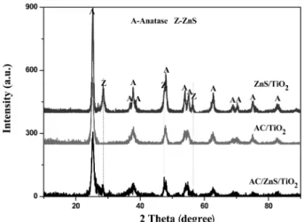
Fig. 3 shows XRD patterns of the AC/TiO
2, ZnS/TiO
2and AC/ZnS/TiO
2composites. After heat treatment at 873 K, major peaks were observed at 25.3
o, 37.9
o, 48.0
o, 53.8
o, 54.9
o, and 62.5
o(2 θ), which were assigned to the (101), (004), (200), (105), (211), and (204) planes of anatase, indicating that the prepared TiO
2is anatase. These results suggest that AC/ZnS/TiO
2also has a pure anatase phase structure with the current preparation conditions. The XRD
pattern shows the characteristic peaks of ZnS. while (111), (220), and (311) crystal planes are originated from the cubic ZnS phase (JCPDS files, No. 5-0566, 77-2100 and 02-0564). The peaks of TiO
2were also observed in the XRD pattern of AC/ZnS/TiO
2compound at 37.9
o(2 θ). In the ZnS/TiO
2and AC/ZnS/TiO
2composite’s XRD pattern the intensity of the peaks about TiO
2was decreased. This is because of the content of TiO
2was decreased, and the peaks of ZnS have affect TiO
2peak. There are few other peaks which are believed to have been introduced from the unpurified Na
2S·5H
2O, ZnCl
2and TNB.
37,38)3.4 UV-vis diffuse reflectance spectroscopy
The diffuse reflectance UV-vis absorption spectra of the different samples are presented in Fig. 4. As expected, we can find TiO
2, ZnS/TiO
2, AC/TiO
2and AC/ZnS/TiO
2com- posites have great absorption at ultraviolet region, TiO
2shows the characteristic spectrum with its fundamental absorption sharp edge rising at 400 nm (Eg = 3.2 eV). On the other hand, ZnS/TiO
2, AC/TiO
2and AC/ZnS/TiO
2composites have good absorption at the visible region, this is also means that these composites has greater photo- catalytic activity under visible light irradiation. Due to ZnS nano particles can effectively absorb light and trap elec- trons on the conduction band, so ZnS/TiO
2has good ad- sorption at visible region. Compared with TiO
2and ZnS/
TiO
2, it is noticeable that there is an obvious correlation between the AC/TiO
2, AC/ZnS/TiO
2composites and the
Fig. 4. Diffuse reflectance UV-vis spectra of pure TiO2, AC/TiO2, ZnS/TiO2 and AC/ZnS/TiO2.
Table 2. EDX elemental microanalysis and BET surface area.
Sample name C (%) O (%) Zn S Ti (%) Impurity (%) BET (m2/g)
TiO2 _ _ _ _ 99.99 0.01 18.95
AC/TiO2 20.72 44.11 _ _ 34.05 1.12 83.25
ZnS/TiO2 _ 31.67 27.66 7.67 21.59 0.04 32.20
ZnS/AC/TiO2 45.36 26.53 6.19 2.67 18.51 0.74 52.11
Fig. 3. The XRD patterns of AC/TiO2, ZnS/TiO2 and AC/ZnS/TiO2.
UV-vis spectrum change. These observations might suggest an increase of surface electric charge of the oxides in the composite catalysts due to AC introduction, which may lead to modifications of the fundamental process of electron/hole pair formation while applying visible irradiation.
39,40)3.5 Photocatalytic activity of samples
Fig. 5 shows the time series of Rh.B degradation using AC/TiO
2, ZnS/TiO
2and AC/ZnS/TiO
2under visible light irradiation. The spectra for the Rh.B solution after visible light irradiation show the relative degradation yields at dif- ferent irradiation times. The decrease in dye concentration continued with an oppositely gentle slope, which was due to visible light irradiation. The concentration of Rh.B was 1.0 × 10
−5mol/l, the absorbance for Rh.B decreased with increasing visible light irradiation time. Moreover, the Rh.B solution increasingly lost its color, and the Rh.B concen- tration continued to decrease. Two steps are involved in the photocatalytic decomposition of dyes; the adsorption of dye molecules and degradation. After adsorption in the dark for 2 hours, the samples reached adsorption-desorption equilibrium. In the adsorptive step, AC/TiO
2, ZnS/TiO
2and AC/ZnS/TiO
2composites showed different adsorptive effects with AC/TiO
2having the best adsorptive effect. The ad- sorptive effect of pure TiO
2was the lowest. AC/TiO
2has the largest BET surface area, which can enhance the adsorptive effect. In the degradation step, the AC/TiO
2, ZnS/TiO
2and AC/ZnS/TiO
2composites showed a good degradation effect. A comparison of the decoloration effect of the catalysts showed that AC/ZnS/TiO
2composites have best degradation effect, which is due to the synergistic reaction of ZnS, AC and TiO
2.
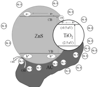
Fig. 6 is the schematic diagram of the separation of the photogenerated electrons and holes on the photocatalytic interface. Both the minimum conduction band and the maximum valence band of ZnS lie above those of TiO
2;
therefore the electrons excited to the conduction band of the TiO
2would transfer to the ZnS, whereas the holes generated in the valence band in the TiO
2prefer an op- posing transfer to the ZnS. Charge carriers separated in different semiconductors effectively reduce the chance of electron-hole pair recombination and prolong their lifetime, thus increasing their quantum efficiencies. In addition, the working range of the wavelength is extended to a visible region due to reduce of the band gap from ZnS and TiO
2, further enhancing the efficiency of the solar energy tran- sition. Synergistic cooperation of these effects enables the ZnS/TiO
2system to exhibit great potential for solar cell and photocatalysis applications.
41-44)AC acts as the adsorb effect, and increases the surface area of the compounds which can increase the adsorption effect for samples, adsorbing more O
2and dye molecules, and ensuring these systems take full advantage of yield oxidizing species. The positive holes in the valence band can be trapped by OH
−or H
2O species adsorbed on the surface of the catalyst, producing reactive hydroxyl radicals in aqueous media.
The photo-generated electrons accumulate on the surface of TiO
2and could be rapidly transferred to molecular oxygen O
2to form the superoxide radical anion O
2−and hydrogen peroxide H
2O
2. The oxidative degradation of dyes was caused by the attack of hydroxyl radicals and superoxide ions, which are the highly reactive electrophilic oxidants.
Due to the efficiency of hydroxyl radicals and superoxide ions, azo dyes decomposed to CO
2, H
2O and small inor- ganic molecules.
45)4. Conclusion
This study examined the preparation and characteriza-
Fig. 6. Schematic diagram of the separation of photogenerated electrons and holes on the photocatalytic interface.Fig. 5. UV/Vis spectra of the Rh. B concentration against AC/TiO2, ZnS/TiO2 and AC/ZnS/TiO2 composites.
tion of AC/TiO
2, ZnS/TiO
2and AC/ZnS/TiO
2. The BET surface area of AC/TiO
2was higher than that of the AC/
ZnS/TiO
2composite. XRD revealed the ZnS structure and anatase. AC/TiO
2has a good photo-degradation effect under visible light irradiation, due to the photosensitivity and enhances the BET surface area effect of AC. The AC/ZnS/TiO
2composite showed the best photocatalytic degradation activity of the Rh.B solution under visible light irradiation. This was attributed to the three different effects between the photocatalytic reaction of the support- ed TiO
2, the energy transfer effects of AC and ZnS, such as electrons and light and separation effect in this system.
References
1. N. N. Lichtin, M. Avudaithai, E. Berman and A. Grayfer, Sol. Energ., 56, 377 (1996).
2. C. Minero, E. Pelizzetti, S. Malato and J. Blanco, Sol.
Energ., 56, 411 (1996).
3. Z. D. Meng, L. Zhu, J. G. Choi, M. L. Chen and W. C.
Oh, J. Mater. Chem., 21, 7596 (2011).
4. Z. D. Meng, K. Y. Cho and W. C. Oh, Asian J. Chem., 23, 847 (2011).
5. W. C. Oh and F. J. Zhang, J. Photo. Sci., 1, 63 (2010).
6. Y. Li and F. Wasgestian, J. Photochem. Photobiol. Chem., 112, 255 (1998),
7. K. T. Ranjit, R. Krishnamoorthy and B. Viswanathan, J.
Photochem. Photobiol. Chem., 81, 55 (1994).
8. T. Huang, X. Lin, J. Xing, W. Wang, Z. Shan and F.
Huang, Mater. Sci. Eng. B, 141, 49 (2007).
9. J. F. Porter, Y. G. Li and C. K. Chan, J. Mater. Sci., 34, 1523 (1999).
10. Z. D. Meng, K. Zhang and W. C. Oh, Kor. J. Mater. Res., 20, 228 (2010).
11. W. Xie, Y. Li, W. Sun, J. Huang H. Xie and X. Zhao, J.
Photochem. Photobiol. Chem., 216, 149 (2010).
12. A. Fujishima, T. N. Rao and D. A. Tryk, J. Photochem.
Photobiol. C Photochem. Rev., 1, 1 (2000).
13. M. R. Hoffmann, S. T. Martin, W. Choi and D. W.
Bahnemann, Chem. Rev., 95, 69 (1995).
14. M. Asilturk, F. Sayllkan and E. Arpac, J. Photochem.
Photobiol. Chem., 203, 64 (2009).
15. M. Andersson, L. Osterlund, S. Ljungstrom and A.
Palmqvist, J. Phys. Chem. B, 106, 10674 (2002).
16. H. Tada, A. Hattori, Y. Tokihisa, K. Imai, N. Tohge and S. Ito, J. Phys. Chem. B, 104, 4585 (2000).
17. Z. D. Meng, M. L. Chen, F. J. Zhang, L. Zhu, J. G. Choi and W. C. Oh, Asian J. Chem. 23, 2327 (2011).
18. T. Mori, J. Suzudi, K. Fujimoto, M. Watanabe and Y.
Hasegawa, Appl. Catal. B Environ., 23, 283 (1999).
19. T. Wang, H. Wang, P. Xu, X. Zhao, Y. Liu and S. Chao, Thin Solid Films, 334, 103 (1998).
20. Z. D. Meng and W. C. Oh, Ultrason. Sonochem., 18, 757 (2011).
21. V. Stengl, S. Bakardjieva, N. Murafa, V. Houskova and K.
Lang, Microporous Mesoporous Mater., 110, 370 (2008).
22. Z. Zhou, D. He, W. Xu, F. Ren and Y. Qian, Mater. Lett., 61, 4500 (2007).
23. L. Zhang and L. Yang, Cryst. Res. Tech., 43, 1022 (2008).
24. Z. D. Meng, J. G. Choi, J. Y. Park, L. Zhu and W. C. Oh, J. Photo. Sci., 2, 27 (2011).
25. Y. Li, S. Peng, F. Jiang, G. Lu and S. Li, J. Serb. Chem.
Soc., 72, 393 (2007).
26. J. S. Hu, L. L. Ren, Y. G. Guo, H. P. Liang, A. M. Cao, L. J. Wan and C. L. Bai, Angew. Chem. Int. Ed., 44, 1269 (2005).
27. G. C. De, A. M. Roy and S. S. Bhattacharya, Int. J.
Hydrogen Energ., 21, 19 (1996).
28. A. M. Roy and G. C. De, J. Photochem. Photobiol. Chem., 157, 87 (2003).
29. K. Zhang, D. Jing, Q. Chen and L. Guo, Int. J. Hydrogen Energ., 35, 2048 (2010).
30. N. Uzar, S. Okur and M. C. Arikan, Sensor. Actuator.
Phys., 167, 188 (2011).
31. T. Torimoto, S. Ito, S. Kuwabata and H. Yoneyama, Environ. Sci. Tech., 30, 1275 (1996).
32. J. Araña, J. M. Doña-Rodríguez, E. T. Rendón, C. G. i Cabo, O. González-Díaz, J. A. Herrera-Melián, J. Pérez- Peña, G. Colón and J. A. Navío, Appl. Catal. B Environ., 44, 153 (2003).
33. X. Zhang and L. Lei, J. Hazard. Mater., 153, 827 (2008).
34. C. Han, Z. Li and J. Shen, J. Hazard. Mater., 168, 215 (2009).
35. X. Zhang, M. Zhou and L. Lei, Carbon, 43, 1700 (2005).
36. C. C. Chan, C. C. Chang, W. C. Hsu, S. K. Wang and J.
Lin, Chem. Eng. J., 152, 492 (2009)
37. F. J. Zhang, M. L. Chen, K. Zhang and W. C. Oh, Bull.
Korean Chem. Soc., 31, 133 (2010).
38. F. J. Zhang, J. Liu, M. L. Chen and W. C. Oh, J. Korean Ceram. Soc. 46, 263 (2009).
39. J. Yang, H. Bai, Q. Jiang and J. Lian, Thin Solid Films, 516, 1736 (2008).
40. X. Yang, C. Cao, L. Erickson, K. Hohn, R. Maghirang and K. Klabunde, J. Catal., 260, 128 (2008).
41. M. Lei, Y. B. Zhang, X. L. Fu, Y. T. Huang, L. Zhang and J. H. Xiao, Mater. Lett., 65, 3577 (2011).
42. I. Tsuji, H. Kato and A. Kudo, Angew. Chem. Int. Ed., 44, 3565 (2005).
43. Y. Li, G. Chen, C. Zhou and J. Sun, Chem. Comm., 15, 2020 (2009).
44. N. Kakuta, K. H. Park, M. F. Finlayson, A. Ueno, A. J.
Bard, A. Campion, M. A. Fox, S. E. Webber and J. M.
White, J. Phys. Chem., 89, 732 (1985).
45. Z. D. Meng, L. Zhu, J. G. Choi, C. Y. Park and W. C. Oh, Nanoscale Res. Lett., 6, 459 (2011).