Bending Analysis of Anisotropic Sandwich Plates with Multi-layered Laminated Composite faces
10
0
0
전체 글
(2) Ji, Hyo-Seon. plates having laminated composite faces. There has been interested in the analysis of sandwich plates having generally metal, polymer laminated composite faces. A series of such analyses using the energy method was conducted by Rao and Kaeser and Rao (Mallikarjuna et al., 1993). However, they only considered shear deformation of the core. The objective of this study is to present a formulation of governing equation for a general sandwich plates with laminated composite faces including individual effects of transverse shear deformation and bending stiffness. The obvious choice to model sandwich plates with thick laminated composite faces is a zig-zag deformation presented by Allen (1969). The present model is a development of the Allen zig-zag model (Allen, 1969). By including transverse shear deformations of the laminated composite faces, current method will be capable of analyzing thick laminated plates, general anisotropic sandwich plates. The results analyzed by present model will be compared with analytical solutions.. and in the y-direction,. v 1 (x,y,z) = v o ( x,y) +. t1 h θ θ - z 1 θ y1 + 2 y2 2 y1. (1.a-2). and in the z-direction (1.a-3). w 1 (x,y,z) = w o ( x,y). The same method can be used to calculate deformations in the core: (1.b-1) (1.b-2) (1.b-3). u 2 ( x,y,z) = u o (x,y) - z 2 θ x2 v 2 ( x,y,z) = v o (x,y) - z 2 θ y2 w 2 (x,y,z) = w o ( x,y). For the lower face:. u 3 (x,y,z) = u o ( x,y) -. t2 h θ θ - z 3 θ x3 + 2 x3 2 x2. (1.c-1). v 3 (x,y,z) = v o ( x,y) -. t2 h θ θ - z 3 θ y3 + 2 y3 2 y2. (1.c-2) (1.c-3). w 3 (x,y,z) = w o ( x,y). 2. Theoretical formulation The deformations through the thickness of sandwich plates with thick composite faces using the zig-zag model (Allen, 1969) are shown in Fig.1, where ( x 1, z 1 ),( x 2,z 2 ),( x 3, z 3 ) are local coordinates of the upper face, core and lower face, respectively. From Fig.1, the deformations of the upper face, core and lower face can be expressed as follows:. θ. where u, v, w are the displacement of the mid-surface in the x, y, z axes, and θ x , θ y are the rotation angles of the xy and yz-plane caused by flexure and t , h are the thickness of composite faces and core, while the subscripts 1, 2, 3 denote the upper face, core, and lower face, respectively. The strains in terms of the displacements are given by the usual expressions: ε x = ∂u ∂x. ;. ε xy = ∂v + ∂u ∂x ∂y. ε y = ∂v ∂y. ;. ε yz = ∂w + ∂v ∂y ∂z. ε z = ∂u = 0 ∂x. ;. ε xz = ∂w + ∂u ∂x ∂z. θ. (2). θ. giving for the upper face. Fig. 1 Cross sections of assumed deformation of the sandwich plates with composite faces (Allen, 1969). u 1 (x,y,z) = u o ( x,y) +. 18. ∂θ x1 ∂θ x1 - z1 ∂x ∂x. ∂θ y2 t 1 ∂θ y1 ∂θ y1 ε y1 = ε y o + h + - z1 2 ∂y 2 ∂y ∂y. γ xy1 = γ xy o + h 2. For the upper face: In the x-direction. ∂θ x2 t1 + ∂x 2. ε x1 = ε ox + h 2. (. ∂θ x2 ∂θ y2 t1 + + ∂y ∂x 2. ). ∂θ x1. ( ∂y ∂θ -z ( ∂y. x1. t1 h θ θ - z 1 θ x1 + 2 x2 2 x1. J. Korean Soc. Adv. Comp. Struc. (1.a-1). 1. +. ∂θ y1 ∂x. ∂θ y1 + ∂x. ) ).
(3) Bending Analysis of Anisotropic Sandwich Plates with Multi-layered Laminated Composite faces. γ xz1 = ∂u + ∂w = ∂w - θ x1 ∂z ∂x ∂x. N. n. (3). γ yz1 = ∂v + ∂w = ∂w - θ y1 ∂z ∂y ∂y. Similar expressions are obtained for the lower face and core. We assume that Hooke's Law is valid and the constitutive equations are given by: Q 11 Q 12 Q 16 0 σ x Q σ y 21 Q 22 Q 26 0 σ = γ xy = Q 16 Q 26 Q 66 0 0 τ xz 0 0 Q 44 0 0 0 Q 54 τ yz. 0 0 0 Q 45 Q 55 . ε x ε y γ xy γ xz γ yz. A 12 A 16 B 11 B 12 B 16 A 22 A 26 B 12 B 22 B 26 A 26 A 66 B 16 B 26 B 66 B 12 B 16 D 11 D 12 D 16 B 22 B 26 D 12 D 22 D 26 B 26 B 66 D 16 D 26 D 66 . ( A kl( i)). =. ( 1) A ij. +. ( 2) A ij. +. ( 3) A ij. = ∑⌠ n=1 ⌡ z. Q m ij dz. n. N. ( 1). ( 2). ( 3). z Q m ij dz. n. N. (8). ( K) i T [ D ( i)] ( K) i ] dxdy. where i=1,2,3 refers to upper face, core, and lower face, respectively. The corresponding shear strain energies are: U fsi =. 1 ⌠⌠ ε s T ( )i 2 ⌡ ⌡A. [A. ( i). zn+1. ( i) ( 1) ( 2) ( 3) D ij = D ij + D ij + D ij = ∑ ⌠ n=1 ⌡ z. n. z. (9). s ] ( ε ) i dxdy. kl i. and U fsi are bending and shear where U fbi energies of upper face, core, and lower face. Substituting equations (2) and (3) into equations (8) and (9) we get a long expression for total strain energies of the upper face, core, and lower face. The total internal energy is then. +2 ( ε mb + ε o) i T [ B ( i)] ( K) i + ( K) i T [ D ( i)] ( K ) i +. (10). ( ε s) i T [ A ( i) kl] i ( ε s) i ] dxdy. External energies due to the lateral loads are given by the equation: γ xz γ yz. (6). (11). ⌠ V1 = - ⌠ ⌡ ⌡ P(x,y) w dxdy A. i. The total potential energy is the sum of internal energies and external energies: 3 Π = ∑ 1 ⌠ ⌠ [ ( ε o + ε mb) i T [ A ( i)] ( ε o + ε mb) i i = 1 2 ⌡ ⌡A. + ( ε s) i T [ A kl] ( ε s) i ] dxdy. ⌠ - ⌠ ⌡ ⌡A P( x , y) w dxdy. (12). zn+1. B ij = B ij + B ij + B ij = ∑ ⌠ n=1 ⌡ z ( i). 2 ( ε mb + ε o) i T [ B ( i)] ( K) i. o mb T ( i) ( i) T + 2 ( ε + ε ) i [ B ] ( K) i + ( K) i [ D ] ( K) i. zn+1. N. + +. Π i = 1 ⌠ ⌠ [ ( ε mb + ε o) i T [ A ( i)] ( ε mb + ε o) i 2 ⌡ ⌡Δ. where [A] is the extensional stiffness matrix, [B] is the extensional-bending coupling stiffness matrix, [D] is the bending stiffness matrix. ( i) A ij. 1 ⌠⌠ ( ε mb + ε o) i T [ A ( i)] ( ε mb + ε o) i 2 ⌡ ⌡A[. (5). The shear stress resultants are given by: ( i) ( i) A 44 N xy Q xz γ A 45 xz = = = ( i) ( i) A 54 A 55 γ yz i N yz Q yz. where 1, 2, and 3 refer to upper face, core and lower face, respectively. The strain energies of the upper face, core, and lower face are given by:. (4). ε o + ε mb i x i ε o + ε mb i y i o mb ε ε xy i + i κ ox i o κ y i κ oxy i i. Q m ij dz. (k,l=4,5 ) (7). U fbi =. in which Q terms are the usual stiffness coefficients. Integrating the stresses through the thickness of each component, we get the inplane forces and moment resultants for the upper face, core, and lower face in the form: A 11 N x A 12 N y A 16 N xy = B 11 M x B 12 M y B 16 M xy i. zn+1. ( i) ( 1) ( 2) ( 3) A kl = A kl + A kl + A kl = Ki Kj ∑ ⌠ n=1 ⌡ z. 2. 3. Governing equation. Q m ij dz. ( i,j=1,2,6 ). Here we use the principle of virtual displacements to derive the governing equations appropriate for the Vol. 3, No. 4, 2012. 19.
(4) Ji, Hyo-Seon. displacement field in equations (1) and constitutive equation in equations (4). Therefore, the application of the principle of total potential energy gives nine governing equations (Reddy, 1984). These nine governing equations are given below.. . A . A . Uo x . . A . A . . . A . . A . A . A . A . Uo x y. A . A . A . . A . A . V o x . V o y. Vo A A A A A x y. t t x x A B A B x y. . t A B t B xy x t t A B B A xy y . . A . . B . x. . . . . y . . . . . . . h B. A . . . . . . y. h x y. . . A . A h B A h . x xy. t y x h A B A A y y. h A h A h B. h A A . . . . . y B xy . x x t t A B A B x y. . t A B xy . . . A . t . B . x. . . t A t B. A . . . . . A A . A . y B xxy. . . . A . Uo x . A . A . Uo y. A . A . V o x . V o x y. . A . A . A . . . . x . . . +. . . y . . . V o y. . J. Korean Soc. Adv. Comp. Struc. . . y . . h A . . y + xy. t x y t A B B A B x y. t t A A B xy t t A B A B x . . . . . . . . . x. . . y . . . . y x . . y A t B xy. δW = A A . W A x . A A . W A xy. x W A A x y x y A A y x x x A A x y y A + y y + x. . A A . . A . . A . . A . . A . y y y x x x. A . . A . x y y y. w w w px y N x Ny N xy xy x y. t B . U o t Uo A B x y. t A t B. . . Uo V o t A B t B A x y x . . . . V o A B . . A A A x x y. y w. . . . x. . B t . . V o B x y. w. . A . y . A . . . . . . . x t A B t D x x t A B t D y x t A B t D xy. x t B + A x . B h y. . Uo A A A A A x y. A . 20. . . t t B A A B B xy y t t A B A B + x y . . h x h h h A A A A B B xy . A . δV o =. . h x A B x . x =. y x . . y t A B y. A . . . . y . y h A A B x . . h B. h x B A y. A . . . . h B. Uo y. A . . . . y A B xy . x h h A B A y. δU o = A . . y D y y t B t B t D D x y. y D D x . . A y. + B t . . t A A . h t h t x x h h A B A B x y. ht h B h B x x y . A . . . . h y B y. . x. . . y .
(5) Bending Analysis of Anisotropic Sandwich Plates with Multi-layered Laminated Composite faces. y h t h t h h A A B B x y. . . . h h h h y A A A A D D xy. ht h B h B x xy . . x x h t h t h h A B A B x y. y t U A B x . t t U A A B B xy U t t A B A B x . . . . . . . . . . . V. . . w. w. A A B xy x y. . A y . . t A . B t D . . . [. V y. + ( 1). - A 45. x x . ] θ x1 +. . B t . y D xy. h t x h x h A B B + x y . ht ht h h A A B B xy ht ht h h A B A B x y . . . . . . . . . . y . . x. . . . y . . . h t h t h h y A A B B xy . . +. . . . . . . h h U A A B x . U h B A h y h U h B B A xy V h h V B A B B y x V h h h h A A A B B xy ht ht h h B A B x y . . . . . A . . . . . . . . . . . A . . . . . . x . h t x h A B xy. . . . . A . . . . A . A . w x. + . A . . + . A . . . . . . . x . A . x . y. . . . . h y y. + h A h D x h A h D y h h h A D D A xy h D y. A . . A . . A . . . . . . . . . . . . . . . . V w h B A B A xy x w A A x A y y h t h x B h x A B x y. ht ht h h A B + A B x y h h B h A A D + xy x h A D y h h h h A A A A D D xy h h A A D x h h h A A D A D + xy y ht t h h A A B B x ht ht h A B A B xy y ht ht h h A B A B x y ht B + A xy h t h t x h h A A B B xy . . y. . . . . . . . . . . . . . . . . . . . . y . . . . . . . x. y . . . . . . . . x . . . . . . . . . . . . x . . . y . . . . . . . . . . . . . y . . . y. x . . x . . . . y . . . . x. . y . y. U U t t A B A B x y. U U t A B B xy x t V t A A B B y . y h t h t h h A A B B xy . . . A . U B xy . . . . . w h y B y x . . B . . . . . x . . . h h h h A A A A B h h V A A B x h h h V A A B y . . A . . y . . y + B h xy. . y . . h U h U h A A A x y. +. x t t A A B t B t D D x y y t A B t D x y t A B t D y. . x. . . x y. B t D . . . h y B y . . . . . A . U B y. y . . x . . x . . x. . . . y . . x. . . . . . . . . . . . . . . . . V xy. w. A x. w A + A x A y y h t h x A h t B h x A B x y. . . . . Vol. 3, No. 4, 2012. 21.
(6) Ji, Hyo-Seon. x h t h A B xy . . For essential boundary conditions given equation (14) above, assumed displacements are chosen in the form :. h + B x h t y ht A h B h B h xy. A . . . y . . A x t A B t D x . . . t A . y . . B t D . . y. . . . y D x . . t y B D y . y t t A B t B t D D xy. A . y . . t U U A B t B y x t t U A A B B xy t t V V A B A B y x. A . . . . . . . . A t . . A x . . V B xy. . . . . . . . A . w. . . A A . . . . . . . . . . . . y . . . . x. . y . t A h x xy . y. . θ y1. =. θ x2. =. θ y2. =. θ x3. =. θ y3. =. . . ∞. . . ∞. . y t A B t D x y t A B t D y y t A B t D xy. ∞. ∞. 6 ∑ ∑ X mn cos αx sin βy. m= 0 n= 0 ∞. ∞. 7 ∑ ∑ Y mn sin αx cos βy ,. m= 0 n= 0 ∞. ∞. 8 ∑ ∑ X mn cos αx sin βy. m= 0 n= 0 ∞. ∞. 9 ∑ ∑ Y mn sin αx cos βy. m= 0 n= 0. (15). ,. π β= n b. and a and b are length and width of the plate, respectively, and m and n are the half-wavelength integers. Substituting the equation (15) into the equation (13), and collecting the coefficients, one obtains: [ K ] {δ } = {F }. (16). Matrix [K] is the coefficient matrix, { δ } and {F} refer to the displacement vector and load vector.. 4. Numerical examples (13) A rectangular composites sandwich plate with length a and width b will be analysed as shown Fig. 2.. We will analyze a rectangular plate with length a and width b. The edges of the plate are assumed to be simply-supported such that shear deformations are prevented in the cross-sectional planes around the edges. The boundary conditions of such a plate are idealized as: W= . at x=0, a. W= . at y=0, b (14). J. Korean Soc. Adv. Comp. Struc. ∞. 5 ∑ ∑ Y mn sin αx cos βy ,. m= 0 n= 0. x . x t A B t D y x t t A A B D t B t D xy. 22. ∞. 4 ∑ ∑ X mn cos αx sin βy. m= 0 n= 0. π α= m a. ht h h B B xy ht h h A B y x. . =. where. w. A A x y. . . θ x1. ∞. 3 ∑ ∑ W mn sin αx sin βy ,. m= 0 n= 0. . h t x h B A y A x . . =. . h t h x A B y. ht A ht B ht B . w0. ∞. 2 ∑ ∑ V mn sin αx cos βy. m= 0 n= 0. . . . =. . . . . . . . . . . . . . . v0. ∞. 1 ∑ ∑ U mn cos αx sin βy ,. m= 0 n= 0. ∞. . . =. ∞. x y. x t t B B t D xy. A . ∞. u0. 2 θ. Fig. 2. 1. Geometry of a composites sandwich plates with laminated faces.
(7) Bending Analysis of Anisotropic Sandwich Plates with Multi-layered Laminated Composite faces. The thickness of face and core in the Fig. 2 is t, h. The material properties of faces and core are indicated in Table 1. The problem was solved using a series which exactly satisfied the boundary conditions.. [ wzE2t. 3.20. 3. 10 2/( q z a 4 ) ]. 3.00. 2.80. DISPLACEMENT(Wz). HSDT. Table 1. Material properties of faces and core (Gpa) FACE. E1. E2. V12. G12. epoxy). 2070. 5.17. 0.25. 5.17. CORE. Ez. Gx. Gy. (Graphite/. (Glass fabric honeycomb). FSDT. 2.60. SWPT(This study) CPT. 2.40. 2.20. 2.00. Ex=Ey=G. 1.80. xy. 0.300. 0.241. 0.117. 0. 1.60 0. 10. 20. 30. 40. 50. 60. 70. 80. 90. 100. SIDE TO THICKNESS RATIO(a/h). A 16=A 26=A 45=B 16=B 26=D 16=D 26=0.. (17). The analysis results presented in this study are illustrated in Table 2, and Fig. 3 for the square laminated plates with two layers [0/90]. The accuracy of the current method is ascertained by comparing the solutions from the sandwich plates theory with composite faces based on the zig - zag model (Allen, 1969) to the results of the classical laminated plates theory (CPT). The present results considered the bending stiffness of the core and also the transverse shear deformations of the laminated faces are higher than those calculated according to the first order shear deformation theory (FSDT) (Ji et al., 1996), higher order shear deformation theory (HSDT) (Ji et al., 1998) shown in Table 2, Fig. 3. There are particularly significant difference for ratio a/h 〈 5 as shown in Table 2. Therefore, current method will be consistent with the results as apply this method for the thick laminated plates. Table 2. Comparison of normalized central deflection with side to thickness ratio (a/h) of a laminated plates,[0/90] [ w z E 2 t 3 10 2/( q z a 4 ) ] a/h 4 5 10 20 25 100. C PT. F SDT. HSDT. Presen t. 1 .3 2 5 7. 5 .1 2 7 5. 7 .6 6 9 7. 7 .8 8 5 0. 1 .3 2 5 7. 5 .1 2 7 5. 7 .6 6 9 7. 7 .8 8 5 0. 1 .3 2 5 7. 2 .3 3 9 8. 3 .1 1 8 0. 3 .1 8 2 0. 1 .3 2 5 7. 1 .5 8 4 8. 1 .7 9 3 4. 2 .1 4 6 6. 1 .3 2 5 7. 1 .4 9 2 0. 1 .6 2 6 6. 1 .6 6 9 4. 1 .3 2 5 7. 1 .3 3 6 2. 1 .3 4 4 7. 1 .3 5 2 2. Fig. 3 Comparison of normalized central deflection with the side to thickness ratio (a/h) of a general laminated plates, [0/90]. Results for composites sandwich plates with laminated faces are illustrated in Fig. 4. 8.00. 7.00. 6.00. DISPLACEMENT(Wz). For simply supported antisymmetric angle-ply faces sandwich plate as shown in Fig. 2, the laminated plate stiffness are given by below:. CPT FSDT. 5.00. HSDT SWPT(This study). 4.00. 3.00. 2.00. 1.00. 0.00 0. 10. 20. 30. 40. 50. 60. 70. 80. 90. 100. SIDE TO THICKNESS(a/h). Fig. 4 Comparison of central deflection with the side to thickness ratio(a/h) of a sandwich plates with composite faces, [0/CORE/0].. The analyzed results are higher than that calculated according to the first order shear deformation theory, and higher order shear deformation theory shown in Fig. 4. Table 3, and Fig. 5 show the comparison between the present theory and classical sandwich theory. The classical sandwich theory considers only transverse shear deformations of the core. The bending stiffness of the core is excluded, since it was assumed that the core is very flexible.. Vol. 3, No. 4, 2012. 23.
(8) Ji, Hyo-Seon. Table 3. Comparison of central deflection with the side to thickness ratio(a/h) of a sandwich plates [0/CORE/0], wz E t qz a theory a/h. Ji et al.(1996). 4 5 10 20 25 100. laminates with ply orientations CORE . }. θ θ θ θ 90. present. 1 1 .7 3 4 9 1 1 .7 3 4 9 4 .4 2 4 7 2 .2 1 6 1 1 .9 3 2 1 1 .4 4 8 2. as shown in Fig. 7.. 7 .8 8 5 0 7 .8 8 5 0 3 .1 8 2 0 2 .8 4 6 6 1 .6 6 9 4 1 .3 5 2 2. gr/ep gl/ep. CORE 90 θ θ θ θ. 12.00. }. gl/ep gr/ep. DISPLACEMENT(Wz). 10.00. Fig. 7 Typical hybrid sandwich plates with facings:. 8.00. laminated. ep ep gr glepCORE glepgr . Ref. SWPT. 6.00. 4.00. 2.00. 0.00 0. 10. 20. 30. 40. 50. 60. 70. 80. 90. 100. SIDE TO THICKNESS(a/h). Fig. 5 Comparison of central deflection with the side tothickness ratio(a/h) of a composites sandwich plate [0/CORE/0]. Results are presented for the composite sandwich plate of the laminated faces with four layers. The maximum value of the normalized displacement is shown to occur at the lay-up of [0/0/0/-90/core/90/0/0/0]. Fig. 8 shows the central deflection related to thickness of upper face and the lower face . Composites sandwich plate having symmetric angle-ply faces are superior as compared with that having anisotropic faces. [ wzE2t. 3. 10 2/( q z a 4 ) ]. 0.12. [ wzE2t. 3. 10 2/( q z a 4 ) ]. 0.10. 0.20. DISPLACEMENT(Wz). 0.18. DISPLACEMENT (Wz). 0.16 0.14 0.12. 0.08. 0.06 t1=t2 t1=2*t2 t1= 3 *t2. 0.04. t1= 4 *t2. 0.10. t1= 5*t2. 0.08. t1 =10 *t2. 0.02. 0.06. t1 = t2 / 2. 90/90/90/0/CORE/0/-90/-90/-90 70/70/70/-20/CORE/20/-70/-70/-70. 0.04. 0.00. 45/45/45/-45/CORE/45/-45/-45/-45. 0. 25. 30/30/30/-60/CORE/60/-30/-30/-30. 0.02. 75. 100. 125. 150. 175. 200. 225. X-COORDINATE. 0/0/0/-90/CORE/90/0/0/0. 0.00 0. 25. 50. 75. 100. 125. 150. 175. 200. 225. X-COORDINATE. Fig. 6 Central deflection of composites sandwich plates with laminated faces ep ep gr glepCORE glepgr . Fig. 8. Comparison of central deflection as to thickness variation of for the faces. The lay-up of [45/-45/core/-45/45] configuration is shown the largest value of the normalized moment M x . plots as given in Fig. 9.. Fig. 6 shows the influence of antisymmetric angle-ply. 24. 50. J. Korean Soc. Adv. Comp. Struc.
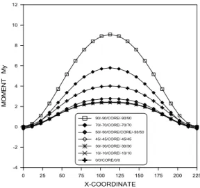
(9) Bending Analysis of Anisotropic Sandwich Plates with Multi-layered Laminated Composite faces. 40000. 3.00. 90/90/90/0/CORE/0/-90/-90/-90 70/70/70/-20/CORE/20/-70/-70/-70. 35000. 2.50. 45/45/45/-45/CORE/45/-45/-45/-45 30/30/30/-60/CORE/60/-30/-30/-30. 30000. 0/0/0/-90/CORE/90/0/0/0. 2.00. MOMENT (Mxy). MOMENT Mx. 25000. 1.50. 1.00. 0.50. 90/-90/CORE/-90/90 70/-70/CORE/-70/70. 20000 15000 10000 5000. 45/-45/CORE/-45/45. 0.00. 30/-30/CORE/-30/30. 0. 0/-0/CORE/-0/0. -0.50. -5000 -10000. -1.00 0. 25. 50. 75. 100. 125. 150. 175. 200. 0. 225. Fig. 9 Normalized moment (Mx) in y-direction with the variation of fiber angle Mx qz a . The [90/-90/core/-90/90] configuration yields the largest value of the normalized moment M y . plots are given in Fig.10. 12. 10. MOMENT My. 8. 6. 4. 2 90/-90/CORE/-90/90 70/-70/CORE/-70/70. 0. 50/-50/CORE/CORE/-50/50 45/-45/CORE/-45/45 30/-30/CORE/-30/30. -2. 10/-10/CORE/-10/10 0/0/CORE/0/0. -4 0. 25. 50. 75. 100. 125. 150. 175. 200. 225. X-COORDINATE. Fig. 10 Normalized moment(My) in x-direction with the variation of fiber angle My qz b . Fig. 11 shows the influence of antisymmetric angle-ply laminates with ply orientations CO RE Results are presented for the composites plate faces with four layer. The maximum value of the normalized moment M xy is seen to occur at [0/0/0/-90/core/90/0/0/0].. the. 25. 50. 75. 100. 125. 150. 175. 200. 225. X-COORDINATE. X-COORDINATE. lay-up. sequence,. Fig. 11. Normalized moment (Mxy) in x-direction with the variation of fiber angle Mxy qz a . 5. Conclusions The governing equations for bending analysis of composites sandwich plates with thick laminated faces based on zig-zag model are derived. In this study, results of the bending analysis under lateral uniform loads are shown for the composites sandwich plates with laminated faces. For the validation of this study, the present analysis was used for the general laminated plates. The current analysis result presented in this study shows higher than one by the first order shear deformation, but smaller than one by the higher order shear deformation theory in the laminated plates. As apply the present method to investigate the bending behavior of laminated plates, it is necessary to divide the laminated plate's thickness into three components, namely upper face, core, and lower face. The thickness of each component is arbitrary. The information presented in this study might be useful to the design of the composites sandwich plates with laminated faces. And since the present analysis considers the bending stiffness of the core and the transverse shear deformations of the laminated faces, it is expected that the analysis method is capable to analyze the general laminated plates considering shear deformations.. References Allen, H.G. (1969). "Analysis and design of structural. Vol. 3, No. 4, 2012. 25.
(10) Ji, Hyo-Seon. sandwich panels", Pergamon, Oxford. Ji, H. S., Song, W. C. and Ma, Z. John. (2010), " Design, test and field application of a GFRP corrugated-core sandwich bridge.", Eng. Struct., 32, pp. 2814-2824. Ji, H. S. and Chang, S. Y. (1998). “Analysis of composite sandwich plates with a local shear deformations.", J. of Korean Society of Steel Construction, 10(1), pp.557-570. Ji, H. S., Woo, Y. T. and Chang, S. Y. (1996). “Analysis of composite sandwich plates with thick core.”, J. of Korean Society Steel Construction, 8(2), pp.125-137. Libove, C. and Batdorf, S. B. (1948). "A general small deflection theory for flat sandwich plates.", NACA TN-1526. Mallikarjuna and Kant, T. (1993). " A critical review and some results of recently developed refined theories of fiber-reinforced laminated composites and sandwiches.", Compos. Struct., 23, pp.293-312. Pagano, N. J. (1972). "Exact solution for rectangular bidirectional composites and sandwich plates.", J. of Compos. Mater., 6, pp. 426-440. Park, D. Y., Noh, M. H. and Lee, S. Y. (2012). "EAS solid element for free vibration analysis of laminated composite and sandwich plate structures.", J of Korean Society for Advanced Compos Struct, 3(3), pp. 22-30. Reddy, J. N. (1984). "Energy and variational methods in applied mechanics", John Willy & Sons. Whintney, N. J. (1973). "Stress analysis of thick laminated composite and sandwich plates.", J. of Compos. Mater., 6, pp. 426-440.. 26. J. Korean Soc. Adv. Comp. Struc.
(11)
수치
![Fig. 3 Comparison of normalized central deflection with the side to thickness ratio (a/h) of a general laminated plates, [0/90]](https://thumb-ap.123doks.com/thumbv2/123dokinfo/5258018.630777/7.918.492.804.565.824/comparison-normalized-central-deflection-thickness-general-laminated-plates.webp)
![Table 3. Comparison of central deflection with the side to thickness ratio(a/h) of a sandwich plates [0/CORE/0], w z E t q z a theory a/h Ji et al.(1996) p r e s e n t 4 1 1 .7 3 4 9 7 .8 8 5 0 5 1 1 .7 3 4 9 7 .8](https://thumb-ap.123doks.com/thumbv2/123dokinfo/5258018.630777/8.918.97.434.140.656/table-comparison-central-deflection-thickness-sandwich-plates-theory.webp)
+2
관련 문서
44 글의 첫 번째 문장인 The most important thing in the Boat Race is harmony and teamwork.을 통해 Boat Race에서 가장 중요한 것은 조 화와 팀워크임을
The Dutch physicist Pieter Zeeman showed the spectral lines emitted by atoms in a magnetic field split into multiple energy levels... With no magnetic field to align them,
Modern Physics for Scientists and Engineers International Edition,
If both these adjustments are considered, the resulting approach is called a bootstrap-BC a -method (bias- corrected-accelerated). A description of this approach
③ A student who attended Korean course at KNU Korean Language Program and holds TOPIK Level 3 or a student who completed Korean course Level 4 at the KNU Korean Language
· 50% exemption from tuition fee Ⅱ for the student with a TOPIK score of level 3 or higher or completion of level 4 or higher class of the Korean language program at the
웹 표준을 지원하는 플랫폼에서 큰 수정없이 실행 가능함 패키징을 통해 다양한 기기를 위한 앱을 작성할 수 있음 네이티브 앱과
_____ culture appears to be attractive (도시의) to the
