INTRODUCTION
Stress distribution at the dental implant-cortical bone inter- face has been a major concern for researchers since the inception of dental implants. A lot research have been done in trying to reduce or redistribute the stress on the cortical bone and achieve stress pattern as close to natural tooth as possible.
Kirsch et al.1,2introduced the concept of resilient material between the implant fixture and superstructure. The concept of resilient material introduction derived by the fact, that the resilient mate- rial will be able to absorb and redistribute the stresses better, as compared to titanium abutment. A study by Achour et al.3 introduced an elastomeric material as stress breaker and con- cluded that the use of prosthetic material with lower stiffness was capable to diminish or to delay the loads transmitted to implants and to the bone.
However, studies by Holmes et al.4and McGlumphy et al.5 concluded that introduction of resilient material abutment does not result in significant reduction of cortical bone stress.
In another study, changing the shape of the resilient material
abutment produced only slight changes in the stress distribution in the cortical bone.6A study by Masaki et al.,7 in which they compared different resilient material abutment, con- cluded that there was no significant difference between the stress- es. Although a lot of finite element analysis also has been done using resilient material abutment materials, all these are sta- tic analysis.4,6,8 Since physiological loads in oral function such as mastication, time varying movements such as tapping and grinding should be simulated in a dynamic analysis.
In a dynamic study by Morton et al.,9in which they evalu- ated the bone strain, concluded that there is no substantial reduc- tion in measurable bone strain while using polyoxymethylene resilient material abutment as compared to titanium abut- ment. Recently, due to development of computer technologies, cyclic loading is simulated, by finite element method.
Therefore, in this experimental study, we compare the effect of different height polyoxymethylene resilient material abut- ment on the bone-implant interface, when compared with 3 mm titanium abutment using two dimensional dynamic finite ele- ment method.
Finite element study on the effect of abutment length and material on implant bone interface against dynamic loading
Manish Mishra*, BDS, Shogo Ozawa, DDS, PhD, Tatsuhiko Masuda, DDS, PhD, Fumi Yoshioka, DDS, PhD, Yoshinobu Tanaka, DDS, PhD
Department of Removal Prosthodontics, School of Dentistry, Aichi Gakuin University, Nagoya, Japan
PURPOSE. Finite element study on the effect of abutment length and material on implant bone interface against dynamic loading. MATERIALS AND METHODS. Two dimensional finite element models of cylinderical implant, abutments and bone made by titanium or polyoxymethylene were simulated with the aid of Marc/Mentat software. Each model represented bone, implant and titanium or polyoxymethylene abutment. Model 1: Implant with 3 mm titanium abutment, Model 2: Implant with 2 mm polyoxymethylene resilient material abutment, Model 3: Implant with 3 mm polyoxymethylene resilient material abutment and Model 4: Implant with 4 mm polyoxymethylene resilient material abutment. A vertical load of 11 N was applied with a frequency of 2 cycles/sec. The stress distribution pattern and displacement at the junction of cortical bone and implant was recorded. RESULTS. When Model 2, 3 and 4 are compared with Model 1, they showed narrowing of stress distribution pattern in the cortical bone as the height of the polyoxymethylene resilient material abutment increases. Model 2, 3 and 4 showed slightly less but similar displacement when compared to Model 1. CONCLUSION. Within the limitation of this study, we conclude that introduction of different height resilient material abutment with different heights i.e. 2 mm, 3 mm and 4 mm polyoxymethylene, does not bring about significant change in stress distribution pattern and displacement as compared to 3 mm Ti abutment. Clinically, with the application of resilient material abutment there is no significant change in stress distribution around implant-bone interface. [J Adv Prosthodont 2011;3:140-4]
KEY WORDS: Dental implant; Dynamic; Finite element analysis; Resilient material abutment; Polyoxymethylene; Bone-implant interface
Corresponding author: Manish Mishra
Dept. of Removable Prosthodontics, School of Dentistry, Aichi Gakuin University 2-11, Suemori-Dori, Chikusa-Ku, Nagoya City, 464-8651, Japan
Tel. 81 052 759 2152: e-mail, [email protected]
Received May 12, 2011 / Last Revison May 27, 2011 / Accepted June 2, 2011
ⓒ 2011 The Korean Academy of Prosthodontics
This is an Open Access article distributed under the terms of the Creative Commons Attribution Non-Commercial License (http://creativecommons.org/licenses/by- nc/3.0) which permits unrestricted non-commercial use, distribution, and reproduction in any medium, provided the original work is properly cited.
MATERIALS AND METHODS
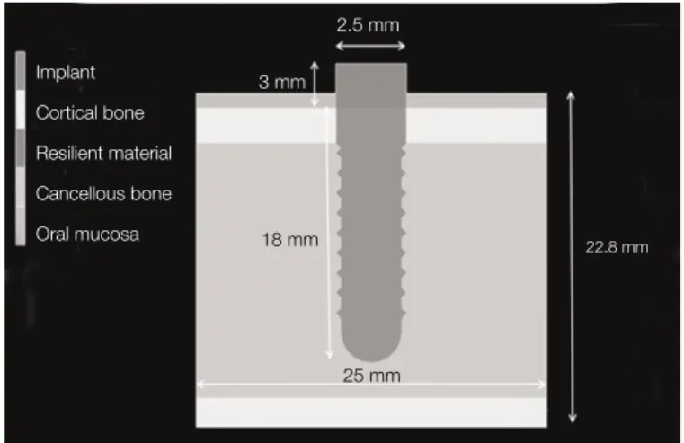
In this experimental study, cylindrical dental implant was select- ed for stress distribution pattern and displacement study. The cylindrical dental implant has polyoxymethylene resilient material abutment as an integral component of the dental implant system. This is a 2-dimensional, isotropic, homoge- neous and non-linear analysis. In this analysis, dental implant model was created and analyzed on MARC/Mentat (2005r3, MSC Software, USA). The dental implant has 18 mm height and 2.5 mm width. The dental implant consists of nine threads which are parallel, and triangular in shape. The dental implant
neck is 2.5 mm in length. The dental implant is placed inside the cortical bone with 1mm mucosa covering the cortical bone. ‘Model 1’has 3 mm of Titanium as abutment in the den- tal implant system while ‘Model 2, 3 and 4’have heights of 2 mm, 3 mm, and 4 mm of polyoxymethylene resilient mate- rial abutment in the dental implant system, shown in Fig. 1. The mandibular bone is shown as rectangular block. The mandibu- lar bone is 22.8 mm in height and 25 mm in width. The mandibular bone consists of 2.5 and 2.3 mm of cortical bone on the superior and the inferior surface respectively. The cancellous bone lies between the layers of cortical bone and is 18 mm in height. Model 1 dental implant and bone consist of 2015 nodes and 2052 elements, while nodes and elements in Model 2, 3 and 4 dental implants and bone are shown in Fig.
2. All elements are tetrahedral in shape as shown in Fig. 3.
The nodes on the neck region of the dental implant and side of the mandibular bone are fixed in X direction while the nodes on the lower surface of the mandibular bone are fixed in X and Y direction as shown in Fig. 3. The implant and resilient material make up first contact body while the cortical and can- cellous bone along with oral mucosa make up the second con- tact body as shown in Fig. 4. The friction coefficient for the dental implant and mandibular bone is 0.3. The mechanical prop- erties of the bone and implant models are shown in Table 1.
The total load at the implant abutment is 11 N, 1 N at each node. The load application is cyclic in nature. The total
Fig. 1. Implant, abutment and bone.
Fig. 2. Nodes and Elements in different models.
Implant Cortical bone Resilient material Cancellous bone Oral mucosa
3 mm
2.5 mm
22.8 mm 18 mm
25 mm
Resilient Material-2 mm Nodes : 2011 Elements : 2016
Resilient Material-3 mm Nodes : 2051 Elements : 2052
Resilient Material-4 mm Nodes : 2121 Elements : 2116
Fig. 3. Boundary conditions.
Table 1. Material properties of constituents materials
Material Young’s Modulus (MPa) Poisson’s ratio
Titanium107,000 0.34
Cortical Bone 13,700 0.30
Cancellous Bone 690 0.30
Oral Mucosa 3.43 0.45
Polyoxymethylene 3450 0.35
Load Fixed in X direction Fixed in X-Y direction
cycles are 7200 in 3600 sec with frequency 2 cycles/sec.
The investigating area for stress distribution pattern and dis- placement is the bone-implant interface, at the border between the dental implant, resilient material, cortical bone and oral mucosa as shown in Fig. 5.
We compare the effect of introducing different height poly- oxymethylene resilient material abutment on the bone-implant interface with 3mm Titanium abutment. We compare the stress distribution pattern and displacement of Model 2, 3, and 4 with Model 1 in two-dimensional dynamic finite element analysis.
RESULTS
The finite element analysis executed by MARC/Mentat gives us the Von Mises stress pattern of the Model 1 and Model 2, 3 and 4. Von Mises stress was considered as it gives us unique value for all the six stress components.
The stress distribution pattern of Model 1 and Model 2 is com- pared in Fig. 6. The bone-implant interface shows stress dis- tribution pattern almost the same. There is slight reduction in stress magnitude as shown in Fig. 9.
Fig. 7 shows the stress pattern of Model 1 and Model 3. The stress distribution pattern similar is to Model 2. However, in this case the stress distribution pattern is narrower than Model 2 and stresses are slightly lower in magnitude in bone-implant interface as seen in Fig. 9.
The stress distribution of Model 1 and Model 4 is seen in Fig.
8. The stress distribution pattern is similar to Model 2 at the bone-implant interface. However, the stress distribution is slight- ly narrower than Model 3 and stresses are slightly lower in mag- nitude as seen in Fig. 9.
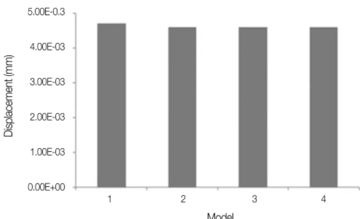
When a comparison was made between displacement at the bone-implant interface we conclude that the displace- ment pattern are almost equal as shown in Fig. 10.
Fig. 4. Contact conditions. Fig. 5. Stress and displacement measuring point at the junction of abutment, implant, cortical bone and oral mucosa.
Fig. 6. Stress profile of Model 1 and Model 2.
Fig. 7. Stress profile of Model 1 and Model 3.
Fig. 8. Stress profile of Model 1 and Model 4.
Implant, Resilient material Bone tissue, Oral mucosa
Stress pattern
Model 1 Model 4 Stress pattern
Model 1 Model 3 Stress pattern
Model 1 Model 2
DISCUSSION
The role of stress absorbing elements in implant system has been analyzed in various studies.10 The resilient material abutment can help in damping the height of peak stresses in dynamic loading and also in stress absorbing/ stress distributing the forces experienced by the dental implant system. The latter function depends upon the implant system and materi- al properties.6This experimental study uses finite element method to compare the stress distribution pattern and displacement on the bone-implant interface with the introduction of different lengths polyoxymethylene resilient material abutment, and 3 mm titanium abutment.
This study shows that polyoxymethylene resilient material abutment results in slight change in the stress magnitude in the bone-implant interface, which is insignificant. This may be due to polyoxymethylene resilient material abutment having Young’s modulus (3,450 MPa) much lower than titanium (107,000 MPa). The reduction in Young’s modulus leads to slight decrease in stress as compared to Model 1.
Our study is in accordance with a study by Geng et al.11, in which they concluded that there is no significant difference in stress when resilient material abutment was modeled in poly- oxymethylene rather than titanium.
Changing the height of polyoxymethylene resilient materi- al abutment leads to slight change in distribution of stress pat- tern, but it is also insignificant. This change can be attributed to the increased height of the polyoxymethylene resilient material abutment and lower Young’s modulus of the poly- oxymethylene resilient material abutment when compared to 3 mm titanium abutment.
The displacement pattern at the bone-implant interface shows, introduction of polyoxymethylene resilient material abut- ment leads to slight change in the displacement magnitude, which is inappreciable. Also changing the height of the poly-
oxymethylene resilient material abutment leads to inappreciable change in displacement magnitude when compared with 3 mm titanium abutment.
In this experimental study, we have introduced dynamic load- ing in finite element analysis. In oral cavity most of loading is dynamic in nature so evaluating the loading conditions in sta- tic loading leads to simplification of the complex biome- chanical process taking place inside the oral cavity.
With the introduction of dynamic loading there is no significant change in the magnitude of the stress or the displacement. This may be attributed to the fact that there are no cumulative stress- es transferred to the cortical bone which may show increase in stress magnitude with time. Hence, the magnitude of the stress and displacement remains the same in dynamic loading.
The introduction of lower Young’s modulus polyoxymeth- ylene resilient material abutment does not lead to signifi- cant change in the stress and displacement pattern as compared to titanium abutment in dynamic loading. Hence introduction of lower Young’s modulus does not change the parameters sig- nificantly, in dynamic loading in relation of stress and dis- placement distribution.
There are limitations in this study as the bone is assumed to be homogeneous, isotropic, while the bone is non-homogeneous and anisotropic. The load applied is 11 N, as we were inves- tigating the change in the stress distribution pattern and dis- placement, which can easily be accomplished by applying 1 N load for all the 11 nodes on the top of the abutment. The total time evaluated in this study was 3600 seconds, in order to ease computational load, as all non-linear finite element analysis takes more time than static finite element analysis to solve the mathematical model. The above mentioned applied load and conditions indicate that the stress results are not absolute but relative in nature. This is a qualitative analysis and not a quantitative analysis with 2 dimensional finite element method.
Fig. 9. Stress value at the measuring point. Fig. 10. Displacement value at the measuring point.
1.00E+00 9.00E-01 8.00E-01 7.00E-01 6.00E-01 5.00E-01 4.00E-01 3.00E-01 2.00E-01 1.00E-01 0.00E+00
Stress (MPa)
5.00E-0.3
4.00E-03
3.00E-03
2.00E-03
1.00E-03
0.00E+00
Displacement (mm)
1 2 3 4 Model
1 2 3 4 Model
The marginal bone loss is due to one or combination of the following factors i.e. occlusal overload, microgap, and impact crest module.12In this study we changed the height and young modulus of the abutment material as one of variations of occlusal overload in order to study its effects on marginal bone loss.
CONCLUSION
Within the limitation of this study we can conclude that chang- ing the Young’s modulus and height of the resilient material abutment does not significantly change the stress and dis- placement pattern at the bone-implant interface as compared to 3 mm titanium abutment. This leads us to conclude that the dental implant and bone interface is not influenced by the addi- tion of lower Young’s modulus resilient material abutment.
Clinically, the introduction of polyoxymethylene resilient abut- ment material does not cause any significant changes in stress and displacement pattern at bone-implant interface hence its introduction does not play any role in marginal bone loss (saucerization).
REFERENCES
1. Kirsch A, Mentag PJ. The IMZ endosseous two phase im- plant system: a complete oral rehabilitation treatment concept.
J Oral Implantol 1986;12:576-89.
2. Babbush CA, Kirsch A, Mentag PJ, Hill B. Intramobile cylin- der (IMZ) two-stage osteointegrated implant system with the in-
tramobile element (IME): part I. Its ratinale and procedure for use. Int J Oral Maxillofac Implants 1987;2:203-16.
3. Achour T, Merdji A, Bachir BB, Serier B, Djebbar N. Stress dis- tribution in dental implant with elastomeric stress barrier.
Mater Design 2011;32:282-90.
4. Holmes DC, Grigsby WR, Goel VK, Keller JC. Comparison of stress transmission in the IMZ implant system with poly- oxymethylene or titanium intramobile element: a finite ele- ment stress analysis. Int J Oral Maxillofac Implants 1992;7:
450-8.
5. McGlumphy EA, Campagni WV, Peterson LJ. A comparison of the stress transfer characteristics of a dental implant with a rigid or a resilient internal element. J Prosthet Dent 1989;62:586- 93.
6. van Rossen IP, Braak LH, de Putter C, de Groot K. Stress- absorbing elements in dental implants. J Prosthet Dent 1990;64:
198-205.
7. Sato M, Kuboki T, Itasaka M, Kondo Y, Yamashita A. Stress- transfer characteristics of stress-absorbing elements in the IMZ implant system: Part 1. Stress around a freestanding single implant under static loading conditions. J Jpn Prosthodont Soc 1992;36:1102-10.
8. Haganman CR, Holmes DC, Aquilino SA, Diaz-Arnold AM, Stanford CM. Deflection and stress distribution in three different IMZ abutment designs. J Prosthodont 1997;6:110-21.
9. Morton D, Stanford CM, Aquilino SA. Evaluation of resilient abutment components on measured strain using dynamic load- ing conditions. J Prosthet Dent 1998;80:46-51.
10. Skalak R. Biomechanical considerations in osseointegrated prostheses. J Prosthet Dent 1983;49:843-8.
11. Geng JP, Tan KB, Liu GR. Application of finite element analy- sis in implant dentistry: a review of the literature. J Prosthet Dent 2001;85:585-98.
12. Oh TJ, Yoon J, Misch CE, Wang HL. The causes of early im- plant bone loss: myth or science? J Periodontol 2002;73:322-33.