INTRODUCTION
The major contributing factor leading to late failure of implant-supported restorations seems to be a lack of understanding of biomechanical concepts
1). Bioenginee- ring studies have been useful for determining the opti- mal prosthesis design and understanding the response of biologic tissues to relevant forces
2-4). Biomechanical fac- tors play an important role in the long-term survival of dental implants. The selection of implant position is criti- cal for the longevity and stability of an implanted pros- thesis
5).
Two different kinds of implant placement methods are used in the field of recent oral implantology: submerged (two-stage surgical procedure) and non-submerged (one- stage surgery) type implants
6). Multicenter studies have reported satisfactory success rates for both protocols and a similar loss of crestal peri-implant bone after occlusal loading (0.5 to 1.5 mm). The major problem with the sub- merged approach is the countersinking process needed to submerge the implant. In order to accommodate the implant head and cover screw, the crestal bone must be widened approximately. When the labio-lingual width of the alveolar bone is less than 6 mm, the bone is too thin for implantation of standard diametered fixtures and the bone around the implant is eventually absorbed.
Consequently, the bone loss would be less than 0.5 mm.
Davarpanah and coworkers
7)first reported the concept of
* Corresponding author Su-Gwan Kim D.D.S., Ph.D
Dept. of OMFS, College of Dentistry, Chosun University, 421, SeoSeogDong, DongGu, GwangJu City, 501-825, Korea
Finite Element Stress Analysis according to Apical-coronal Implant Position
Tae-Ho Kang, Su-Gwan Kim
Department of Oral and Maxillofacial Surgery, Oral Biology Research Institute, College of Dentistry, Chosun University
Purpose:The purpose of this study was to evaluate the influence of apical-coronal implant position on the stress distribution after occlusal and oblique loading.
Materials and Methods: The cortical and cancellous bone was assumed to be isotropic, homogeneous, and linearly elastic.
The implant was apposed to cortical bone in the crestal region and to cancellous bone for the remainder of the implant-bone interface. The cancellous core was surrounded by 2-mm-thick cortical bone. An axial load of 200 N was assumed and a 200-N oblique load was applied at a buccal inclination of 30 degrees to the center of the pontic and buccal cusps. The 3-D geometry modeled in Iron CAD was interfaced with ANSYS.
Results: When only the stress in the bone was compared, the minimal principal stress at load Points A and B, with a axial load applied at 90 degrees or an oblique load applied at 30 degrees, for model 5. The von Mises stress in the screw of model 5 was minimal at Points A and B, for 90- and 30-degree loads. When the von Mises stress of the abutment screw was compared at Points A and B, and a 30-degree oblique load, the maximum principal stress was seen with model 2, while the minimum princi- pal stress was with model 5. In the case of implant, the model that received maximum von Mises stress was model 1 with the load Point A and Point B, axial load applied in 90-degree, and oblique load applied in 30-degree.
Discussion and Conclusions:These results suggests that implantation should be done at the supracrestal level only when necessary, since it results in higher stress than when implantation is done at or below the alveolar bone level. Within the limited this study, we recommend the use of supracrestal apical-coronal positioning in the case of clinical indications.
Key words
Finite element stress analysis, Apical-coronal implant position Abstract
tion using supracrestal placement.
Even when the labio-lingual width of alveolar bone is narrow, countersinking is unnecessary with supracrestal placement, and the biological width is maintained, reducing bone loss.
Recently, supracrestal apical-coronal positioning of the implant collar has been proposed for posterior sectors using submerged implants
7). The advantages of supracre- stal apical-coronal positioning are as follows: little or no countersinking is needed; there is no need for underseat- ing when connecting the abutment; soft tissue manage- ment is simple; the surgical procedure and suturing are simple; longer implants can be used; the clinical crown- implant ratio and implant anchorage surface increase;
the second surgical phase and prosthetic restoration are facilitated; the amount of peri-implant crestal bone loss is reduced or limited; and there is optimal initial stability
7).
Three-dimensional finite element stress analysis (FEA) is a technique that is used to solve engineering problems.
It can be used in numeric simulations to determine stress and displacement, via its ability to model geometrically complex structures. The method has been extensively used to study the biomechanics of dental implants and has many advantages over other methods
8).
A few FEA studies have built a 3-D finite element mod- el database of the mandible
9-11). However, as far as I know, no FEA analysis has tried to study the stress dis- tribution according to apical-coronal implant position.
The purpose of this study was to evaluate the influence
of apical-coronal implant position on the stress distribu- tion after occlusal and oblique loading.
MATERIALS AND METHODS
Three-dimensional (3-D) geometry formation
A mandible taken from a fresh cadaver was digitized using a surface scanner. Modeling was done using 3-D computer-assisted design (IronCAD ver. 6.0, Atlanta, GA). The model consisted of a 30-mm piece of bone, which included 15 mm on each side of the tooth center.
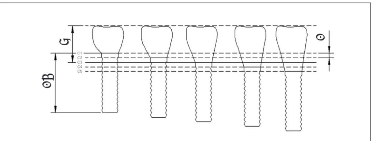
In addition, the mandibular bone model was divided into cortical and cancellous bone for a more detailed analysis. Computed tomography (CT) images of actual mandibular bone were used to make more accurate mod- el. The five lines in Fig. 1 were designated as lines 1 to 5 from top to bottom, respectively. The 3-D geometry of the full body for the external implant/abutment connec- tion is shown in Fig. 2.
Construction of 3-D finite element analysis model The cortical and cancellous bone was assumed to be isotropic, homogeneous, and linearly elastic. The implant was apposed to cortical bone in the crestal region and to cancellous bone for the remainder of the implant-bone interface. The cancellous core was surrounded by 2-mm- thick cortical bone. The cancellous bone was classified as dense because of the anatomical structure of the mandible.
Fig. 1.Apical-coronal implant position. C1 = 2 mm supracrestal implant position; C2 = 1 mm supracrestal implant position; C3 = crest of cortical bone; C4 = 1 mm subcrestal implant position; C5 = 2 mm subcre- stal implant position.
8 1
13
To simulate complete osseointegration, the implants were rigidly anchored along the entire interface in the bone model (Fig. 3). Young’s modulus for cortical and cancellous bone was assumed to be 13,700 and 1,370 MPa, respectively. Poisson’s ratio was 0.3 for both (Table 1).
The 3-D geometry modeled in Iron CAD was interfaced with ANSYS ver. 7.0 (ANSYS Inc., Canonsburg, PA, USA) to generate a grid. This process considered consis- tent, so that the number of elements and nodes would be similar for each model. Consequently, the element used was a tetrahedral element with eight nodes (Table 2).
Implants
AVANA dental implants (Osstem, Busan, Korea), external fixture, were designed at five different bone
depths for each implant/abutment connection. Self-tap- ping, screw-type implants 11.5 mm long and 4 mm in diameter was selected as an external type fixture (Fig. 3).
Loads and boundary conditions (Fig. 4)
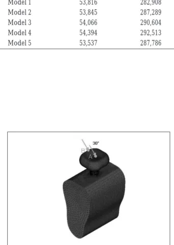
An axial load of 200 N was assumed (Fig. 5); this is referred to as the 90-degree axial load. A 200-N oblique load was applied at a buccal inclination of 30 degrees to the center of the pontic and buccal cusps (Fig. 6). Loads were applied at Points A and B. Both ends of the bone were bounded (x-, y-, z-dimensions).
Solution
Solutions were obtained using ANSYS. Both overall and each component (bone, screw, abutment screw, implant) stress were analyzed and expressed in von
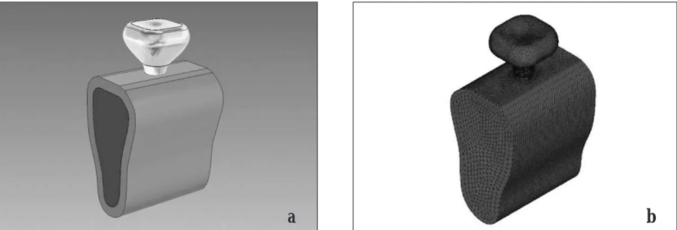
Fig. 2.3-D geometry of full body (a) and 3-D finite element model (b).
Table 1.Material Properties
Young’s Modulus Possion’s
(MPa) Ratio
Compact bone 13,700 0.3
Cancellous bone 1,370 0.3
Implant 115,000 0.35
Titanium screw 115,000 0.35
Gold crown 96,600 0.35
a b
Mises stress (equivalent stress). The stress patterns were displayed as contour lines with different colors connect- ing regions of equal stress within defined limits.
RESULTS
To evaluate the stress distribution, the magnitude of the stress concentration was presented as the minimum (compressive stress) and maximum (tensile stress) princi- pal stress.
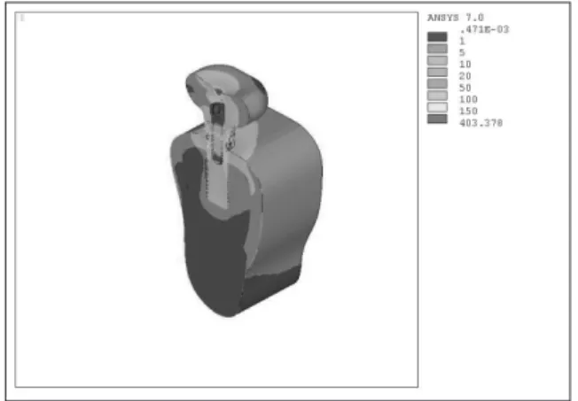
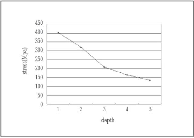
Both overall and each component (bone, screw, abut- ment screw, implant) stress were expressed from Fig. 7 to Fig. 11. When only the stress in the bone was com- pared, the minimal principal stress at load Points A and B, with a axial load applied at 90 degrees or an oblique load applied at 30 degrees, for model 5 (Figs 12 and 13).
The von Mises stress in the screw of model 5 was mini- mal at Points A and B, for 90- and 30-degree loads (Figs 14 and 15). When the von Mises stress of the abutment screw was compared at Points A and B, and a 30-degree oblique load, the maximum principal stress was seen with model 2, while the minimum principal stress was with model 5 (Figs 16 and 17). In the case of implant, the model that received maximum von Mises stress was model 1 with the load Point A and Point B, axial load applied in 90-degree, and oblique load applied in 30- degree (Fig. 18).
Overall, the maximum von Mises stress in the models increased in the order of 5<4<3<2<1. Moreover, for an applied load at the same point, the stress was greater with an oblique load than with a axial load.
Fig. 4.Points subjected to loading.
Fig. 5.Load when a 90-degree axial force was applied. Fig. 6.Load when a 30-degree oblique force was applied.
Table 2. Numbers of Elements and Nodes in the Mandible Model
Node Element
Model 1 53,816 282,908
Model 2 53,845 287,289
Model 3 54,066 290,604
Model 4 54,394 292,513
Model 5 53,537 287,786
Fig. 7.Equivalent stress in overall form (model 1, 30- degree, Point A).
Fig. 8.Equivalent stress in implant (model 1, 30-degree, Point A).
Fig. 9.Equivalent stress on bone surface (model 1, 30- degree, Point A).
Fig. 10.Each component (implant, abutment, and crown) stress.
Fig. 11.Equivalent stress on overall surface (model 1, 30-degree, Point A).
Fig. 12.Comparison of the von Mises stress according to apical-coronal implant position (loading site=A, load=30-degree).
1 2 3 4 5
depth 140
120 100 80 60 40 20 0
stress(Mpa)
Fig. 13.Comparison of the stress according to apical- coronal implant position (loading site=A, load=90- degree).
Fig. 14.Stress comparison for an external screw (load- ing site=A, load=30-degree).
Fig. 15.Stress comparison for an external screw (load- ing site=B, load=90-degree).
Fig. 16.Stress differences in the abutment screw (load- ing site=A, load=30-degree).
Fig. 17.Stress differences in the abutment screw (load- ing site=B, load=30-degree).
Fig. 18.Von Mises stress in the implant (loading site=A, load=30-degree).
1 2 3 4 5
depth
1 2 3 4 5
depth
1 2 3 4 5
depth
1 2 3 4 5
depth
1 2 3 4 5
depth
1 2 3 4 5
depth 35
30 25 20 15 10 5 0
stress(Mpa)
450 400 350 300 250 200 150 100 50 0
stress(Mpa)
350 300 250 200 150 100 50 0
stress(Mpa)
90 80 70 60 50 40 30 20 10 0
stress(Mpa)
140 120 100 80 60 40 20 0
stress(Mpa)
250
200
150
100
50
0
stress(Mpa)
DISCUSSION
Finite element analysis (FEA) is a precise method for evaluating dental implant systems. It has been used extensively to predict the biomechanical performance of various dental implant designs and the effect of clinical factors on implant success
12,13). By understanding the basic theory, method, application, and limitations of FEA in implant dentistry, the clinician will be better equipped to interpret the results of FEA studies and extrapolate those results to clinical situations
13).
However, FEA has inherent limitations. The stress val- ues that actually cause biologic changes in bone, such as resorption and remodeling, are not known. In addition, the stress values calculated using FEA are not necessarily identical to actual values
14).
The von Mises stress is defined as the stress at which the deformation of ductile materials, such as metallic implants, begins. Since failure occurs when the von Mises stress exceeds the yield strength of an implant, von Mises stress criteria are important for interpreting the stresses that occur within the implant
1). The principal stress can be used to distinguish tensile and compressive stress.
In order to improve osseointegration, recent studies have focused on implant position, shape, and surface characteristics
2-4,15). Stress around implants may lead to bone resorption and implant loss
16). Therefore, determin- ing the stress distribution and intensity is important for understanding the process that leads to the loss of inte- gration.
Insufficient bone volume and increased prosthetic space may be encountered in the placement of supracre- stal implants (3 to 4 mm); consequently, the process can be combined with a guided tissue regeneration proce- dure in order to increase the alveolar ridge height
17).
Supracrestal apical-coronal positioning of the collar improves the clinical crown-implant ratio and the implant anchorage surface. In posterior sectors, an implant that is 1.5 mm longer may be used, and this markedly increases anchorage. The combination of a rough surface and a supracrestal apical-coronal position increases implant anchorage considerably
7).
The disadvantages of supracrestal apical-coronal posi- tioning are: osseointegration could fail due to overload;
failure could result when primary stability is insufficient;
there is the possibility of metal exposure in the esthetic zone (anterior area); and implant micromovement can occur
7).
Contraindications for this surgical technique are: when there is a minimum difference in the crestal bone level between the implant and adjacent teeth; when the inter- maxillary distance is less than 6 mm; or when the mucosa is very thin
7). Supracrestal apical-coronal posi- tioning should be used selectively when bone quality is good, primary stability is sufficient, and the intermaxil- lary distance is sufficient.
Mericske-Stern and coworkers
18)explored the occlusal force in a group of partially edentulous patients restored using ITI implants supporting a fixed partial prosthesis.
They found that the range of occlusal force on the second premolar and molar teeth was 210-400 N and 130-395 N, respectively. In this study, a static load of 200 N was applied at a buccal inclination of 30 degrees and 90 degree to the buccal cusps.
Since the number of clinical cases needing supracrestal apical-coronal positioning is increasing, this study exam- ined the utility of FEA. In this study, the maximum von Mises stress occurred with model 1, especially at a 30- degree oblique load. Moreover, the minimum von Mises stress occurred with model 5. For an abutment screw, the maximum principal stress occurred with model 2, while the minimum principal stress was with model 5.
Overall, the maximum principal stress increased as the model decreased from 5 to 1 and the minimum principal stress decreased as the model increased from 1 to 5.
Our finite element analysis suggests that implantation
should be done at the supracrestal level only when nec-
essary, since it results in higher stress than when implan-
tation is done at or below the alveolar bone level. Within
the limited this study, we recommend the use of
supracrestal apical-coronal positioning in the case of clin-
ical indications. Nevertheless, an implant that is posi-
tioned too deep is not good for the gingiva in the long
term because of difficulties in tissue maintenance and tis-
sue management. Crestal bone loss is the most common
cause of implant failure when osseointegration has been
achieved
19). Therefore, further animal and clinical studies
are needed. Our analysis considered implantations of the
same length; additional analysis is needed for cases in
which the length of implant increases as the clinical
crown becomes shorter and vice versa.
REFERENCES
1. Akca K, Iplikcioglu H: Finite element stress analysis of the influence of staggered versus straight placement of dental implants. Int J Oral Maxillofac Implants 2001;16:722-730.
2. Cooper LF, Masuda T, Yliheikkila PK, Felton DA:
Generalizations regarding the process and phenomenon of osseointegration. Part II. In vitro studies. Int J Oral Maxillofac Implants 1998;13:163-174.
3. Masuda T, Yliheikkila PK, Felton DA, Cooper LF:
Generalizations regarding the process and phenomenon of osseointegration. Part I. In vivo studies. Int J Oral Maxillofac Implants 1998;13:17-29.
4. Quirynen M, Naert I, van Steenberghe D: Fixture design and overload influence marginal bone loss and fixture suc- cess in the Branemark system. Clin Oral Implants Res 1992;3:104-111.
5. Ciftci Y, Canay S: The effect of veneering materials on stress distribution in implant-supported fixed prosthetic restorations. Int J Oral Maxillofac Implants 2000;15:571-582.
6. Boioli LT, Penaud J, Miller N: A meta-analytic, quantitative assessment of osseointegration establishment and evolu- tion of submerged and non-submerged endosseous titani- um oral implants. Clin Oral Implants Res 2001;12:579-588.
7. Davarpanah M, Martinez H, Tecucianu JF: Apical-coronal implant position: recent surgical proposals. Technical note.
Int J Oral Maxillofac Implants 2000;15:865-872.
8. Williams KR, Watson CJ, Murphy WM, Scott J, Gregory M, Sinobad D: Finite element analysis of fixed prostheses at- tached to osseointegrated implants. Quintessence Int 1990;21:563-570.
9. Kregzde M: A method of selecting the best implant pros- thesis design option using three-dimensional finite element analysis. Int J Oral Maxillofac Implants 1993;8:662-673.
10. Meijer HJ, Starmans FJ, Steen WH, Bosman F: A three-di- mensional, finite-element analysis of bone around dental implants in an edentulous human mandible. Arch Oral Biol 1993;38:491-496.
11. van Zyl PP, Grundling NL, Jooste CH, Terblanche E: Three- dimensional finite element model of a human mandible in- corporating six osseointegrated implants for stress analysis of mandibular cantilever prostheses. Int J Oral Maxillofac Implants 1995;10:51-57.
12. Holmgren EP, Seckinger RJ, Kilgren LM, Mante F:
Evaluating parameters of osseointegrated dental implants using finite element analysis--a two-dimensional compara- tive study examining the effects of implant diameter, im- plant shape, and load direction. J Oral Implantol 1998;
24:80-88.
13. Geng JP, Tan KB, Liu GR: Application of finite element analysis in implant dentistry: a review of the literature. J Prosthet Dent 2001;85:585-598.
14. Akca K, Iplikcioglu H: Evaluation of the effect of the resid- ual bone angulation on implant-supported fixed prosthesis in mandibular posterior edentulism. Part II: 3-D finite ele- ment stress analysis. Implant Dent 2001;10:238-245.
15. De Leonardis D, Garg AK, Pecora GE: Osseointegration of rough acid-etched titanium implants: 5-year follow-up of 100 minimatic implants. Int J Oral Maxillofac Implants 1999;14:384-391.
16. Lai H, Zhang F, Zhang B, Yang C, Xue M: Influence of per- centage of osseointegration on stress distribution around dental implants. Chin J Dent Res 1998;1:7-11.
17. Martinez H, Davarpanah M, Missika. Implant treatment for the posterior regions: classification. In: Davarpanah M, Martinez H, Kebir M, Tecucianu JF (eds). Clinical Manual of Implant Dentistry. Chicago: Quintessence, 2003:156.
18. Mericske-Stern R, Assal P, Mericske E, Burgin W: Occlusal force and oral tactile sensibility measured in partially eden- tulous patients with ITI implants. Int J Oral Maxillofac Implants 1995;10:345-353.
19. O’Mahony AM, Williams JL, Spencer P: Anisotropic elas- ticity of cortical and cancellous bone in the posterior mandible increases peri-implant stress and strain under oblique loading. Clin Oral Implants Res 2001;12:648-657.