Effects of cementless fixation of implant prosthesis: A finite element study
Hyeonjong Lee1a, Soyeon Park2a, Kung-Rock Kwon3, gunwoo Noh2*
1Department of Prosthodontics, School of Dentistry, Pusan National University, Yangsan, Republic of Korea
2School of Mechanical Engineering, Kyungpook National University, Daegu, Republic of Korea
3Department of Prosthodontics, School of Dentistry, Kyung Hee University, Seoul, Republic of Korea
PURPOSE. A novel retentive type of implant prosthesis that does not require the use of cement or screw holes has been introduced; however, there are few reports examining the biomechanical aspects of this novel implant.
This study aimed to evaluate the biomechanical features of cementless fixation (CLF) implant prostheses.
MATERIALS AND METHODS. The test groups of three variations of CLF implant prostheses and a control group of conventional cement-retained (CR) prosthesis were designed three-dimensionally for finite element analysis.
The test groups were divided according to the abutment shape and the relining strategy on the inner surface of the implant crown as follows; resin-air hole-full (RAF), resin-air hole (RA), and resin-no air hole (RNA). The von Mises stress and principal stress were used to evaluate the stress values and distributions of the implant components. Contact open values were calculated to analyze the gap formation of the contact surfaces at the abutment-resin and abutment-implant interfaces. The micro-strain values were evaluated for the surrounding bone. RESULTS. Values reflecting the maximum stress on the abutment were as follows (in MPa): RAF, 25.6; RA, 23.4; RNA, 20.0; and CR, 15.8. The value of gap formation was measured from 0.88 to 1.19 μm at the abutment- resin interface and 24.4 to 24.7 μm at the abutment-implant interface. The strain distribution was similar in all cases. CONCLUSION. CLF had no disadvantages in terms of the biomechanical features compared with conventional CR implant prosthesis and could be successfully applied for implant prosthesis. [J Adv Prosthodont 2019;11:341-9]
KEYWORDS: Finite element analysis; Implant prosthesis; Cementless fixation
Corresponding author:
Gunwoo Noh
School of Mechanical Engineering, Kyungpook National University,
#319 Bld. 6 College of Engineering, 1370 Sankyuk-dong, Buk-gu, Daegu 41566, Republic of Korea
Tel. +82539505575: e-mail, [email protected]
Received August 1, 2019 / Last Revision November 1, 2019 / Accepted December 10, 2019
© 2019 The Korean Academy of Prosthodontics
This is an Open Access article distributed under the terms of the Creative Commons Attribution Non-Commercial License (http://creativecommons.
org/licenses/by-nc/4.0) which permits unrestricted non-commercial use, distribution, and reproduction in any medium, provided the original work is properly cited.
INTRODUCTION
Implant-supported fixed dental prosthesis (FDP) is a well- documented treatment option for partially or completely
edentulous patients. FDP enhances the masticatory function, as well as esthetics, and has high success and survival rates.1,2 Implants are conventionally retained using screws or cement, and FDP has advantages and disadvantages associated with cement remnants, screw hole creation, and retrievability.3-9
Screw retention avoids the problem of cement remnants and allows good retrievability; however, it requires the cre- ation of a screw hole on the occlusal surface. Although the hole can be filled with composite resin, microleakage can occur if the occlusal contact point is on the filled resin.10 The hole occupies a portion of the occlusal table and the occupied proportion is higher when the occlusal table area is small.11 Additionally, positioning of the screw on the labial surface of incisors leads to esthetic problems.12,13
Cement retention is associated with occlusal integrity;
however, it is not easy to ensure that the cement remnants have been completely removed from the subgingival area.3,11 The problems with cement remnants and retrievability are the main drawbacks of cement-retained (CR) implant pros- theses. Cement remnants could accumulate in the subgingi-
a These authors contributed equally as first authors.
This work was partly supported by National Research Foundation of Korea (NRF) funded by the Ministry of Education of Korea (2018R1D1A1B07049789) and Korea Institute of Advancement of Technology(KIAT) funded by the Korea Government(MOTIE) (P002007).
val area even after a thorough removal process14,15 and lead to peri-implantitis.3 CR implant prostheses were also report- ed to demonstrate relatively poor retrievability.16
A novel retentive type of implant prosthesis that does not require the use of cement or screw holes has been intro- duced. Cementless fixation (CLF) provides a precise fit between the implant crown and the abutment because the inner surface of the implant crown is relined using flowable composite resin during the fabrication process. CLF requires a sunken structure on the occlusal surface of the abutment called the air hole, which is created to evenly distribute stresses over the occlusal surface. However, there are few reports examining the biomechanical aspects of the CLF implant crown. The optimal design for decreasing the stress distribution on the CLF implant crown has not yet been studied. This study aimed to evaluate the biomechanical fea- tures of the different designs of CLF implant crowns through finite element (FE) analysis, including stress analysis, gap formation on the faced interfaces, and strain analysis of the surrounding peri-implant bone.
MATERIALS AND METHODS
Three-dimensional (3D) models were prepared for analysis and the stability of four implant systems were compared and analyzed through FE analysis including preloading generated by the screw-tightening process and mastication simulation.
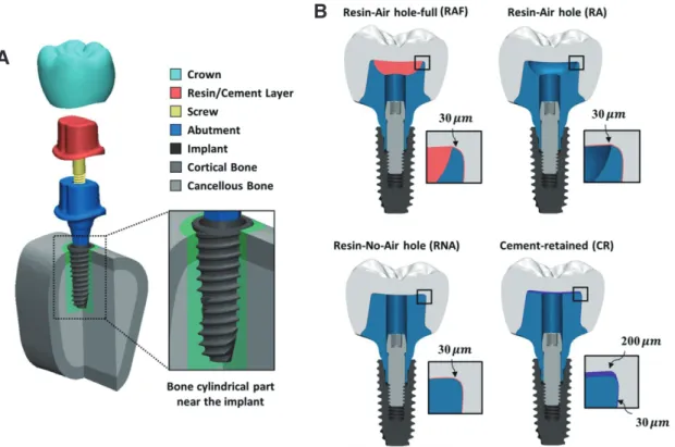
Fig. 1 shows FE models and the structure of the implant complex of three cases that used CLF implant prostheses and one case that used a cement-retained (CR) implant. For each implant system, the model consisted of the crown, res- in/cement layer, abutment, screw, and the implant inserted in the bone (Fig. 1A). Three CLF implant prosthesis test groups were classified according to the shape of the abut- ment: the resin-air hole-full (RAF) group had abutments with air hole filled with composite resin, the resin-air hole (RA) group had abutments with air holes without resin fill- ings, and the resin-no-air hole (RNA) group had abutments with no air holes. For CLF implant systems, the air groups (RA, RAF) and no air group (RNA) depended on the abut- ment geometries. The sunken structure on the occlusal sur- face of the abutment was designed to reveal the effect of stress distribution on the implant and abutment. CR implant prosthesis was used as the control group. Each implant sys- tem used an internal hex implant with a diameter of 4.0 mm, implant length of 10 mm, and a total length of 20 mm. The design of the implant models was provided by the manufac- turer (Osstem Implant Co. Ltd., Seoul, South Korea).
The modeled bone section consisted of a cancellous bone fragment surrounded by a 2-mm layer of cortical bone and a cylindrical part surrounding the implant. The FE mod- els with dental components were modeled using Hounsfield units.17 Using 3D modeling software (3-matic Research 9.0, Materialise Corp., Leuven, Belgium), the bone structure of
Fig. 1. Three-dimensional finite element models. Structure of the implant complex and cross-sectional view of the cylindrical bone near the implant (A). The dimensions of three cases of cementless fixation (CLF) implant prosthesis (RAF, RA, and RNA) and cement-retained (CR) implant prosthesis (B). In each system, the magnified part shows the finite element models of thin resin/cement layer and the represented thickness.
A
B
the posterior section of the mandible and implant compo- nents were modeled by proper scaling, aligning, and surface simplification. The cylindrical parts near the bone-implant interface were additionally set to investigate the surrounding area of the implant. The thickness of the resin layer was set to 30 μm for the CLF implant system, 200 μm at the top, and 30 μm everywhere else for the CR system (Fig. 1B).
All geometries were converted into the FE model after generating the surface and volume mesh and exported to the FE analysis software (ABAQUS 6.14, Dassault Systems SIMULIA Corp., Providence, RI, USA) using the four-node tetrahedral elements and six-node triangular prism elements.
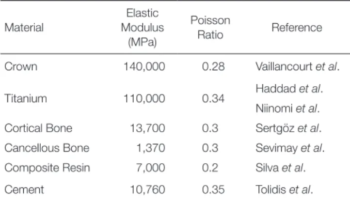
The total number of elements used for each model ranged from 3,038,810 to 3,508,862. The components of the implant system and the surrounding bone were assumed to be homogeneous, isotropic, and linearly elastic materials. The mechanical properties are presented in Table 1.18-22
To reproduce the preload from screw tightening and the masticatory forces, the FE analysis was performed as a gener- al static analysis in two steps: a preloading step and a mastica- tion step. The preload was applied on the screw to approxi- mate the relationship between an abutment and an implant fixed by screws. The preload was calculated to apply a torque of 32 Ncm using a formula provided by a previous study (Fig. 2).23 After the preloading step, a total force of 200 N was applied to each of the 60 nodes on 3 cusps and 3 fossae in the vertical direction (Fig. 2). During the two steps, both ends of the bone block were fixed in all directions at the mesial and distal surfaces of the bone.
For the interaction conditions, the abutment and implant were tightly connected by screw tightening (Fig. 3). The inter- action conditions used in the analysis included two sets of contacts: Contact 1 of the CLF implant was the contact sur- face between the resin layer and the abutment with a friction coefficient of 0.25 and Contact 1 of the CR implant was a fully bonded cement layer-abutment interface. Contact 2 was the contact surface between the abutment and implant with a friction coefficient of 0.16.24-26 Contact analysis ensured the transfer of load and deformation between the titanium-tita-
Table 1. Mechanical properties of the materials used in finite element models18,20-22,26
Material
Elastic Modulus (MPa)
Poisson
Ratio Reference
Crown 140,000 0.28 Vaillancourt et al.
Titanium 110,000 0.34 Haddad et al.
Niinomi et al.
Cortical Bone 13,700 0.3 Sertgöz et al.
Cancellous Bone 1,370 0.3 Sevimay et al.
Composite Resin 7,000 0.2 Silva et al.
Cement 10,760 0.35 Tolidis et al.
Fig. 2. Boundary conditions and load conditions of the finite element model. Both ends of the bone block are fixed in all directions and a total force of 200 N is applied to each of the 60 nodes on the three cusps in a vertical direction. The preload on the screw to achieve a tightening torque of 32 N·cm is represented by red arrows.
Fig. 3. The interface between the abutment and resin/cement layer (Contact 1) and between the abutment and the implant (Contact 2). For the cement layer of the cement-retained case, the interface condition with the abutment is set to the bonded condition (same as the “tie” condition).
nium interfaces and the resin-titanium interfaces.27 To simu- late perfect osseointegration, all interactions incorporating the implants and bone were simulated as tie conditions. The tie condition was also used for crown-resin/cement interfaces.
To analyze the stability of the CLF implant system com- pared with the CR implant system, we evaluated the implant components and bones by applying valid evaluation criteria.
The von Mises stress and principal stress were used to evalu- ate the stress values and distributions of the implant compo- nents. To predict the risk of microleakage and infection, the contact open (COPEN) values were calculated to analyze the gap formation at the contact surfaces.
For bone tissue analysis, the micro-strain levels in the bone surrounding the implants were evaluated by the bone remodeling thresholds, as suggested by the Frost mechano- stat hypothesis.28
The statistical analysis was performed to evaluate the effect of the different abutment geometries and the type of abutment-crown connection after testing the normality of each data using the Shapiro-Wilk test and equal variance.29-31
The implant component and the bone cylindrical part were assessed using Kruskal-Wallis H test of variance on ranks.32 All the tests were performed using 50 maximum values of each component.32 Values of P < .05 were considered to be statistically significant for each implant system in the non- parametric analysis. For multiple comparisons, the Mann- Whitney test and Bonferroni correction were adopted as post hoc testing to indicate the differences among the groups, using a 5% significance level for multiple compari- sons.32 The values of P < .008 were considered to be statisti- cally significant using Bonferroni correction because the 6 tests were performed for each comparison. All statistical analyses were performed using statistical software (SPSS ver- sion 20.0, IBM Corp., Armonk, NY, USA).
RESULTS
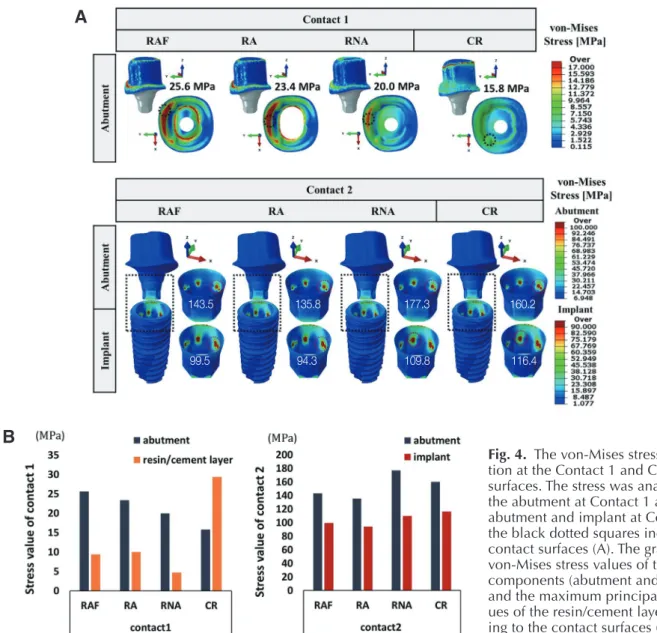
Figure 4 illustrates the stress distribution on Contact 1 and Contact 2, and the results for evaluating the influence of the implant systems are summarized in Table 2 and Table 3. The
Fig. 4. The von-Mises stress distribu- tion at the Contact 1 and Contact 2 surfaces. The stress was analyzed in the abutment at Contact 1 and in the abutment and implant at Contact 2;
the black dotted squares indicate the contact surfaces (A). The graphs of von-Mises stress values of the implant components (abutment and implant) and the maximum principal stress val- ues of the resin/cement layer accord- ing to the contact surfaces (B).
A
B
143.5 135.8 177.3 160.2
99.5 94.3 109.8 116.4
Table 2. P values of the statistical analysis of the 4 implant systems (RAF, RA, RNA, CR)* using the non-parametric Kruskal-Wallis test
Crown Resin/Cement layer Abutment Implant Cortical Bone Cancellous Bone
Gap formation
Principal stress Principal stress von-Mises stress Principal strain
max min max min C-1** C-2** C-2** max min max min C-1** C-2**
< .001 < .001 < .001 < .001 < .001 < .001 < .001 < .001 < .001 < .001 .9† < .001 < .001
* cement-retained (CR), resin-air hole-full (RAF), resin-air hole (RA), and resin-no-air hole (RNA)
** C-1: Contact 1, C-2: Contact 2
†: value with no statistically significant difference
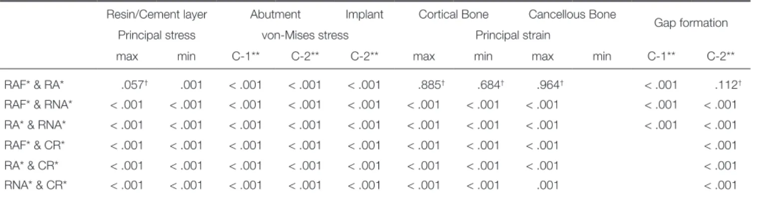
Table 3. P values of the Post hoc comparison using the Mann-Whitney U-test
Resin/Cement layer Abutment Implant Cortical Bone Cancellous Bone
Gap formation
Principal stress von-Mises stress Principal strain
max min C-1** C-2** C-2** max min max min C-1** C-2**
RAF* & RA* .057† .001 < .001 < .001 < .001 .885† .684† .964† < .001 .112†
RAF* & RNA* < .001 < .001 < .001 < .001 < .001 < .001 < .001 < .001 < .001 < .001 RA* & RNA* < .001 < .001 < .001 < .001 < .001 < .001 < .001 < .001 < .001 < .001 RAF* & CR* < .001 < .001 < .001 < .001 < .001 < .001 < .001 < .001 < .001 RA* & CR* < .001 < .001 < .001 < .001 < .001 < .001 < .001 < .001 < .001 RNA* & CR* < .001 < .001 < .001 < .001 < .001 < .001 < .001 .001 < .001
* cement-retained (CR), resin-air hole-full (RAF), resin-air hole (RA), and resin-no-air hole (RNA)
** C-1: Contact 1, C-2: Contact 2
†: value with no statistically significant difference
stress mainly occurred in the buccal direction and the CLF implant system induced much higher or similar stresses in the abutment at Contact 1. The values reflecting the maxi- mum stress of the abutment were as follows: RAF, 25.6 MPa; RA, 23.4 MPa; RNA, 20.0 MPa; CR, 15.8 MPa.
In contrast to the result for Contact 1, the maximum stresses for the CLF implant system at Contact 2 were lower or similar to those of the CR implant system, except for RNA (Fig. 4). Comparing CR with CLF in terms of the abutment surfaces, the use of abutments with no air shape induced 9% - 13% higher stress than CR (P < .001), while the use of abutments with an air shape induced 10.4% - 15%
lower stress than CR (P < .001). Evaluation of the von-Mis- es stress among the abutment and implant according to the abutment geometry showed that the no air group of RNA induced 9.3% - 14% higher stress than the air group (P <
.001).
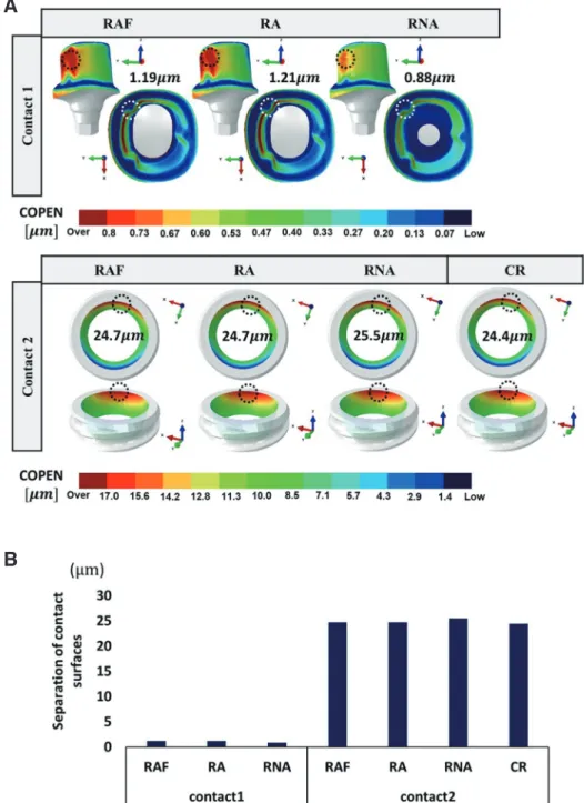
We considered the contact open (COPEN) values to ana- lyze the microleakage and infection as shown in Fig. 5, and Table 2 and Table 3 show the detailed results of the statisti- cal analysis. The COPEN values in Contact 1 (abutment-res- in interface) were measured from 0.88 to 1.19 μm, and the values in Contact 2 (abutment-implant interface) were 24.4 to 24.7 μm.
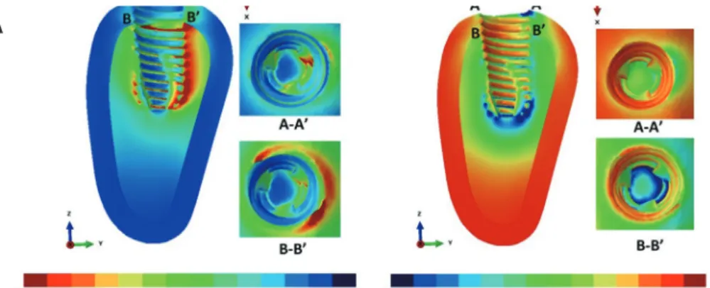
For the bone stability analysis, the micro-strains were evaluated as shown in Fig. 6. It shows the maximum and minimum principal strain distributions representing the ten- sile and compressive strains in the peri-implant bone induced by the CLF implant system and CR implant system. The strain distribution was similar in all cases, as shown in Fig.
6A. The percentage of bone volume is shown according to the strain levels in Fig. 6B. The volume over the fatigue fail- ure range was up to 0.0007% of the cancellous bone sur- rounding the implant. The results for the CLF and CR implant systems showed a similar percentage of bone vol- umes over the range of fatigue failure strain levels.
DISCUSSION
The biomechanical properties of the CLF crowns were eval- uated in this study. Comprehensive FE analysis was conduct- ed on the impact of stress on the implants and abutments and its effect on the surrounding bone.
For maximum principal stress distribution of the resin layer in Fig. 4B, the cement layer used for CR was associated with a higher risk of fracture than the resin layer, since the stress induced in association with CR (29.4 MPa) was higher than that associated with the CLF implant system (4.7 to
Fig. 5. The gap formation at contact 1 and contact 2 surfaces. The extent of the contact surface was analyzed using the COPEN values. The black and white dotted circles indicate the location of maximum COPEN value on the surface (A).
The graph of gap formation for the contact surfaces (B).
A
B
10.0 MPa). The stress value of the cement layer of the CR type was high because of the tied interaction condition among the abutment-cement-crown. As a result, the external force applied to the crown was more uniformly transmitted through the cement layer to the abutment. The 3D position between the crown and the abutment was relatively deformed by external force; for example, there was gap for- mation of up to 1.2 μm in the marginal area for the RA group as shown in Fig. 5. This indicates that the high stress
in the cement layer was influenced by the fully bonded cement between the crown and the abutment.
The contact analysis of gap formation at the implant- abutment interface was previously performed by FEA.33 There was 13 μm of gap under 100 N of vertical loading, which is comparable to 25 μm of gap under 200 N of verti- cal loading in this study. Regarding the gap formation in the marginal area of Contact 1, a small gap of less than 0.1 μm represents the stability between the crown and abutment
Fig. 6. The principal strain distribution of the bone. The surrounding bone consists of cortical and cancellous bone.
Section A-A’ is the upper surface of the cortical bone and B-B’ is the interface between the cortical and cancellous bone (A). The percentage of bone volume according to the strain levels of maximum and minimum principal strain. The cylin- drical bone parts near the implant are used for the analysis (B).
A
B
even if there is no cementation in the CLF crown. All groups showed around 25 μm of gap formation in Contact 2, which indicates that the stability of the CLF implant crowns was comparable to that of the CR implant crowns, regardless of the presence or absence of an air hole.
Strain occurred primarily in the implant thread in the buccal direction, and strains of over 1000 με were observed in the bone tissues around the implant apices. As shown in Fig. 6B, the bone volume showed overstrain (hypertrophy and fatigue failure) and ranged around 0.0012 % to 0.0013%
in the cortical bone and 0.006 % to 0.007 % in the cancel-
lous bone. Over 99% of the bone volume was ranged under 2500 με within the physiologic range. Comparison of the volume fractions according to the strain levels of bone remodeling showed that different abutment geometries or interaction conditions for the resin layer did not significantly affect the bone strain. Consequently, the strain values of the surrounding bone associated with the CLF crown were simi- lar to those of the conventional CR implant crown. For min- imum principal strain in the cancellous bone (Table 2), there was no statistically significant difference according to the abutment geometry or connection type of the crown and
resin layer (P > .008).
According to the Frost mechanostat hypothesis, a high strain level (2500 to 4000 με) stimulates remodeling activity, increases the bone density, and generates a strain level great- er than 4000 με, which induces the generation of internal cracks that result in bone failure.28 In a recent study, the bone strain around the implant was found to be 4500 με under 100 N of vertical loading, which is similar with 10,000 με of strain under 200 N of vertical loading in this study.34 Verification of the mechanostat theory in mandible remodel- ing after tooth extraction was performed through FEA and animal studies. It showed that the mechanostat theory could predict mandible remodeling after tooth extraction.35 However, there are few studies examining the proportion of strain volume. Over 4000 με on the bone surrounding the implant was below 0.001%, and overstrain could occur with- in a short period at the moment of mastication. Thus, it was assumed that the surrounding bone can be physiologically adaptive under high-strain conditions because of its small volume and the short period of mastication.
Each component, including the cement layer, consisted of numerous small elements, which assure the quality and results of the FE analysis in this study. However, this study had several limitations. Varying the direction of loading con- ditions would have resulted in a more realistic simulation.
Additional fatigue testing under cyclic loading and non-linear conditions would also have been helpful. Finally, future stud- ies with mechanical testing using the specimens are required.
CONCLUSION
The air group of the CLF implants was similar or better in terms of stability than the conventional cementation implant system. The filling of the air hole with resin in the CLF implant air group did not cause a significant difference in the stability. Also, the air hole status and the type of relining res- in did not significantly affect the stability of the cancellous bone. Thus, there were no disadvantages in terms of biome- chanical features when using the CLF system compared to the conventional CR system.
ORCID
Hyeonjong Lee https://orcid.org/0000-0002-5660-9515 Soyeon Park https://orcid.org/0000-0003-1431-2876 Kung-Rock Kwon https://orcid.org/0000-0002-9777-8980 Gunwoo Noh https://orcid.org/0000-0003-4817-7932 REFERENCES
1. Muddugangadhar BC, Amarnath GS, Sonika R, Chheda PS, Garg A. Meta-analysis of failure and survival rate of implant- supported single crowns, fixed partial denture, and implant tooth-supported prostheses. J Int Oral Health 2015;7:11-7.
2. Simonis P, Dufour T, Tenenbaum H. Long-term implant sur- vival and success: a 10-16-year follow-up of non-submerged dental implants. Clin Oral Implants Res 2010;21:772-7.
3. Staubli N, Walter C, Schmidt JC, Weiger R, Zitzmann NU.
Excess cement and the risk of peri-implant disease - a sys- tematic review. Clin Oral Implants Res 2017;28:1278-90.
4. Wittneben JG, Millen C, Brägger U. Clinical performance of screw- versus cement-retained fixed implant-supported re- constructions-a systematic review. Int J Oral Maxillofac Implants 2014;29:84-98.
5. Wittneben JG, Joda T, Weber HP, Brägger U. Screw retained vs. cement retained implant-supported fixed dental prosthesis.
Periodontol 2000 2017;73:141-51.
6. Amorfini L, Storelli S, Mosca D, Scanferla M, Romeo E.
Comparison of cemented vs screw-retained, customized com- puter-aided design/computer-assisted manufacture zirconia abutments for esthetically located single-tooth implants: A 10-year randomized prospective study. Int J Prosthodont 2018;31:359-66.
7. Lemos CA, de Souza Batista VE, Almeida DA, Santiago Júnior JF, Verri FR, Pellizzer EP. Evaluation of cement-re- tained versus screw-retained implant-supported restorations for marginal bone loss: A systematic review and meta-analy- sis. J Prosthet Dent 2016;115:419-27.
8. Lee JI, Lee Y, Kim NY, Kim YL, Cho HW. A photoelastic stress analysis of screw- and cement-retained implant pros- theses with marginal gaps. Clin Implant Dent Relat Res 2013;
15:735-49.
9. Cicciu M, Bramanti E, Matacena G, Guglielmino E, Risitano G. FEM evaluation of cemented-retained versus screw-re- tained dental implant single-tooth crown prosthesis. Int J Clin Exp Med 2014;7:817-25.
10. Tanimura R, Suzuki S. Comparison of access-hole filling ma- terials for screw retained implant prostheses: 12-month in vi- vo study. Int J Implant Dent 2017;3:19.
11. Hebel KS, Gajjar RC. Cement-retained versus screw-retained implant restorations: achieving optimal occlusion and esthet- ics in implant dentistry. J Prosthet Dent 1997;77:28-35.
12. Taylor RC, Ghoneim AS, McGlumphy EA. An esthetic tech- nique to fill screw-retained fixed prostheses. J Oral Implantol 2004;30:384-5.
13. Weininger B, McGlumphy E, Beck M. Esthetic evaluation of materials used to fill access holes of screw-retained implant crowns. J Oral Implantol 2008;34:145-9.
14. Sancho-Puchades M, Crameri D, Özcan M, Sailer I, Jung RE, Hämmerle CHF, Thoma DS. The influence of the emergence profile on the amount of undetected cement excess after de- livery of cement-retained implant reconstructions. Clin Oral Implants Res 2017;28:1515-22.
15. Gehrke P, Bleuel K, Fischer C, Sader R. Influence of margin loca- tion and luting material on the amount of undetected cement ex- cess on CAD/CAM implant abutments and cement-retained zir- conia crowns: an in-vitro study. BMC Oral Health 2019;19:111.
16. Ma S, Fenton A. Screw- versus cement-retained implant pros- theses: a systematic review of prosthodontic maintenance and complications. Int J Prosthodont 2015;28:127-45.
17. Papakostas GI, McGrath P, Stewart J, Charles D, Chen Y, Mischoulon D, Dording C, Fava M. Psychic and somatic anxi- ety symptoms as predictors of response to fluoxetine in ma- jor depressive disorder. Psychiatry Res 2008;161:116-20.
18. Vaillancourt H, Pilliar RM, McCammond D. Finite element analysis of crestal bone loss around porous-coated dental im- plants. J Appl Biomater 1995;6:267-82.
19. Bulaqi HA, Mousavi Mashhadi M, Safari H, Samandari MM, Geramipanah F. Effect of increased crown height on stress distribution in short dental implant components and their surrounding bone: A finite element analysis. J Prosthet Dent 2015;113:548-57.
20. Niinomi M. Mechanical properties of biomedical titanium al- loys. Mater Sci Eng 1998;243:231-6.
21. Sertgöz A. Finite element analysis study of the effect of su- perstructure material on stress distribution in an implant-sup- ported fixed prosthesis. Int J Prosthodont. 1997;10:19-27.
22. Tolidis K, Papadogiannis D, Papadogiannis Y, Gerasimou P.
Dynamic and static mechanical analysis of resin luting ce- ments. J Mech Behav Biomed Mater 2012;6:1-8.
23. Lang LA, Kang B, Wang RF, Lang BR. Finite element analysis to determine implant preload. J Prosthet Dent 2003;90:539-46.
24. Guda T, Ross TA, Lang LA, Millwater HR. Probabilistic anal- ysis of preload in the abutment screw of a dental implant complex. J Prosthet Dent 2008;100:183-93
25. Wang RF, Kang B, Lang LA, Razzoog ME. The dynamic na- tures of implant loading. J Prosthet Dent 2009;101:359-71.
26. Silva GC, Cornacchia TM, de Magalhães CS, Bueno AC, Moreira AN. Biomechanical evaluation of screw- and ce- ment-retained implant-supported prostheses: a nonlinear fi- nite element analysis. J Prosthet Dent 2014;112:1479-88.
27. Lee H, Park S, Noh G. Biomechanical analysis of 4 types of short dental implants in a resorbed mandible. J Prosthet Dent 2019;121:659-70.
28. Roberts WE, Sarandeep H, Jeffery AR. Bone modeling: bio- mechanics, molecular mechanisms, and clinical perspectives.
Semin Orthod 2004;10:123-61.
29. Torcato LB, Pellizzer EP, Verri FR, Falcón-Antenucci RM, Santiago Júnior JF, de Faria Almeida DA. Influence of parafunc- tional loading and prosthetic connection on stress distribution: a 3D finite element analysis. J Prosthet Dent 2015;114:644-51.
30. Santiago Junior JF, Verri FR, Almeida DA, de Souza Batista VE, Lemos CA, Pellizzer EP. Finite element analysis on influ- ence of implant surface treatments, connection and bone types. Mater Sci Eng C Mater Biol Appl 2016;63:292-300.
31. Ramos Verri F, Santiago Junior JF, de Faria Almeida DA, de Oliveira GB, de Souza Batista VE, Marques Honório H, Noritomi PY, Pellizzer EP. Biomechanical influence of crown-to-implant ratio on stress distribution over internal hexagon short implant: 3-D finite element analysis with statis- tical test. J Biomech 2015;48:138-45.
32. Minatel L, Verri FR, Kudo GAH, de Faria Almeida DA, de Souza Batista VE, Lemos CAA, Pellizzer EP, Santiago JF Junior. Effect of different types of prosthetic platforms on stress-distribution in dental implant-supported prostheses.
Mater Sci Eng C Mater Biol Appl 2017;71:35-42.
33. He Y, Fok A, Aparicio C, Teng W. Contact analysis of gap formation at dental implant-abutment interface under oblique loading: A numerical-experimental study. Clin Implant Dent Relat Res 2019;21:741-52.
34. Robinson D, Aguilar L, Gatti A, Abduo J, Lee PVS, Ackland D.
Load response of the natural tooth and dental implant: A com- parative biomechanics study. J Adv Prosthodont 2019;11:169-78.
35. Mahnama A, Tafazzoli-Shadpour M, Geramipanah F, Mehdi Dehghan M. Verification of the mechanostat theory in mandi- ble remodeling after tooth extraction: animal study and numeri- cal modeling. J Mech Behav Biomed Mater 2013;20:354-62.