THE EFFECT OF ABUTMENT HEIGHT ON SCREW LOOSENING IN SINGLE IMPLANT-SUPPORTED PROSTHESES AFTER DYNAMIC CYCLIC LOADING
Nam-Gun Kim, D.D.S., Yung-Soo Kim, D.D.S., M.S.D., Ph.D., M.Sc(O.S.U.), Chang-Whe Kim, D.D.S., M.S.D., Ph.D., Kyung-Soo Jang, D.D.S., M.S.D., Ph.D., Young-Jun Lim, D.D.S., M.S.D., Ph.D.
Department of Prosthodontics, Graduate School, Seoul National University
Statement of problem.One of the common problems of dental implant prosthesis is the loos- ening of the screw that connects each component, and this problem is more common in sin- gle implant-supported prostheses with external connection.
Purpose.The purpose of this study was to examine the changes of detorque values of abutment screws with external connection in different abutment heights.
Materials and methods.After cyclic loading on three different abutment heights, detorque values were measured.
Abutments were retained with titanium abutment screws tightened to 30 Ncm (30.5 kgmm) with digital torque gauge as recommended by the manufacturer. Replacing abutments, implants and titanium abutment screws with new ones at every measurement, initial detorque values were measured six times. In measuring detorque values after cyclic loading, Avana Cemented Abutments of 4.0 mm collar, 7.0 mm height (Osstem Co., Ltd., Seoul, Korea) were used with three different lengths of 5.0, 8.0, 11.0 mm. Shorter abutments were made by milling of 11.0 mm abutment to have the same force-exercised area of 4.5 mm diameter. Sine curve force (20N-320N, 14Hz) was applied, and detorque values were measured after cyclic loading of 2 million times by loading machine. Detorque values of initial and after-loading were measured by digital torque gauge. One-way ANOVA was employed to see if there was any influence from different abutment heights.
Results.The results were as follows :
1. The initial detorque value was 27.8±0.93 kgmm, and the ratio of the initial detorque val- ue to the tightening torque was 0.91(27.8/30.5).
2. Measured detorque values after cyclic loading were declined as the height of the abutment increased, that was, 5.0 mm; 22.3±0.82 kgmm, 8.0 mm; 21.8±0.93 kgmm, and 11.0 mm;
21.3±0.94 kgmm.
3. One-way ANOVA showed no statistically significant differences among these (p>0.05).
4. Noticeable mobility at the implant-abutment interface was not observed in any case after cyclic loading at all.
Key Words
Dental implant, Abutment, Screw loosening, Cyclic loading, Detorque value
J Korean Acad Prosthodont : Volume 42, Number 6, 2004
S
ince Bra�nemark and his colleagues had intro- duced the concept of osseointegration,1dental implant has been successfully used for edentulous patients. The use of single endosseous osseoin- tegrated implant to support dental replacement has continued to increase and become refined.However, prosthetic problems such as screw loosening, fracture, and other component failures have been observed during a long period of fol- low up.
In a multi-center study, Laney et al2 placed single-implant prostheses in 82 patients and screened them for three years. They recorded several types of complications, such as abut- ment screw fracture, soft tissue penetration, mucosal inflammation and screw loosening.
One of the common problems of dental implant prosthesis is the loosening of the screw that con- nects each component, and the problem is espe- cially more common in single implant-support- ed prostheses with external connection.3-6When it occurs, patients complain soreness at the inter- face between soft tissue and the implant, swelling and/or fistula formation, difficulty in chewing, and prosthetic instability as a results of a poor fit in the interface zone of the prosthesis and the implant.7 Fastening the screw inside the implant body results in a secure butt-joint connection between the prosthesis and the implant. This connection produces a load, which is known as preload.8 A properly preloaded abutment screw should be strong enough to resist torques from occlusal loadings for implant-supported prostheses.
However, according to several reports, screw have loosened in 1 to 57 percent of single-tooth implant restorations.9-16
Reasons for loosening include inadequate pre- load, inappropriate implant position, inadequate occlusal scheme or crown anatomy, variations in hex dimension coupled with equal variations in
the abutment counterparts, slight differences in fit and accuracy, tension on abutment and cylin- der from ill-fitting restorations, improper screw design, and excessive occlusal forces.7,17,18
While there have been many experiments on screw loosening, but not many studies on verti- cal cantilever. The purpose of this study was to examine the changes of detorque values of abut- ment screw with external connection in different abutment heights by performing comparative analysis of detorque values. After cyclic load- ing on three different abutment heights, detorque values were measured to find the differences among heights.
In this protocol, 3 assumptions19were necessary:
(1) the abutment screws were all loaded with the same preload after initial tightening, (2) the detorque value was a measure of the remain- ing preload in the abutment screw, and (3) any dif- ferences in the detorque value from specimen to specimen after fatigue testing were related to abutment height between three specimens.
MATERIALS AND METHODS 1. MATERIALS
(1) Implant
Twenty four Avana Self Tapping Implant, machined surface (Osstem Co., Ltd., Seoul, Korea)
∅4.0×11.5 mm were used (Fig. 1).
(2) Abutment screw
Twenty four titanium screws (Osstem Co., Ltd., Seoul, Korea) were used (Fig. 1).
(3) Abutment
Avana Cemented Abutments of 4.0 mm collar, 7.0 mm height (Osstem Co., Ltd., Seoul, Korea) were used with three lengths of 5.0, 8.0, 11.0 mm. 11.0 mm abutment was milled for 5.0, 8.0 mm
- lengthened abutments to have the same force- exercised area of 4.5 mm diameter (Fig. 1).
(4) Loading machine (Fig. 2)
Mini Bionix II Test System (MTS; MTS sys- tems corp., Eden Prairie, Minnesota, U.S.A.) was used under constant temperature (18℃) and constant humidity (38%) condition.
(5) Customized jig
The jig was customized by the ISO standard20) so
that the force could be applied to the abutment at 30 degrees to the long axis (Fig. 3).
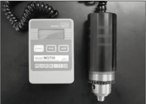
(6) Torque gauge
Detorque values were measured by digital torque gauge (MGT50, MARK-10 corp., U.S.A., Fig.
4), of which details were as follows; maximum measurement was 580 kgmm, scale was 0.5 kgmm, measurement error was 0.5%. Measured
Fig. 1.Implant, abutment screw and abutment (11.0mm, 8.0mm, 5.0mm).
Fig. 2.Loading machine.
Fig. 3.Mold for cyclic loading test. Fig. 4. Digital torque gauge.
values were converted to Ncm, if necessary, on the basis of 1.0 kgmm = 0.98 Ncm.
2. METHODS
(1) Tightening torque
Abutments were retained with titanium abut- ment screws tightened to 30 Ncm (30.5 kgmm) with digital torque gauge as recommended by the manufacturer.
(2) Initial detorque value
Initial detorque values were measured six times by digital torque gauge, replacing implant, abut- ment screw, and abutment with new ones each time.
(3) Detorque value after cyclic loading The each test assembly (abutment, abutment screw, implant) was mounted on the customized jig in MTS loading machine. A testing device delivered dynamic sine curved loading forces between 20 and 320 N at 14 Hz for 2 million cycles (Fig. 5), or the approximate equivalent of 2 years in vivo mastication.
Identical experiments were repeated for each abutment group for six times with new implant and abutment screw each time. Abutments were replaced when necessary.
(4) Statistical Analysis
SPSS statistical Software for Windows (release 10.0, SPSS Inc., Chicago, U.S.A.) was used for statistics analysis. One-way ANOVA was employed to see if there was any influence from different abutment heights (p<0.05).
RESULTS
1. Initial detorque value
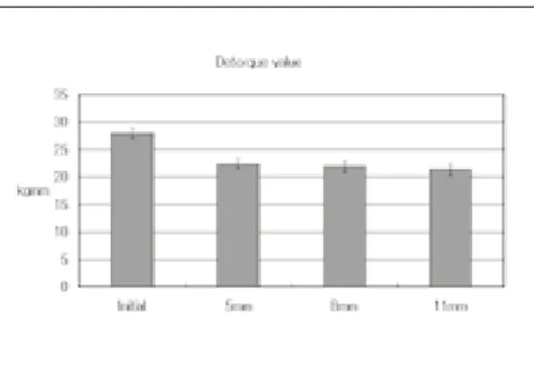
The average initial detorque values was 27.8±
0.93 kgmm (Fig. 6), and the ratio of the initial detorque value to the tightening torque was 0.91(27.8/30.5).
2. Detorque value after cyclic loading
Measured detorque values were declined as the height of the abutment increased, that was, 5.0 mm ; 22.3±0.82 kgmm, 8.0 mm was 21.8±0.93 kgmm, 11.0 mm was 21.3±0.94 kgmm (Fig. 6).
Fig. 5. Loading pattern.
Fig. 6. Initial detorque value and detorque value after cyclic loading.
Detorque value ratios to the tightening torque after cyclic loading were 0.73(22.3/30.5), 0.71(21.8/30.5), and 0.70(21.3/30.5) for 5.0 mm, 8.0 mm, and 11.0 mm, respectively.
One-way ANOVA showed no statistically sig- nificant differences among different abutment heights (p>0.05). Noticeable mobility at the implant-abutment interface was not observed in any case after cyclic loading at all.
DISCUSSION
Becker et al14)presented the results of a retro- spective analysis, which represented the first report of replacing single molars with implant-sup- ported prostheses. Loosening of the screws was the main complication. And screw loosening may be an early warning sign of biomechanical design problems or occlusal overload.21
Rangert et al22)described the implant as a system with compensating forces and a lever arm, with the axial forces and bending moments being the main types of loads acting on the implant-sup- ported prosthesis. Axial forces are more favorable, and a bending moment tends to produce rotation of a rigid body. Geometric load factors as risk fac- tors for implants in the posterior partially eden- tulous segment are (1) number of implants less than support value, (2) fewer than three implants, (3) implants connected to natural teeth, (4) implant in a line, (5) cantilever extension, (6) occlusal plane aside implant heads, and (7) excessive height of crown-abutment complex.
Screw loosening in single tooth replacement with external connection can be overcome by modification of the implant-abutment inter- face.18,23-25 However, because screw loosening in all systems can be occurred, screw hole can be pre- pared on the occlusal surface against screw loos- ening even in case of cementation type crown. Also, anti-rotational features, gold screws, torque-con- trolling mechanisms, and screw cements are rec-
ommended.7,18,26
Especially in external connection, the opera- tor must minimize the buccolingual and mesiodis- tal dimensions to reduce the cantilever,27shorten the non-functional cusps, and minimize cusp angle, choose a wide implant to reduce the lever arm. And the operator must select an abutment with zero-degree rotation between implant hex and abutment to resist the rotational forces exerted on the crown. In the case of a single anterior implant, occlusal adjustments should be carried out in such a way that the shim stock is lightly in con- tact during maximum intercuspation and no contact during lateral excursions. Despite these efforts, loosening of screws can still be a problem.
Bickford28described the process of screw loos- ening in 2 stages. Initially, external forces, such as mastication, applied to the screw joint caused thread slippage, contributing to release of the stretch, or preload, of the screw. The second stage of loosening involved continual preload reduction below a critical level, allowing threads to turn and loss of intended screw joint func- tion. If the screw loosens and the preload falls below a critical level, joint stability may be com- promised and potentiate clinical failure. On the other hand, Lee et al29 reported that the wave mode was divided into 4 stages for loosened screws: initial displacement, initial vibration, elastic deformation, and recovery stage and that the initial displacement and initial vibration stages were not discernible for stable screws.
According to Gibb et al,30 about 1 million mas- ticatory movement occurs a year. In this study, two million cyclic loading was equivalent to the mas- tication of two years, and 300 N force in this study was the amount of masticatory force gen- erated at premolar.
When initial tightening torques were applied, torque controller or torque wrench could gener- ate some deviations from the exact target value.
Therefore, digital torque gauge was used for
tightening to minimize these tightening torque errors in this study. Because repetitive use of implant and abutment screw can change the screw surface affecting the detorque values, new components were used for each experiment.
Clinically, crowns for cementation tend to be dis- located more easily as abutment height lowers.
However, the authors mounted loading on abut- ment itself without crown cementation, with- out considering cementation effects.
The initial and after-loading detorque values of all the screw joints were less than the tightening torque and the ratio of the initial detorque value to the tightening torque was 0.91. These results are consistent with the finding of Schulte et al.31
According to Weinberg et al,32a comparative evaluation of torque at the gold screw, abut- ment screw, and implant was calculated for cus- pal inclination, implant inclination, and hori- zontal and vertical implant offset. The results facilitated rational clinical conclusions that cus- pal inclination produces the most torque, fol- lowed by maxillary horizontal implant offset, while implant inclination and apical implant offset produce minimal torque. But these datas are not intended as a quantitative analysis.
In this study, there were no statistically sig- nificant differences between different abutment heights, which implied that crown height did not have any significant impact on abutment screw loosening for clinically popular crown heights (5.0 mm, 8.0 mm, 11.0 mm). However, since abutment screw loosening tended to grow as crown height increased, additional studies might be focused on the cases of extraordinary crown heights in the near future.
CONCLUSION
Initial detorque values were measured and detorque values after cyclic loading were measured for three different abutment heights (5.0 mm,
8.0 mm, 11.0 mm) to see the effects of abutment heights in single implant-supported prostheses with external connection and the results were as follows.
1. The initial detorque value was 27.8±0.93 kgmm, and the ratio of the initial detorque val- ue to the tightening torque was 0.91.
2. Detorque values after cyclic loading were 22.3
±0.82 kgmm (5.0 mm height of abutment), 21.8
±0.93 kgmm (8.0 mm), and 21.3±0.94 kgmm (11.0 mm). The ratios of the detorque value after cyclic loading to the tightening torque were 0.73, 0.71, and 0.70 for 5.0, 8.0 and 11.0 mm respec- tively, with no statistically significant differences (p>0.05).
3. Noticeable mobility at the implant-abutment interface was not observed in any case after cyclic loading at all.
It can be concluded that abutment screw loos- ening did not occur at commonly used single implant-supported prostheses heights (5.0 mm, 8.0 mm, 11.0 mm) with external connection for two years’masticatory movements. However, it is con- sidered that studies with more various loading con- ditions are necessary in the future.
REFERENCES
1. Adell R, Lekholm U, Bra�nemark PI. A 15-year study of osseointegrated implants in the treat- ment of the edentulous jaw. Int J Oral Surg 1981;10 :387-416.
2. Laney WR, Jemt T, Harris D, Henry PJ, Krogh PH, Polizzi G et al. Osseointegrated implants for single-tooth replacement: progress report from a multicenter prospective study after 3 years. Int J Oral Maxillofac Implants 1994;9:49-54.
3. Binon PP. The effect of implant/abutment hexag- onal misfit on screw joint stability. Int J Prosthodont 1996;9:149-160.
4. Jemt T. Failures and complications in 391 con- secutively inserted fixed prostheses supported by Bra�nemark implants in edentulous jaws: A study of treatment from the time of prosthesis placement to the first annual checkup. Int J Oral Maxillofac Implants 1991;6:270-276.
5. Jemt T. Multicenter study of overdentures supported by Bra�nemark. Int J Oral Maxillofac Implants 1992;7:513-522.
6. Jemt T, Linden B, Lekholm U. Failures and com- plications in 127 consecutively inserted fixed pros- theses supported by Bra�nemark implants: From prostheses treatment to first annual check up. Int J Oral Maxillofac Implants 1992;7:40-43.
7. Artzi Z, Dreiangel A. A screw lock for single- tooth implant superstructures. J Am Dent Assoc 1999;130:677-682.
8. Carr AB, Grunski JB, Hurley E. Effects of fabrica- tion, finishing, and polishing procedures on pre- load in prostheses using conventional gold and plas- tic cylinders. Int J Oral Maxillofac Implants 1996;11:589-598.
9. Jemt T, Lekholm U, Grondahl K. A 3-year fol- low-up study of early single implant restorations ad modum Bra�nemark. Int J Perio Rest Dent 1990;10:341-349.
10. Jemt T, Laney WR, Harris D, Henry PJ, Krogh PH, Polizzi G et al. Osseointegrated implants for single tooth-replacement: a 1-year report from a mul- ticenter prospective study. Int J Oral Maxillofac Implants 1991;6:29-36.
11. Ekfeldt A, Carlsson GE, Borjesson G. Clinical evaluation of single-tooth restorations supported by osseointegrated implants: a retrospective study.
Int J Oral Maxillofac Implants 1994;9:179-183.
12. Haas R, Mensdorff-Pouilly N, Mailath G, Watzek G. Br?nemark single tooth implants: a prelimi- nary report of 76 implants. J Prosthet Dent 1995;73:274-279.
13. Henry PJ, Laney WR, Jemt T, Harris D, Krogh PH, Polizzi G et al. Osseointegrated implants for single tooth-replacement: a prospective 5-year multicenter study. Int J Oral Maxillofac Implants 1996;11:450-455.
14. Becker W, Becker BE. Replacement of maxillary and mandibular molars with single endosseous implant restorations: a retrospective study. J Prosthet Dent 1995;74:51-55.
15. Wie H. Registration of localization, occlusion and occluding materials for failing screw joints in the Bra�nemark implant system. Clin Oral Implants Res 1995;6:47-53.
16. Carl JD. A clinical study of the efficacy of gold-tite square abutment screws in cement-retained implant restorations. Int J Oral Maxillofac Implants 2003;18:273-278.
17. Schwarz MS. Mechanical complications of dental implants. Clin Oral Implants Res 2000;11 Suppl 1:156-158. Review.
18. Cavazos E, Bell FA. Preventing loosening of implant abutment screws. J Prosthet Dent 1996;75:566- 569.
19. Cibirka RM, Nelson SK, Lang BR, Rueggeberg FA. Examination of the implant-abutment interface
after fatigue testing. J Prosthet Dent 2001;85:268- 275.
20. ISO/DIS 14801 Dental implants-Dynamic con- tinuous fatigue test. International Organization for Standardization, 2001.
21. Jaarda MJ, Razzoog ME, Gratton DG. Geometrical comparison of five interchangeable implant pros- thetic retaining screws. J Prosthet Dent 1995;9:373- 379.
22. Rangert BR, Sullivan RM, Jemt TM. Load factor con- trol for implants in the posterior partially edentulous segment. Int J Oral Maxillofac Implants 1997;12:360- 370.
23. Balfour A, O’Brien GR. Comparative study of antirotational single tooth abutments. J Prosthet Dent 1995;7:36-43.
24. Beat RM, Stephan H, Urs CB. Mechanics of the im- plant-abutment connection: An 8-degree taper compared to butt joint connection. Int J Oral Maxillofac Implants 2000;15:519-526.
25. Norton MR. An in vitro evaluation of the strength of an internal conical interface compared to a butt joint interface in implant design. Clin Oral Impl Res 1997;8:290-298.
26. McGlumphy E. Keeping implants screws: Are we beyond retrievability. J Prosthet Dent 1994;72:628.
27. Bankaeen LG, Winkler S, Neff PA. The effect of im- plant diameter, restoration design, and occlusal table variations on screw loosening of posterior sin- gle-tooth implant restorations. J Oral Implantol 2001;27:63-72.
28. Bickford JH. An introduction to the design and be- havior of bolted joints. New York: Marcel Dekker;
1995. p.515-564.
29. Lee JS, Kim YS, Kim CW, Han JS. Wave analysis of implant screw loosening using an air cylindrical cyclic loading device. J Prosthet Dent 2002;88:402- 408.
30. Gibb CH, Mahan PE, Mauderli A, Lundeen HC, Walsh EK. Limits of human bite strength. J Prosthet Dent 1986;56:226-229.
31. Schulte JK, Coffey J. Comparison of screw reten- tion of nine abutment systems: a pilot study.
Implant Dent 1997;6:28-31.
32. Weinberg LA, Kruger B. A comparison of im- plant/prosthesis loading with four clinical variables.
Int J Prosthodont 1995;8:421-433.
Reprint request to:
CHANG-WHE KIM
DEPARTMENT OFPROSTHODONTICS,GRADUATESCHOOL, SEOULNATIONALUNIVERSITY,
28, YEONGUN-DONG,CHONGNO-GU, SEOUL,110-744, KOREA [email protected]