*정회원, 한세대학교 IT학부
접수일자 : 2014년 6월 2일, 수정완료 : 2014년 10월 11일 게재확정일자 : 2014년 12월 12일
Received: 2 June, 2014 / Revised: 11 October, 2014 Accepted: 12 December, 2014
*Corresponding Author: [email protected] School of IT, Hansei University, Korea http://dx.doi.org/10.7236/JIIBC.2014.14.6.251
JIIBC 2014-6-36
가변부하를 갖는 선형 증폭기를 구동하기 위한 전압적응 변환기용 전력공급기 개발
Development of Power Supply for Voltage-Adaptable Converter to Drive Linear Amplifiers with Variable Loads
엄기홍
*Kee-Hong Um
*요 약 모터의 일종으로서 엑츄에이터는 전기 에너지를 운동 에너지로 변환하기 위하여 전류를 이용하여 동작하는 메 커니즘을 제어하는 시스템이다. 전압을 가청 신호로 변환하는 기능을 갖는 오디오 액츄 에이터로서는 스피커와 증폭기 가 흔히 사용된다. 산업 현장에서는 고출력 고양질의 전력 시스템이 필요하다. 이러한 시스템들이 품질이 좋은 출력을 생성하기 위하여 오디오 시스템의 출력 임피던스를 제어해야 만 한다. 우리는 이 논문에서 가변 부하가 연결되어 있는 능동 증폭기 시스템을 구동하기 위한 적응 특성을 전력 공급기를 제시한다. 전기 신호를 오디오 신호로 변환하는 스피 커의 저항값이 변동함에 따라 능동 증폭기에 대한 전력 공급 장치는 부하값의 변동에 적응하여 스피커에 최대 전력을 공급하며, 피크전류의 급격한 변동과 과잉전류의 흐름으로부터 증폭기를 보호하게 된다.
Abstract
An actuator system is a type of motor designed to control a mechanism operated by a source of energy, in the form of an electric current by converting energy into some kind of motion. As audio actuators, transforming electric voltage signal into audio signal, speakers and amplifiers are commonly used. In applications of industry, high output power systems are required. For these systems to generate high-quality output, it is essential to control output impedance of audio systems. We have developed an adaptable power supply for driving active amplifier systems with variable loads. Depending on the changing values of resistance of the speaker which produces audible sound by transforming electric voltage signal, the power supply source of the active amplifier can generate the maximum power delivered to the speaker by an adaptable change of loads. The amplifier is well protected from the abrupt increment of peak current and an excess of current flow.Key Words :
Audio Actuators, High-power Amplifiers, Loud Speakers, Voltage Converter, EEPROMI. Introduction
An actuator is a mechanism used in the manufacturing of machines and equipment to initiate valves required to stop or start a function. An
important part in machines, such as computer-operated
machines or audio equipment, actuators can use fluid,
air or electric current to facilitate motion. Actuators
generally fall in one of two categories: acoustic system
or haptic system
[1]. As audio (acoustic) actuators,
transforming electric voltage signal into audio signal, speakers and amplifiers are commonly used. In applications of industrial areas, power systems to produce high output are required. Recently, due to the mechanical and electrical solidarity, and noise characteristics of immunity, amplifier designed with linear circuits is well preferred. Therefore, a technique of series or parallel driving of two sources combined are introduced in order to supply the varying values of power. By this configuration, when the lower power is required, the two voltage sources are connected in parallel and when the higher power is required, the two voltage sources are connected in series. This driving system designed by combining two sources is useful for generating high power in a short transient time, but not so recommended in the case when the constant values of high power is required in order to generate a delicate or subtle
quality of output sound in SPL (sound pressure level). To overcome these limitations, development of high-power amplifiers for the high-efficiency audio output has been studied
[2]. SPL is defined in order to represent the strength of sound. It compares a certain sound level
with respect to the reference sound level
as
In Eq.(1), a sound level
is in ×
[μbar] in CGS unit and ×
[N/㎡] in MKS unit. The unit of sound pressure in SI unit is PA (pascal), and the unit of SPL is in dB. Many kinds of amplifiers, including linear and digital amplifiers, have been developed. Due to the mechanical and electrical solidarity, amplifying properties, and noise properties, the linear amplifier with variable source is preferred
[3]. The power supply of variable active amplifier protects the amplifier from abrupt peak value of current and excessively supplied
current by controlling the supply voltage source, detecting the peak value of current through the amplifier and average supply value. We have found out that the proposed system supplies power for driving active amplifier systems with variable loads in order to produce maximum output. We propose a maximum power supply for driving active amplifier systems with variable loads in order to transfer maximum output
[4]. Regardless of load resistors at the output terminal of audio systems, the system is designed so that the voltage source in the input terminal is adaptively operating in order to supply power for the normal conditions of operation. The system we propose is partly composed of ac power supply #1 (composed of two voltage sources connected in parallel), dc power supply #2 (composed of positive and negative source transformers, a data table, and a controller), and amplifier. Some of characteristics of the system we propose can be given below.
II. Speaker System
A loudspeaker (or simply "speaker") is an electroacoustic
transducer that produces sound by transforming an
input electrical signal into output voice signal
[5]. To
adequately reproduce an audio signal with a wide range
of frequencies, most loudspeaker systems employ more
than one driver, particularly for higher sound pressure
level or maximum accuracy. In order to reproduce
different frequency ranges, individual drivers are
introduced. Audio signals have frequencies in the audio
frequency range of roughly 20 to 20,000Hz (the limits
of human hearing). Audio signals may be synthesized
directly, or may originate at a transducer such as a
microphone, musical instrument pickup, phonograph
cartridge, or tape head. Loud speakers or headphones
convert an electrical audio signal into sound. Digital
representations of audio signals exist in a variety of
formats. The speaker two-dimensional PVDF in the
forms of blown film and casting film adopted is well
operated
[6]. For the system operating with high power,
the corresponding amplifier to be used should be a one with a reasonable high power. The output of high power amplifier depends on the value of impedances. If the load impedance of speaker is increased, the output of audio amplifier is decreased. If the impedance of speaker load is decreased, the current through the voltage source is limited so that the output of audio amplifier is decreased. There have been many researches in order to develop the amplifier for the output of audio systems with high efficiency
[7]. Based on these researches, various amplifiers with digital properties have been developed. Because of the solidarity, stability, noise immunity, and excellent performance, the amplifiers with linear amplifying circuits are preferably adopted. Currently, amplifiers with variable source circuits are commercially available. As a good example there is a system composed of two voltage sources connected in series and parallel in order to generate the maximum power available. In order to generate a lower power, the source voltage should be decreased, and for higher power the two voltage sources are connected in series.
Since the sources are operated in two ways, with small values of loads and larger value of loads, it is useful when the power is generated instantaneously or when the maximum peak power is required. But when the generation of high power with consistent level is required for producing a sound of high quality, the speaker and amplifier should be designed for a better performance. In this paper, we show the design of power supply of active amplifiers with variable loads in order to deliver a steady output power to the corresponding speaker by detecting the maximum value of current and the average value of the current in a designated time interval.
III. Power Supply of Active Amplifier
1. Amplifier circuit
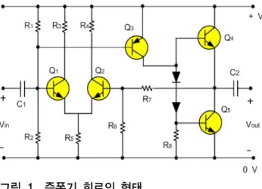
Fig 1. shows a configuration of an electronic amplifier commercially available to the electronic circuit
designer. It is referenced here for the sake of convenience. An electronic amplifier is an electronic device that increases the power of an input signal. The operation of an amplifier is designed to take energy from a power supply and controlling the output to match the input signal shape but with a larger amplitude. In this respect, an amplifier modulates the output of the power supply. Amplifiers are described according to their input and output properties
[8].
Amplifiers exhibit the property of gain, or multiplication factor that relates the magnitude of the output signal to the input signal. The gain of amplifier can be defined as : the ratio of output voltage to input voltage as a voltage gain , output power to input power as a power gain, or some combination of current, voltage, and power. With input and output in the same unit, gain had no units. Frequently, the gain is expressed in decibels
[9].
그림 1. 증폭기 회로의 형태
Fig. 1. Configuration of amplifier circuit
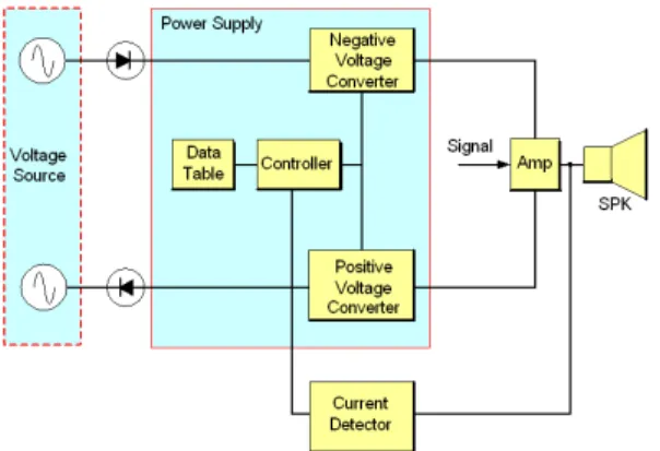
2. Power supply of active amplifier circuit Fig 2. shows a block diagram of power supply of active amplifier with variable load. The main devices of the system are voltage converter for power conversion, data table, and controller
[10]. The power conversion is the operation s of converting electric energy from one form to another, converting between AC and DC, or just changing the voltage or frequency, or some combination of these
[11].
The controller receives supply voltage data from
data table corresponding to the load resistances, and
transmits the control signal to the voltage converter so
ResistanceΩ 2.00 4.00 6.00 8.00
Voltage Supplied(V)
67.25 93.00 115.00 13.00
Peak Current Supplied(A)
31.60 22.00 18.25 15.00
Average Current Supplied(A)
10.00 7.10 5.80 5.00 표 1. 데이터 테이블에 저장된 저항, 공급전압, 피크 공급 전
류, 평균 공급전류
Table 1. Values of resistance, voltage, peak current, average current stored in data table.
that the source data can be delivered to the loads. The controller can be implemented by microprocessors and micro controllers integrated with surrounding circuits.
It receives the values of load resistances of the speaker and obtain the supply voltage from the data table in order to produce the maximum output corresponding to the load resistances. The voltage converter is implemented by SMPS (switch mode power supply) or dc/dc converter. An SMPS is an electronic power supply device that has a switching regulator in order to convert electrical power.
그림 2. 가변 부하를 갖는 능동형 증폭기에 대한 전력 공급기 의 블록도
Fig. 2. Block diagram of power supply of active amplifier with variable load
In the same fashion with the other power supplies, it transfers electrical power from a source to a load while converting voltage and current characteristics.
Unlike a linear power supply, the pass transistor of a switching-mode supply continually switches between low-dissipation, full-on and full-off states, and spends very little time in the high dissipation transitions, which minimizes wasted energy. An ideal switched-mode power supply dissipates no power.
Depending on the output from the signal controller, the relevant voltage transformer is activated in order to operate amplifier connected to the audio actuator. The positive voltage converter receives the positive components of voltage source and transforms to the supply voltage for the amplifier according to the control signal. The negative voltage converter receives the
negative components of voltage source and transforms to the supply voltage for the amplifier according to the control signal. The data table is stored in the EEPROM (Electrically Erasable Programmable ROM) or flash memory, as a type of non-volatile memory allowing data to be written to each address by way of electric signals.
In case when larger amount of static data is required to be stored (such as in USB flash drives) a specific type of EEPROM such as flash memory is more economical in capacity than traditional EEPROM devices. EEPROMs are realized as arrays of floating-gate transistors
[12]. The data include the supply voltage for the maximum power transfer, instantaneous maximum currents, and the average current in specified time duration, depending on the load values of speaker. The access to the stored data is determined by the controller.
Table 1 shows an example of data set stored in the
data table power supply of active amplifier with
variable load. As shown in the table, the data table
includes the resistance of speaker, supply voltage for
the maximum output, instantaneous peak current, and
the average current in a time interval. Each of the
values of voltage supplied, peak current supplied ,and
the average current supplied are chosen in order to
produce the maximum SPL (sound pressure level)
relevant to each of the resistor values
[13].
Ⅳ. Positive Voltage Converter
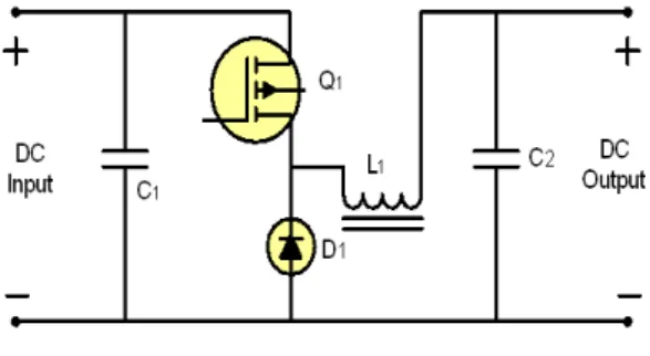
Fig 3. shows the circuit diagram of positive voltage converter. As shown in the figure, the voltage converter includes capacitor (C1), transistor, diode, inductor, and capacitor (C2). The controller determines the output voltage by controlling the periods of ON/OFF operations of transistor. The controller receives the current form the current detector. If the instantaneous peak value of the current exceeds the maximum tolerance of the data stored in the data table, it controls the amount of current through the voltage converters.
그림 3. 양극 전압 변환기 형태
Fig. 3. Diagram of positive voltage converter
Fig 4. shows the output power from the positive voltage converter. The ON/OFF frequencies of the switching operations are determined by the controller
[14].
1. The signal of ac power supply is rectified into dc signal by two diodes. The rectified power signal is applied to the two of positive and negative voltage transformers. The voltage transformer is so designed that the audio actuator (speaker) can generate the maximum sound level of 75 [dB] (in SPL, sound pressure level) independent of resistor values connected to the amplifier. The power supply is designed to control the current through the speaker.
2. The voltage transformer is implemented by
SMPS(switch mode power supply) or dc/dc buck converter
[15]. Depending on the output from the signal controller, the relevant voltage transformer is activated in order to operate amplifier, connected to the audio actuator.
3. The power supply of variable active amplifier protects the amplifier from abrupt change of peak value of current and excessively supplied current by controlling the supply voltage source, and detecting the peak value of current through the amplifier and average supply value.
그림 4. 양극 전압 변환기의 출력 전압
Fig. 4. Output power from the positive voltage converter
Ⅴ. Conclusions
By adopting the voltage source corresponding to the
load resistance of the actuator speaker, the system we
propose can produce the maximum power of the
speaker independent of the load resistance connected to
the amplifier. Regardless of load resistors at the output
terminal of audio systems, the system is designed so
that the voltage source in the input terminal is
adaptively operating in order to supply power for the
normal conditions of operation. The power supply
connected to the active amplifier with variable load
detects and controls the peak and the average values of
the current through the amplifier. We verified that due
to this operation, the amplifier is well protected from
the abrupt increment of peak current and an excess of
current flow.
Acknowledgements : The author wishes to express his thanks to Drs. Kwan-Woo Lee (Osung Mega Power Co., Ltd.) and Soo-Yeup Yoo (Amotech Co., Ltd.). Without their help and guidance, this work would have been impossible to complete.
Remarks : This work is modified, extended, and advanced from the conference presentation at ICAE 2013, International Conference on Advanced Electromaterials, Nov. 12 until Nov. 15, 2013, Jeju Island, Korea.
References
[1] http://www.ehow.com/about_6175352_types-actuators.
html#ixzz33DqEnjeY
[2] R. Matz, D. Götsch, R. Karmazin, R. Männer, and B.
Siessegger, JECR vol. 22, Issue 1-3, pp. 209-215, 2009.
[3] D. L. Sharpin, “Analysis of the linear amplifier/
analog-digital converter interface in a digital microwave receiver”. IEEE Transactions on Aerospace and Electronic Systems, vol. 31, Issue 1, pp. 248–256, Jan. 1995.
[4] R. C. Jaeger, Microlectronic Circuit Design, WCB/McGraw-Hill, New York, p. 354, 1997.
[5] J. J. Im, “Development of energy expenditure measurement device based on voice and body activity”. Journal of the The Institute of Internet, Broadcasting and Communication, vol. 12, no. 6, pp. 303-309, Dec. 2012.
[6] M. S. Choi, “A Study on the Elongation of Polymer Extrusion Film”, The Journal of the Korea Academia-Industrial cooperation Society, Vol. 15, No. 2, pp. 660-665, Feb. 2014.
[7] N. O. Sokaland A. D. Sokal, “Class E – A New Class of High-Efficiency Tuned Single-Ended Switching Power Amplifiers”, IEEE Journal of Solid-State Circuits, vol. 10, Issu. 3, 168-176, 1975.
[8] R. Boylestad and L. Nashelsk, Electronic Devices and Circuit Theory, 7th Edition. Prentice Hall, College Division. ISBN 978-0-13-375734-7, p. 765, 1996.
[9] Patronis, Gene “Amplifiers”. In Glen Ballou.
Handbook for Sound Engineers: The New Audio Cyclopedia. Howard W. Sams & Co. p. 493. ISBN 0-672-21983-2. 1987.
[10] E. Lefeuvre, A. Badel, C. Richard, D.Guyomar,
“Energy harvesting using piezoelectric materials:
Case of random vibrations”, Journal of Electroceramics, vol. 19, Issue 4, pp.349-355, 2007.
[11] Carazo, Alfredo Vázquez; Uchino, Kenji. “Novel Piezoelectric-Based Power Supply for Driving Piezoelectric Actuators Designed for Active Vibration Damping Applications”, Journal of Electroceramics vol. 7, Issue 3, p. 197-210, Dec.
2001.
[12] N. Mohan, T. M. Undeland, W. P. Robbins.
Power Electronics: Converters, Applications and Design, Wiley, New York, 2002.
[13] K. H. Um, “Output Improvement of Two-dimensional Audio Actuators by Corona Surface Treatments to Increase Adhesive Properties of Piezoelectric Materials”, Journal of the The Institute of Internet, Broadcasting and Communication, vol. 12, no. 5, pp.
91-97, Jun. 2012.
[14] M. Popescu, A. Velea, F. Sava, and A. Lőrinczi,
“Chalcogenide systems at the border of the glass-formation domain: A key for understanding the memory-switching phenomena”, Phys. Status Solidi B. doi: 10.1002/pssb.201350104, Oct. 2013.
[15] B. T. Irving, M. M. Jovanović, Applied Power
Electronics Conference and Exposition APEC
2002. Seventeenth Annual IEEE, vol. 2 , Dallas, TX,
USA, pp. 897-903, 2002.
저자 소개
Keehong Um
Academic background
∙Electronics Dept., Hanyang University (B.S.)
∙NYU (New York University), Polytechnic Institute of Engineering, Dept. of Electrical & Computer Engineering (M.S.)
∙New Jersey Institute of Technology (NJIT), Dept. of Electrical & Computer Engineering (Ph.D.)
Work experience
∙TA, RA, and Lecturer at NJIT (New Jersey, USA)
∙Researcher at RS Microwave Company Inc. (New Jersey, USA)
∙Researcher at Physics Department, Princeton University (New Jersey, USA)
∙Adjunct Professor at NJIT (New Jersey, USA)
∙Currently, Full-time Professor at IT Dept., Hansei University
<Research areas : Antennas, Microwaves, and Electro- materials