pISSN 1229-3008 eISSN 2287-6251
Progress in Superconductivity and Cryogenics
Vol.18, No.4, (2016), pp.40~43 http://dx.doi.org/10.9714/psac.2016.18.4.040
```
1. INTRODUCTION
In heavy ion accelerator system, quadruple magnets are widely used for controlling the transporting charged particles. The quadruple triplet consists of three consecutive quadrupoles. With an appropriate configuration of quadruple triplet, the beam trajectory of particles can be controlled to focus at an expected position.
Generally, the beam trajectory of charged particles is calculated by using ion optical code such as COSY infinity [1] or GICOSY [2], etc. The beam trajectory calculated by using ion optical code based on matrices has limits in representation of real beam trajectory. Because higher order fields exist in real magnet fields and ion optical code has limits in representation of real field. Therefore, it is necessary to accurately represent the beam trajectory at a certain position where there are ion optically relevant positions such as focused positions. For the first step, the beam trajectory of charged particles was calculated by using beam tracking code (Opera
TMprogram) to estimate an effect of higher order field in quadrupole triplet system.
SCALA program was used to simulate the beam trajectory in Opera
TMprogram. SCALA can analyze a large number of beam trajectories at the same time. In this paper, based on a given triplet system, ideal field was imported into the triplet model. By SCALA analysis, the range and the position of the beam spot can be obtained. Then by
changing the parameters of the triplet system with evolution strategy (ES) method [3], the focused position of beam trajectory can be controlled. Using ES method, a shorter and a longer quadruple triplet system with the expected beam spot range were suggested in this paper.
2. BEAM ANALYSIS
2.1. Triplet system
A three-dimensional quadruple triplet model for a heavy ion accelerator was analyzed in this study. The quadruple triplet which was consisted of three consecutive quadrupoles, Q1, Q2 and Q3, is used to control beam trajectory at a focused position. Q3 has the same parameters with Q1 and Q3 is symmetry with Q1 as shown in Fig. 1.
For simulating the process of the beam trajectory, the sphere surface is used as the emitter surface in the triplet system. The emitter structure is shown in Fig. 2.
Fig. 1. Mesh distribution for one fourth triplet model.
Control the length of beam trajectory with a quadruple triplet for heavy ion accelerator
Shaoqing Wei
a, Zhan Zhang
a, Sangjin Lee
*,a, Do Gyun Kim
b, and Jang Youl Kim
ba
Uiduk University, Gyeongju, Korea
b
Rare Isotope Science Project, Institute for Basic Science, Korea
(Received 11 November 2016; revised or reviewed 26 December 2016; accepted 27 December 2016)
Abstract
Beam trajectory is needed to be controlled in heavy ion accelerator system. Quadruple magnets are widely used in heavy ion accelerator for focusing the transporting particles. A quadruple triplet system which consists of three consecutive quadrupoles, Q1, Q2 and Q3, is used to control beam trajectory at a focused position. Q1 and Q3 have symmetry with respect to Q2. The beam trajectory in magnet system is affected by higher order fields existed in real fields. For quadrupoles, the representation simulation of beam trajectory was carried out to study the beam trajectory and to estimate an effect of higher order field in triplet system.
SCALA program was used to simulate the beam trajectory in Opera
TM. SCALA can analyze a large number of beam trajectories at the same time by adjusting the size of finite element of the emitter. With Opera
TMand Matlab
TMprograms, the position of focused beam spot in quadruple triplet system can be increased or decreased using evolution strategy (ES) method, therefore the length of triplet system can be controlled. Finally, the quadruple triplet system with the appropriate length and expected beam spot range was suggested in this paper.
Keyword : Beam trajectory, Beam spot, Evolution strategy, Heavy ion accelerator, The length of quadruple triplet
* Corresponding author: [email protected]
Shaoqing Wei, Zhan Zhang, Sangjin Lee, Do Gyun Kim, and Jang Youl Kim
(a) (b)
Fig. 2. Emitter of the triplet system: (a) the structure of the emitter (b) the emitter surface.
Fig. 3. Flow chart for importing magnetic flux density to the triplet model.
(a)
(b)
Fig. 4. Ideal magnetic flux density for the triplet: (a) ideal field for the triplet (b) magnetic flux density in Opera
TM.
The particle U
23879was used in the study. The ideal quadrupole field was used to study the beam trajectory in the triplet system [4]. With Opera
TMprogram and Matlab
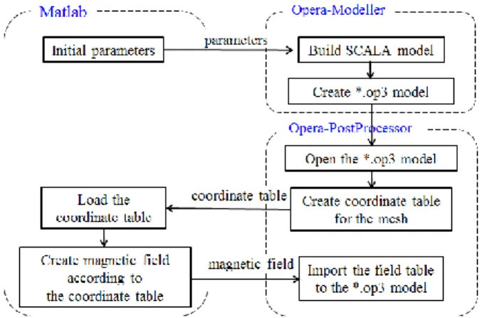
TMprogram, the magnetic flux density was imported to the triplet model [5]. The follow chart of the process is shown as Fig. 3.
Firstly, according to the dimension of the triplet system, a *.op3 database file of the triplet model is built in
Opera-Modeller program. Then, the coordinate table of the
*.op3 database model is created in Opera-PostProcessor program. Next, the field table is created according to the coordinate table in Matlab
TMprogram. Finally, the field table is imported into the *.op3 database model in Opera-PostProcessor program to create the ideal field for beam anaylsis. The higher order field also can be imported with the ideal field when the field table was created.
B distribution was checked in longitudinal direction at aperture, whose radius is 120 mm, shown in Fig. 4.
2.2. Beam trajectory of the triplet system
The beam trajectory with the ideal field is shown in Fig.
5. Fig. 6 shows the view of the beam trajectory in x and y direction. The beam spot range with respect to z axis is shown in Fig. 7.
From the result, the focused beam spot is located at z = 3400 mm. The range of focused beam spot in x direction, Xmax, is 0.2 mm, and the range of focused beam spot in y direction, Ymax, is 1.4 mm. The beam spot at the focused position z = 3400 mm is shown in Fig. 8.
Fig. 5. The beam trajectory for the triplet model.
Fig. 6. The view of the triplet beam trajectory in x direction and in y direction.
32000 3250 3300 3350 3400 3450 3500 2
4 6 8 10
Beam sp o t ran g e (mm)
z axis (mm) Beam spot range
Xmax Ymax
Fig. 7. Beam spot range with respect to z.
41
Control the length of beam trajectory with a quadruple triplet for heavy ion accelerator
Fig. 8. Beam spot at focused position.
3. THE FOCUSED LENGTH CONTROLLING
To control the focused position, the parameters of the triplet system were defined as the following:
a) B1 and B2 are the magnetic flux density of Q1 and Q2.
b) L
1effand L
2effare the effective length of Q1 and Q2.
c) C
1and C
2are the center coordinates of Q1 and Q2.
By adjusting the defined parameters of the triplet system, the appropriate triplet model with the expected beam range of beam spot and beam spot position can be obtained.
Fig. 9 shows the flow chart to adjust these parameters and to control the length of beam trajectory.
3.1 Decrease the length of beam trajectory
The position of focused beam spot in triplet can be decreased by ES method.
The purpose in this section is to find appropriate design variables x = [B1, B2, L1
eff, L2
eff, C1, C2]
Tand minimize the object function OF1
Z
FOF1 (1)
where Z
Fis the beam focused position. The constraint is set as
1 Ymax
1
Xmax (2)
Fig. 9. Flow Chart for controlling the triplet system length.
TABLE I
R
ESULT FORS
HORTERT
RIPLETM
ODEL.
Fig. 10. Result for the shorter triplet model.
3100 0 3150 3200 3250 3300 3350 3400 10
20 30 40
Beam sp o t ran g e (mm)
z axis (mm)
Beam spot range in the shorter triplet
Xmax Ymax
Fig. 11. Focused beam spot in the shorter triplet model.
Fig. 12. The beam spot at the focused position in shorter triplet model.
After using ES method, a shorter triplet is obtained. The position of the focused beam spot is decreased to 3178 mm.
The results and the parameters of the shorter triplet are shown in Table I.
The beam trajectory of the particles for the shorter triplet was shown in Fig. 10. The beam range with respect to z axis is shown in Fig. 11. At z = 3178 mm the maximum range of the focused beam is 0.41 mm in x direction and 0.51 mm in y direction. The beam spot at the focused position z = 3178 mm is shown in Fig. 12.
Model Variables
Z
FXmax Ymax [B1, B2, L1
eff, L2
eff, C
1, C
2]
Initial
model [1.4516,-0.8796,550,900,775,1700] 3400 0.196 1.425 Shorter
model [1.4579,-0.8786,561,886, 386,1356] 3178 0.41 0.51
42
Shaoqing Wei, Zhan Zhang, Sangjin Lee, Do Gyun Kim, and Jang Youl Kim
3.2 Increase the length of beam trajectory
Using ES method, the position of focused beam spot in triplet also can be increased. Because of the shape of emitter, the longer focused position is more difficult to get for the triplet system. Therefore the design variables are reduced in this section.
For each quadrupole, the produce of the effective length and the magnetic flux density are considered as a constant for reducing the design variables. The constants are got from the initial model shown in (3). Therefore, the design variables are reduced to x = [L1
eff, L2
eff, C1, C2]
T.
791.64 900
8796 . 0 2 2
798.38 550
4516 . 1 1 1
eff eff
L B
L
B (3)
B1 and B2 can be obtain from (3)
eff eff
2 791.64/
2
1 798.38/
1
L B
L B
(4)
The object function OF2 is given as
1/Z
FOF2 (5) The used constraint is
2 Ymax
2
Xmax (6)
Because of the shape of the emitter, the constraint is a little increased to get the longer triplet system. After using ES method, a longer triplet is obtained. The position of the focused beam spot is increased to 3445 mm. The results and the parameters of the longer triplet are shown in Table II. From (4), B1 is equal to 1.1104 T and B2 is equal to -0.8712 T.
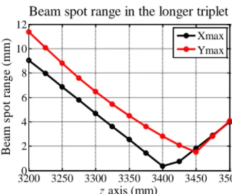
The beam trajectory of the particles for the longer triplet was shown in Fig. 13. The beam range with respect to z axis is shown in Fig. 14. At z = 3445 mm the maximum range of the focused beam in x direction and in y direction is 1.58 mm and 1.60 mm respectively. The beam spot at the focused position z = 3445 mm is shown in Fig. 15.
TABLE II
R
ESULT FORL
ONGERT
RIPLETM
ODEL.
Fig. 13. Result for the longer triplet model.
32000 3250 3300 3350 3400 3450 3500 2
4 6 8 10 12
Beam sp o t ran g e (mm)
z axis (mm)
Beam spot range in the longer triplet
Xmax Ymax