Introduction
Facial asymmetry has been analyzed on a posterior-ante- rior cephalometric radiograph. The length measurement between a midsagittal line and menton or the angular mea- surement between a midsagittal line and a line passing through menton has been used to determine the severity
of mandibular asymmetry.1-4Two dimensional (2D) imag- ing of three dimensional (3D) human face inevitably creates superimposition and dimensional changes or distortion of anatomic structures. Two dimensional imaging is determin- ed by the relative position of an object, X-ray source, and image receptor, so that the viewing angle is limited by the projection of radiation through the object to the image re- ceptor.
Three-dimensional analysis of facial asymmetry using computed tomography (CT) has been introduced by some researchers.5-13 Three dimensional computed tomography enables accurate measurements of lines and angles without image distortion and magnification, providing various
Application of spherical coordinate system to facial asymmetry analysis in mandibular prognathism patients
Suk-Ja Yoon, Rui-Feng Wang*, Hyeon-Shik Hwang**, Byung-Cheol Kang, Jae-Seo Lee***, Juan Martin Palomo****
Department of Oral and Maxillofacial Radiology, School of Dentistry, Dental Science Research Institute, Chonnam National University, Gwangju, Korea
*Department of Biologic and Material Sciences, School of Dentistry, University of Michigan, Ann Arbor, USA
**Department of Orthodontics, 2nd Stage of Brain Korea 21, School of Dentistry, Dental Science Research Institute, Chonnam National University, Gwangju, Korea
***Department of Oral and Maxillofacial Radiology, School of Dentistry, Chonnam National University, Gwangju, Korea
****Department of Orthodontics, School of Dental Medicine, Case Western Reserve University, Cleveland, USA ABSTRACT
Purpose : The purpose of this study was to compare asymmetric mandibular prognathism individuals with symmet- ric mandibular prognathism individuals using a new alternate spherical coordinate system.
Materials and Methods : This study consisted of 47 computed tomographic images of patients with mandibular prognathism. The patients were classified into symmetric and asymmetric groups. Mandibular and ramal lines were analyzed using an alternate spherical coordinate system. The length as well as midsagittal and coronal inclination angle of the lines was obtained. The bilateral differences of the spherical coordinates of the facial lines were sta- tistically analyzed in the groups.
Results : There were significant differences between the groups in bilateral difference of the length and midsagittal inclination angle of the lines (p⁄0.05). The bilateral difference of the length and midsagittal inclination angle of the lines has significant correlation with chin deviation (p⁄0.05).
Conclusion : The new alternate spherical coordinate system was able to effectively evaluate facial lines. The bilat- eral difference of lengths and midsagittal inclination of the facial lines might contribute to the facial asymmetry in mandibular prognathism individuals. (Imaging Sci Dent 2011; 41 : 95-100)
KEY WORDS : Prognathism; Face; Tomography, X-ray Computed; Quantitative Evaluation
*This study was supported by a grant (CRI 10046-1) Chonnam National University Hospital research institute of clinical medicine.
Received March 24, 2011; Revised April 19, 2011; Accepted May 26, 2011 Correspondence to : Prof. Suk-Ja Yoon
Department of Oral and Maxillofacial Radiology, School of Dentistry, Chonnam National University 77 Yongbong-ro, Buk-gu, Gwangju 500-757, Korea Tel) 82-62-530-5686, Fax) 82-62-530-5689, E-mail) [email protected]
Copyright ⓒ 2011 by Korean Academy of Oral and Maxillofacial Radiology
This is an Open Access article distributed under the terms of the Creative Commons Attribution Non-Commercial License (http://creativecommons.org/licenses/by-nc/3.0) which permits unrestricted non-commercial use, distribution, and reproduction in any medium, provided the original work is properly cited.
Imaging Science in Dentistry∙pISSN 2233-7822 eISSN 2233-7830
viewing angles.
Recently researchers investigated the etiologic structures of facial asymmetry using 3D CT.9-13Hwang et al9evaluat- ed the mandible from various angles. They measured the length or inclination of the lines connecting condylar land- marks and gonial landmarks (the longitude of the ramus, ramal inclination from frontal view, ramal inclination from lateral view) and the length of the line connecting gonion and menton (mandibular body). These facial lines are 3D vectors.
A 3D unit vector can be represented in many different ways according to the needs of different disciplines, such as geology, astronomy, mathematics, and so on. The spheri- cal coordinate system is one of the most useful methods of depicting a vector in three-dimensional space. The spheri- cal coordinate system can also be altered for a specific pur- pose. The geographic coordinate, an alternate spherical coordinate, provides clear description of the latitude and longitude of an object.14,15The spherical coordinate systems might be applied to describe the facial lines effectively. The researches of 3D evaluation of facial asymmetry using CT until now have analyzed only one or two components of spherical coordinates of the facial lines. Spherical coordi- nate system might be capable of describing 3D characteris- tics of the facial lines more effectively and definitely. The traditional spherical coordinate system could be altered for 3D evaluation of the facial lines and ultimately for facial asymmetry analysis.
The purpose of this study was to compare asymmetric mandibular prognathism individuals with symmetric mandibular prognathism individuals using a new alternate spherical coordinate system.
Materials and Methods
Study objects
Sixty-three CT images were reviewed for this study. The CT scans had been obtained from the patients with mandi- bular prognathism who were older than 18 years old and received orthodontic and orthognathic surgical treatments at Chonnam National University Hospital from 2002 to 2007.
The symmetric and asymmetric groups were classified according to the chin deviation. Chin deviation was defined by the angle between the midsagittal reference plane and the projected line of line ANS-Me onto coronal reference plane on reconstructed CT scans. The patients with angles less than 2�were considered as the symmetric group (aver-
age chin deviation 1.42±0.53�; average ANB -4.54±
2.09�; 8 males and 11 females; average age of 23.6±2.7 years), and those with the angle of 4�and greater than 4�
as the asymmetric group (average chin deviation 7.13±
2.60�; average ANB -3.40±2.75�; 18 males and 10 fe- males; average age of 22.6±4.0 years).3,9Those with the angle 2�and more and the angle less than 4�(2�‹angle
⁄4�) were considered to be mildly asymmetrical (16 cases) and had been excluded from this study, thus this study consisted of 47 CT images.
CT scans
CT scans were obtained by using a spiral CT scanner (Light Speed QX/I, GE Medical Systems, Milwaukee, WI, USA) with 512×512 matrix, 120 kV, 200 mA and gantry angle 0�. The axial image thickness was 2.5 mm, the table speed was 3 mm per second, and the scanning time was 0.8 second. Digital imaging and communication in medicine (DICOM) images were created in 1.0 mm slice thickness.
The acquired DICOM data were input into a personal com- puter. Using the CT data, the 3D images were reconstruct- ed by software, Vworks++Vsurgery (Cybermed, Seoul, Korea). A multiplanar reformatted image, a volumetric model and a surface-rendered model of a CT scan which were completely interfaced on the software were construct- ed. The landmarks were defined on the volumetric model with the guidance of the multiplanar reformatted image.
Three orthogonal reference planes were established: the midsagittal reference plane (yz plane) was made of Cg, ANS and Op;9the horizontal reference plane (xy plane) was formed perpendicular to the midsagittal reference plane to pass through right Or and left Po;9the coronal reference plane (zx plane) was made with Dent7to be perpendicular to both the midsagittal and the horizontal reference planes.
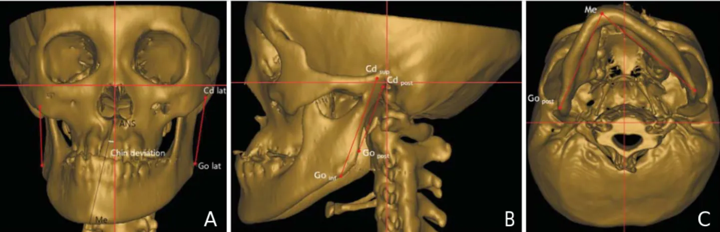
Condylar landmarks, gonial landmarks, and menton were identified. The condylar landmarks were the most superior (Cdsup), lateral (Cdlat) and posterior (Cdpost) points of the condylar head. The gonial landmarks were the most inferior (Goinf), lateral (Golat) and posterior (Gopost) points of the gonion area. Menton (Me) was the most inferior point on the mandibular symphysis. The lines, longitude of ramus (LR: Cdsup-Goinf), ramus lateral (RL: Cdlat-Golat), ramus posterior (RP: Cdpost-Gopost) and mandibular body (MB:
Gopost-Me) were established with connecting each land- mark. The rectangular coordinates (|x|, y, z) were obtained by the measurement tool. |x| was the distance from the mid- sagittal reference plane, y was the distance from coronal plane, and z was the distance from the horizontal reference
plane; |x| was set to an absolute value for our purpose of comparing differences of the deviated side and the opposite side (Table 1, Fig. 1).
Alternate spherical coordinate systems of the facial lines
An alternate spherical coordinate system was developed from the geographic coordinate system for 3D evaluation of the facial lines and facial asymmetry.15
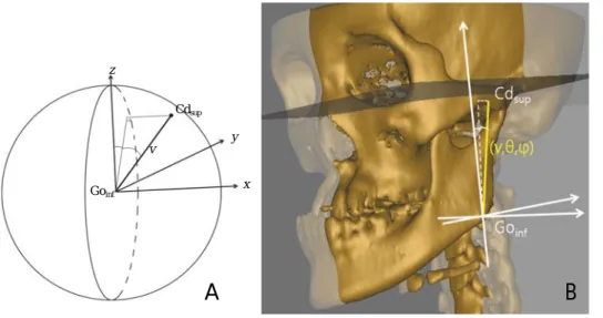
Figure 2 shows the definition of the alternate spherical
coordinate system (v, θ, ϕ) of LR as an example. The three orthogonal axes were drawn, centered at the landmark, Goinf. LR was identified as a vector and its length v was measured. The angle between the midsagittal reference plane and the vector were identified as midsagittal inclina- tion angle, θ. The angle between the coronal plane and the projection line of the vector onto the midsagittal reference plane was identified as coronal inclination angle, ϕ. The alternate spherical coordinates (v, θ, ϕ) of other facial lines were made in the same way. The line LR (Cdsup-Goinf) was formed as (xcd-xgo, ycd-ygo, zcd-zgo), where (xcd, ycd, zcd) is for
Table 1.Landmarks, planes and facial lines used for this study
Landmarks Cg Most superior point of crista galli
ANS Anterior nasal spine
Op Most posterior point on posterior margin of foramen magnum
Or Deepest point on infraortibal margin
Po Highest point on roof of external auditory meatus Dent Highest point on odontoid process of 2nd cervical vertebra Cdsup Most superior point of condyle
Cdlat Most lateral point of condyle Cdpost Most posterior point of condyle Goinf Most inferior point of gonion area Golat Most lateral point of gonion area Gopost Most posterior point of gonion area
Me Most inferior point on symphysis of mandible Planes Midsagittal plane A plane defined by Cg, ANS and Op
Horizontal plane A plane perpendicular to midsagittal plane and passing through right Or and left Po Coronal plane A plane perpendicular to midsagittal and horizontal planes and passing through Dent Facial lines LR Longitude of ramus; line connecting Cdsupand Goinf
RL Ramus lateral; line connecting Cdlatand Golat
RP Ramus posterior; Line connecting Cdpostand Gopost
MB Mandibular body; Line connecting Gopostand Me
Fig. 1.A mandibular prognathism individual. Three orthogonal planes were established, and facial lines were identified. A. The chin devia- tion was 12.95�. The ramus lateral (RL) was identified with the most lateral points of condyle and of gonoin area. B. The longitude of the ramus (LR) was identified with the most superior point of condyle and the most inferior point of gonion area, and the ramus posterior (RP) with the most posterior points of condyle and gonion area. C. The mandibular body (MB) was identified with menton and the most poste- rior point of gonion area.
A B C
Cdsupand (xgo, ygo, zgo) is for Goinf. If x==xcd-xgo, y==ycd-ygo, and z==zcd-zgo, the alternate spherical coordinates (v, θ, φ) were obtained from the formulae as below:
v== x2++y2++z2, θ==sin-1(x/v), ϕ==tan-1(y/z),
then θ, ϕ in radian measure were converted into θ, ϕ in angle (θrad==θ�×π/180; ϕrad==ϕ�×π/180).
The bilateral differences of the alternate spherical coordi- nates (dv, dθ, dϕ) between the deviated side and the oppo- site side was obtained (Fig. 2).
Because the bilateral facial lines have different starting points on the three-dimensional space, it was also necessary to describe the starting point for a definite representation of the vectors. The bilateral difference (dx, dy, dz) of the starting points, Goinf, Golat, Gopostwere obtained.
Statistical analysis
The bilateral differences of the spherical polar coordinates of each line (dv, dθ, dϕ) were compared between the groups by Mann-Whitney U test. The correlation with chin devia- tion was statistically analyzed by Spearman’s test. The bilateral differences of the landmarks (dx, dy, dz) were sta- tistically compared by Mann-Whitney U test. SPSS 18.0 (SPSS Inc, Chicago, IL, USA) was used for the statistic analysis.
Results
Bilateral difference of the alternate spherical coordinates of facial lines
The bilateral differences of lengths of LR, RL, RP and
MB were -1.62±3.61 mm, -1.13±6.29 mm, 0.06±4.04 mm and -0.83±2.38 mm in the symmetric group, and -3.45±4.59 mm, -3.12±5.23 mm, -3.26±4.53 mm and -3.15±2.92 mm in the asymmetric group; the facial lines of the deviated side were generally shorter than those of the opposite side. The bilateral differences of lengths of RL and MB were significantly different between the groups (p⁄0.05). The bilateral differences of midsagittal inclination angles of LR, RL, RP and MB were -1.41±
2.46�, -1.48±2.6�, -2.25 ±3.32�and 0.24±2.57�in the symmetric group, and -4.36±3.86�, -4.99±4.15�, -3.84±5.06� and -0.15±2.96� in the asymmetric group; the facial lines of the deviated side were generally more inclined toward the midsagittal plane than those of the opposite side. The bilateral differences of the midsagit- tal inclination angles of LR, RL, RP and MB were signifi- cantly different between the groups (p⁄0.05). The bilateral differences of coronal inclination angles of LR, RL, RP and MB were -0.42±3.29�, 1.56±10.93�, -0.23±3.98�, -1.65±1.74�in the symmetric group, and -1.28±3.78�, -2.34±11.69�, -3.49±4.03�and -8.06±3.84�in the asymmetric group. The facial lines of the deviated side were generally more inclined toward the coronal plane than those of the opposite side; however, there was no signifi- cant difference between the two groups in the bilateral dif- ferences of coronal inclination angle of the facial lines.
The differences of the length and midsagittal inclination of LR and MB were significantly correlated with chin deviation (p⁄0.05). The differences of the midsagittal in- clinations of all the lines had significant correlations with chin deviation (p⁄0.05). The difference of the midsagittal inclination of the MB had a fairly high negative correlation with chin deviation (r==-0.829, p⁄0.05). LR and RL
Fig. 2. A. An alternate spherical coordinate system (v, θ, ϕ) for 3D evaluation of the longitude of ramus (Cdsup-Goinf) as an example, where v is the length, θ the midsagittal in- clination angle, ϕ the coronal incli- nation angle. B. This picture shows the alternate spherical coordinate system of the longitude of the ramus of the patient in Figure 1.
A B
Cdsup
Goinf
y
x z
ϕ θ v
showed a relatively high negative correlation with chin deviation in the difference of midsagittal inclination (r== -.619, -.674, p⁄.05). As menton was deviated from the midsagittal reference plane, the bilateral differences of the midsagittal inclinations of LR, RL, RP and MB were neg- atively increased. The lines of the deviated side were more inclined to the midsagittal reference plane than those of the opposite side. There was no significant correlation of the coronal inclinations to the chin deviation (Table 2).
Bilateral difference of the starting points
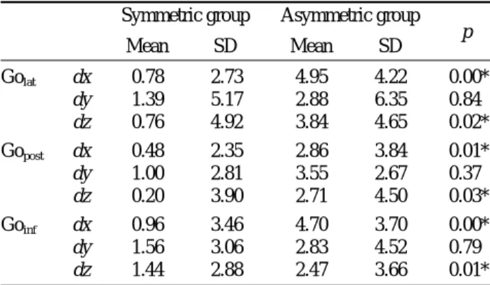
The bilateral differences dx and dz of the landmarks Goinf, Golat and Gopostwere significantly different between the two groups (p⁄0.05). The landmarks of deviated side were
significantly more laterally and superiorly to the opposite side in the asymmetric group than in the symmetric group (Table 3).
Discussion
The purpose of this study was to compare asymmetric mandibular prognathism individuals with symmetric mandi- bular prognathism individuals using a new alternate spheri- cal coordinate system.
A spherical coordinate system is a coordinate system for three-dimensional space where the position of a point is specified by three factors: radius, inclination angle, and azimuth angle.14,15The spherical coordinate system can be altered and applied for many purposes. In geography, the spherical coordinate system is altered as the geographic coordinate system. The geographical coordinate system, an alternate spherical coordinate system, uses the longitude and latitude, the inclination angle from the equatorial plane and the inclination angle from the meridian to express loca- tions on Earth. The new alternate spherical coordinate in this study was derived from the geographic coordinate sys- tem. The length of the vector was measured for each facial line, because the study objects were not spheres of unit radius. The midsagittal inclination angle was defined as the inclination angle from the midsagittal reference plane.
The coronal inclination was the inclination angle from the coronal reference plane. In this study, the new alternate spherical coordinate systems of the representing lines of the facial asymmetry were obtained, using the three factors of the lines, length, midsagittal and coronal inclination
Table 2.The bilateral differences of the spherical polar coordinates of each line (dv, dθ, dϕ) and the correlation with chin deviation according to the groups
Symmetric group Asymmetric group Correlation
Mean SD Mean SD p Coefficient (r) p
LR dv (mm) -1.62 3.61 -3.45 4.59 0.050 -0.467 0.004�
dθ (�) -1.41 2.46 -4.36 3.86 0.000* -0.619 0.000�
dϕ (�) -0.42 3.29 -1.28 3.78 0.550 -0.051 0.768
RL dv (mm) -1.13 6.29 -3.12 5.23 0.027* 0.236 0.178
dθ (�) -1.48 2.60 -4.99 4.15 0.000* -0.674 0.000�
dϕ (�) 1.56 10.93 -2.34 11.69 0.470 -0.126 0.476
RP dv (mm) 0.06 4.04 -3.26 4.53 0.973 -0.176 0.298
dθ (�) -2.25 3.32 -3.84 5.06 0.044* -0.411 0.011�
dϕ (�) -0.23 3.98 -3.49 4.03 0.198 -0.294 0.073
MB dv (mm) -0.83 2.38 -3.15 2.92 0.003* -0.577 0.000�
dθ (�) 0.24 2.57 -0.15 2.96 0.000* -0.829 0.000�
dϕ (�) -1.65 1.74 -8.06 3.84 0.118 -0.182 0.261
*p⁄0.05 statistically significant in comparing the groups by Mann-Whitney U test. �p⁄0.05 statistically significant in correlation with chin deviation by Spearman’s test. dv: bilateral difference of vector length of the facial line. dθ: bilateral difference of midsagittal inclination angle of the facial line. dϕ: bilateral difference of coronal inclination angle of the facial line
Table 3. The bilateral differences of the rectangular coordinates of each landmark (dx, dy, dz) according the groups (unit: mm)
Symmetric group Asymmetric group
Mean SD Mean SD p
Golat dx 0.78 2.73 4.95 4.22 0.00*
dy 1.39 5.17 2.88 6.35 0.84
dz 0.76 4.92 3.84 4.65 0.02*
Gopost dx 0.48 2.35 2.86 3.84 0.01*
dy 1.00 2.81 3.55 2.67 0.37
dz 0.20 3.90 2.71 4.50 0.03*
Goinf dx 0.96 3.46 4.70 3.70 0.00*
dy 1.56 3.06 2.83 4.52 0.79
dz 1.44 2.88 2.47 3.66 0.01*
*p⁄0.05 Comparison of the groups by Mann-Whitney U test and correla- tion with chin deviation by Spearman’s test
angles. The facial lines have different starting points. It was also necessary to describe the starting point for a definite position of the lines. The bilateral difference (dx, dy, dz) of the starting points of the lines should be obtained.
In the previous researches, the length and/or inclination of facial lines were evaluated, however only one or two factors of spherical coordinates of the lines were defined.9-13 The 3D characteristics of the facial lines have not been fully explained. Even if two lines share one identical factor, the lines would not be the same if the other factor is different.
For example, even if two lines are the same in length, but if the midsagittal or coronal inclination angle is different, the lines are different from each other. Therefore, the three factors of facial lines should be presented to identify the lines.
In this study, the asymmetric group was significantly dif- ferent from the symmetric group in the length of LR and MB and in the midsagittal inclination of LR, RL, RP and MB. The difference of the lengths of LR and MB had fair correlation with the chin deviation. The differences of the midsagittal inclinations of LR, RL, RP and MB had fair or high correlations with the chin deviation. The bilateral difference of the gonial landmarks was significantly differ- ent between the groups. The differences dx and dz of the starting points were statistically and significantly greater in the asymmetric group than in the symmetric group.
In this study, the facial lines evaluated by Hwang et al9 were reilluminated using spherical coordinate system. The spherical coordinate system could be applied to analyze any facial lines.
In conclusion, this study showed that the spherical coordi- nate system was useful for 3D evaluation of the facial asymmetry using the ability of the spherical coordinates to identify the 3D facial lines by its length and angle inclina- tions. The alternate spherical coordinate might be useful in the measurements of the lines of interest in orthodontic treatment. In this study, the bilateral differences of lengths of LR, RL and MB and the midsagittal inclination of LR, RL, RP and MB contributed to the facial asymmetry in mandibular prognathism individuals.
References
1. Grummons DC, Kappeyne van de Coppello MA. A frontal
asymmetry analysis. J Clin Orthod 1987; 21 : 448-65.
2. Haraguchi S, Takada K, Yasuda Y. Facial asymmetry in sub- jects with skeletal Class III deformity. Angle Orthod 2002; 72 : 28-35.
3. Ferguson JW. Cephalometric interpretation and assessment of facial asymmetry secondary to congenital torticollis. The signi- ficance of cranial base reference lines. Int J Oral Maxillofac Surg 1993; 22 : 7-10.
4. Decker JD. Asymmetric mandibular prognathism: a 30-year ret- rospective case report. Am J Orthod Dentofacial Orthop 2006;
129 : 436-43.
5. Matteson SR, Bechtold W, Phillips C, Staab EV. A method for three-dimensional image reformation for quantitative cephalo- metric analysis. J Oral Maxillofac Surg 1989; 47 : 1053-61.
6. Ono I, Ohura T, Narumi E, Kawashima K, Matsuno I, Nakamu- ra S, et al. Three-dimensional analysis of craniofacial bones using three-dimensional computer tomography. J Craniomax- illofac Surg 1992; 20 : 49-60.
7. Katsumata A, Fujishita M, Maeda M, Ariji Y, Ariji E, Langlais RP. 3D-CT evaluation of facial asymmetry. Oral Surg Oral Med Oral Pathol Oral Radiol Endod 2005; 99 : 212-20.
8. Maeda M, Katsumata A, Ariji Y, Muramatsu A, Yoshida K, Goto S, et al. 3D-CT evaluation of facial asymmetry in patients with maxillofacial deformities. Oral Surg Oral Med Oral Pathol Oral Radiol Endod 2006; 102 : 382-90.
9. Hwang HS, Hwang CH, Lee KH, Kang BC. Maxillofacial 3- dimensional image analysis for the diagnosis of facial asymme- try. Am J Orthod Dentofacial Orthop 2006; 130 : 779-85.
10. Kwon TG, Park HS, Ryoo HM, Lee SH. A comparison of cran- iofacial morphology in patients with and without facial asym- metry--a three-dimensional analysis with computed tomogra- phy. Int J Oral Maxillofac Surg 2006; 35 : 43-8.
11. Park SH, Yu HS, Kim KD, Lee KJ, Baik HS. A proposal for a new analysis of craniofacial morphology by 3-dimensional computed tomography. Am J Orthod Dentofacial Orthop 2006;
129 : 600.e23-34.
12. Baek SH, Cho IS, Chang YI, Kim MJ. Skeletodental factors affecting chin point deviation in female patients with class III malocclusion and facial asymmetry: a three-dimensional an- alysis using computed tomography. Oral Surg Oral Med Oral Pathol Oral Radiol Endod 2007; 104 : 628-39.
13. You KH, Lee KJ, Lee SH, Baik HS. Three-dimensional com- puted tomography analysis of mandibular morphology in pati- ents with facial asymmetry and mandibular prognathism. Am J Orthod Dentofacial Orthop 2010; 138 : 540.e1-e8.
14. Thomas GB, Finney RL. Calculus and analytic geometry. 5th ed. Reading : Addison-Wesley; 1982. p. 669-70.
15. Fisher NI, Lewis T, Embleton BJJ. Statistical analysis of spher- ical data. Cambridge : Cambridge University Press; 1987. p.
17-28.