원전 냉각수 취수용 GFRP 관의 장기관변형 예측
김선희
1ㆍ박준석
2ㆍ윤순종
3홍익대학교 토목공학과 박사과정1, 홍익대학교 토목공학과 연구원2, 홍익대학교 토목공학과 교수3
Long-term Ring Deflection Prediction of GFRP Pipe in Cooling Water Intake for the Nuclear Power Plant
Kim, Sun-Hee
1ㆍPark, Joon-Seok
2ㆍYoon, Soon-Jong
31Ph. D. Student, Department of Civil Engineering, Hongik University, Seoul, Korea
2Researcher (Ph.D.). Department of Civil Engineering, Hongik University, Seoul, Korea
3Professor, Department of Civil Engineering, Hongik University, Seoul, Korea
Abstract: Recently, underground pipes are utilized in various fields of applications such as sewer lines, drain lines, water mains, gas lines, telephone and electrical conduits, culverts, oil lines, etc. Most of pipes are installed for long-term purposes and they should be safely installed in consideration of installation conditions because there are unexpected various terrestrial loading conditions. In this paper, we present the result of investigation pertaining to the structural behavior of glass fiber reinforced thermosetting polymer plastic (GFRP) flexible pipes buried underground. The mechanical properties of the GFRP flexible pipes produced in the domestic manufacturer are determined and the results are reported in this paper. In addition, ring deflection is measured by the field tests and the finite element analysis (FEA) is also conducted to simulate the structural behavior of GFRP pipes buried underground. From the field test results, we predicted long-term, up to 50 years, ring deflection of GFRP pipes buried underground based on the method suggested by the existing literature. It was found that the GFRP flexible pipe to be used for cooling water intake system in the nuclear power plant is appropriate because 5% ring deflection limitation for 50 years could be satisfied.
Key Words: GFRP Pipe, Experiment, Regression Analysis, FEA, Long-term Ring Deflection
주요어: GFRP 관, 실험, 회귀분석, 유한요소해석, 장기관변형 Corresponding author: Yoon, Soon-Jong
Department of Civil Engineering, Hongik University, 72-1 Sangsu-dong, Mapo-gu, Seoul 172-732, Korea.
Tel: +82-2-3141-0774, Fax: +82-2-3141-0774, E-mail: [email protected]
투고일: 2012년 7월 10일 / 수정일: 2012년 7월 31일 / 게재확정일: 2012년 8월 9일
1. Introduction
Glass fiber reinforced thermosetting polymer plastic (GFRP) pipes are widely used in the construction industries due to the advantages of their superior mechanical and physical characteristics such as high chemical resistance, high corrosion resistance, right weight, smooth surface texture of the pipe, cost effectiveness from soil-structure interaction, etc. (Kim, 2010).
In general, pipes buried underground can be classified
into either rigid or flexible. GFRP pipe may be considered as one of typical flexible pipes for which the soil-pipe structure interaction must be taken into account in the design.
Spangler was convinced that buried corrugated steel culverts invert at the top when ring deflection is about 20% (Watkins, 2000). The ring deflection is defined as following.
∆
×
(1)
In Eq. (1), is the pipe diameter and ∆ is the amount of vertical deflection measured from the original position. So, Spangler applied a safety factor of four and proposed that buried pipe be limited to 5%
ring deflection (Watkins, 2000).
In this paper, we estimated the long-term ring deflection by the method of regression analysis on the GFRP buried pipe based on the data obtained by the field tests and the material tests conducted in the laboratory. In the prediction, we used the method suggested by the KS M ISO 10928 (2004).
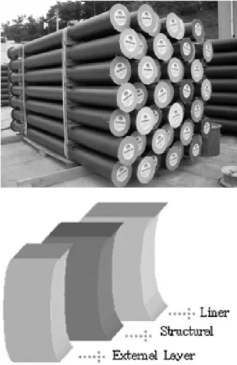
GFRP pipe was produced by Gilgwang Greentech Co., Ltd. Actual dimension of the pipe to be used for the intake of cooling water in the nuclear power plant under construction was determined by the company. The cross-section of GFRP pipe consists of three layers such as liner layer, structural layer, and external layer as shown in Fig. 1.
Fig. 1 GFRP Pipe and Section Composition (Research Report, 2011)
2. Experimental Study
2.1 Structural Behavior
GFRP flexible pipes used in the test are products manufactured by the filament winding technique in the Gilgwang Greentech Co., Ltd. in Korea. Three parallel plate loading test specimens are taken in the transverse direction of the pipe according to the KS M ISO 10466. Dimension of GFRP pipe specimen for the parallel plate loading test is shown in Table 1.
Table 1. Specimen Designation and Dimension of the Parallel Plate Loading Test (KS M ISO 9969)
Specimen designation
Dimension Length
(L, mm)
Diameter (D, mm)
Thickness (t, mm) GFRP-1
300 1,500 21
GFRP-2 GFRP-3
A 30cm length and 150cm diameter pipe specimen is loaded up to failure with a constant loading speed of 50 mm/min at a constant room temperature of 23℃.
The typical parallel plate loading test set-ups and testing of GFRP pipe are shown in Fig. 2.
Fig. 2 Parallel Plate Loading Test Set-up (KS M ISO 9969)
The pipe stiffness (PS) and the load at 5% ring deflection are summarized as given in Table 2.
Specimen designation
At 5% ring deflection At failure Load
(kN/m)
PS (kN/m2)
Load (kN/m)
Deflection (%) G-1 21.74 285.65 1,765.88 44.20 G-2 22.62 297.25 1,210.48 28.10 G-3 21.54 283.07 1,208.33 29.80 Average 21.97 288.66 1,394.90 34.03 Table 2. Result of the Parallel Plate Loading Test of GFRP
pipes (Research Report, 2011)
3. Field Test
GFRP flexible pipes are buried underground with different overburden depths, soil compaction density, and elapsed time, as a test variable.
Test result is the vertical ring deflection which is defined as the vertical contraction of pipe diameter after deformation divided by the original pipe diameter (∆ ). In the test, dead load and live load effects on the structural behavior of buried pipes are investigated, respectively or in combination. In the field tests, GFRP pipes having 2,400mm diameter are installed and compaction of backfill material with 95% standard proctor compaction density was conducted. From bedding to haunch of the pipe the backfill material is compacted using vibrating roller and the backfill soil is compacted by 30cm, layer by layer, intervals using roller above the pipe haunch.
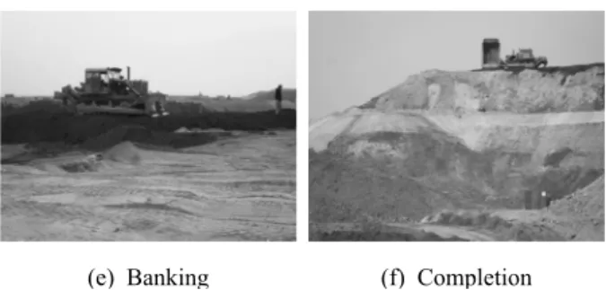
Fig. 3 shows GFRP pipe installation and compaction of backfill material. (Research Report, 2011)
(a) Delivery (b) Connection
(c) Installation (d) Compaction
(e) Banking (f) Completion Fig. 3 Installation and Compaction of GFRP Pipe (Research
Report, 2011)
In the deflection measurement of the GFRP flexible pipes buried underground, 1/1000 mm measurement accuracy dial gages are used. The location of deflection measurement is at the center of pipe, connection of pipe, and 1.5m distance from the connection of pipe.
Fig. 4 shows schematically the location of deflection measurement.
Fig. 4 Location of Measurement (Research Report, 2011)
(a) Vertical ring deflection (%)
(b) Horizontal ring deflection (%)
Fig. 5 Result of Ring Deflection (Research Report, 2011)
Measuring points, No. 3 and No. 4, are located at the center of pipe and points, No. 1 and No. 2, are located at the point of connection of pipe segment. In addition, strain gages (indicated by Ch. 1 to Ch. 6) are also attached on the inside surface of GFRP pipe to observe long-term variation of strain of the pipe (refer to Fig. 4) (Research Report, 2011).
GFRP pipes are buried underground with 95%
standard proctor density of backfill material, the pipe ring deflection measured until 218 days.
Results show that the vertical ring deflection by percent is in the range of 2.37% to 4.00%. In addition, the horizontal ring deflection by percent is also in the range of 2.24% to 2.72%. Therefore, it was found that the ring deflection is far less than 5% limitation specified in the Guideline of Sewer System (Ministry of Environment, Korea) and Fiberglass Pipe Design Manual M 45 (American Water Works Association, AWWA).
Vertical and horizontal ring deflections measured at the center of the pipe are the largest. The deflections measured at the point of connection of pipes are the smallest. Because, at the point of pipe connection, the thickness of both pipes at the point (No. 1 and No.
2) (refer to Fig. 4) of connection is increased by hand lay-up of glass fiber and polyester resin (i.e., the thickness of pipe affects significantly to the pipe stiffness).
4. Analytical Study
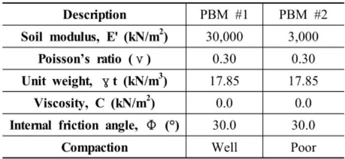
Structural behavior of all three GFRP flexible pipes buried underground is investigated by the finite element analysis, MIDAS/GTS, which is a general purpose geotechnical analysis program. In the finite element analysis modeling, ground conditions, mechanical properties of material, and loading conditions are considered in the finite element simulation. The pipe bedding and backfill material (PBM) characteristics are summerized in Table 3 based on the result of field tests. The mechanical properties of the flexible pipe material used in the modeling and analysis of the finite element analysis are considered to be isotropic material based upon the test results in which the material properties are selected conservatively as given in Table 4.
Description PBM #1 PBM #2
Soil modulus, E' (kN/m2) 30,000 3,000
Poisson’s ratio (ν) 0.30 0.30
Unit weight, γt (kN/m3) 17.85 17.85 Viscosity, C (kN/m2) 0.0 0.0 Internal friction angle, Φ (°) 30.0 30.0
Compaction Well Poor
Table 3. Pipe Bedding and Backfill Material (PBM) Characteristics (Research Report, 2011)
DescriptionModulus of elasticity E (GPa)
Poisson’s ratio ν
Thickness t (mm)
GFRP pipe 24.56 0.23 35
Table 4. Mechanical Properties of GFRP Pipe (Research Report, 2011)
In the finite element analysis, three different cases are considered based on the different bedding and backfill soil conditions and the range of domain around the GFRP pipes buried underground. The details are described in Table 5.
Description Soil condition around GFRP pipe Domain Soil characteristic Case 1 Whole of soil around
GFRP pipe
Pipe bedding material
#1 Case 2 Center of GFRP pipe
(2×D)
Pipe bedding material
#2 Case 3 Center of GFRP pipe
(3×D)
Pipe bedding material
#2
Table 5. Soil Conditions around the GFRP Pipe (Research Report, 2011)
As shown in Figs. 6 and 7, the GFRP pipe is modeled by considering actual thickness and dimension of the GFRP pipe.
Fig. 6 Grid Mesh (Research Report, 2011)
Fig. 7 Finite Element Model of GFRP Pipe (Shell Element) (Research Report, 2011)
One of typical deflected shapes under different backfill soil depths of the GFRP pipe obtained by the finite element analysis is shown in Fig. 8.
(a) Vertical deflection (5m) (d) Horizontal deflection (5m)
(b) Vertical deflection (10m) (e) Horizontal deflection (10m)
(c) Vertical deflection (16m) (f) Horizontal deflection (16m) Fig. 8 Result of Ring Deflection (Research Report, 2011)
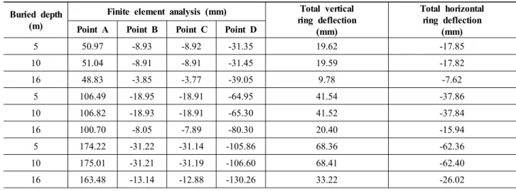
Detailed results of ring deflection at each case are given in Table 6.
Buried depth (m)
Finite element analysis (mm) Total vertical ring deflection
(mm)
Total horizontal ring deflection Point A Point B Point C Point D (mm)
5 50.97 -8.93 -8.92 -31.35 19.62 -17.85
10 51.04 -8.91 -8.91 -31.45 19.59 -17.82
16 48.83 -3.85 -3.77 -39.05 9.78 -7.62
5 106.49 -18.95 -18.91 -64.95 41.54 -37.86
10 106.82 -18.93 -18.91 -65.30 41.52 -37.84
16 100.70 -8.05 -7.89 -80.30 20.40 -15.94
5 174.22 -31.22 -31.14 -105.86 68.36 -62.36
10 175.01 -31.21 -31.19 -106.60 68.41 -62.40
16 163.48 -13.14 -12.88 -130.26 33.22 -26.02
* Location of measuring point
Table 6. Results of Analytical Study (Research Report, 2011)
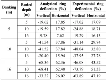
As mentioned above, test results and analytical results are compared as shown in Table 7.
Banking (m)
Buried depth
(m)
Analytical ring deflection (%)
Experimental ring deflection (%) Vertical Horizontal Vertical Horizontal 5
5 -19.62 17.85 -17.02 17.09 10 -19.59 17.82 -24.88 18.71 16 -9.78 7.62 -19.29 16.13
10
5 -41.54 37.86 -31.14 29.74 10 -41.52 37.84 -48.04 32.80 16 -20.40 15.94 -37.95 27.78
16
5 -68.36 62.36 -46.08 43.52 10 -68.41 62.40 -73.79 51.33 16 -33.22 26.02 -63.89 47.19 (+): increase of diameter, (-): decrease of diameter Table 7. Comparison of Results (Research Report, 2011)
5. Prediction of Long-Term Ring Deflection
The method for the prediction of long-term ring deflection have been developed and suggested by ASTM D 5365 which was adopted in KS M ISO 10928 (2004). In the method, strain (and/or deflection) measured with elapsed time is used for the ring deflection prediction. Testing was conducted following the guidelines of KS M ISO 10928-04 (Plastic piping systems-Glass-reinforced thermosetting plastics (GRP) pipes and fittings-Methods for regression analysis and their use).
KS M ISO 10928 (2004) suggests the method to predict long-term ring bending strain of GFRP pipe.
By following the method suggested by KS M ISO 10928 (2004), the regression equation is:
log log (1)
In Eq. (1), and are the parameters relating to ring bending strain, is the elapsed time (in hour).
The parameters and are as follows:
× (2)
(3)
In Eqs. (2) and (3), is the arithmetic mean of all ring strain values, is the arithmetic mean of all
the time to failure in hours of observation, is the slope of the load versus strain curve, respectively.
From Eq. (1), following form of equation can be derived.
× log(4)
As shown in Table 8 and shown in Fig. 9, result of predicted long-term ring bending strain is presented.
Period of time (Year)
log (%) strain
Vertical Horizontal No. 1 No. 3 No. 5 No. 2 No. 4 No. 6 10 1.82 2.93 2.55 1.74 2.05 1.89 20 1.77 2.84 2.47 1.69 2.00 1.83 30 1.76 2.80 2.43 1.67 1.96 1.80 40 1.72 2.76 2.40 1.65 1.94 1.77 50 1.71 2.74 2.38 1.64 1.92 1.75 Table 8. Predicted Result of Long-term Ring Bending Strain
The test data was analyzed by log-log linear least squares regression to find the 50-year expected strain.
Fig. 9 Prediction of Long-term Ring Strain
Since the 5% limitation of the long-term ring deflection is specified in the design specification we need to predict the ring deflection as follows.
× log(5)
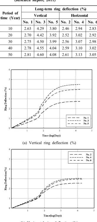
Strain is related to deflection. In Table 9, result of predicted long-term ring deflection is presented. It can be seen in Table 9 the long-term ring deflection is less than 5% ring deflection limitation suggested by the relevant specification or guideline. Fig. 10 shows the long-term ring deflection up to 50 years (i.e., 4 indicated 10,000days).
Period of time (Year)
Long-term ring deflection (%)
Vertical Horizontal
No. 1 No. 3 No. 5 No. 2 No. 4 No. 6 10 2.63 4.29 3.80 2.46 2.94 2.83 20 2.70 4.42 3.92 2.52 3.02 2.92 30 2.75 4.50 3.99 2.56 3.07 2.98 40 2.78 4.55 4.04 2.59 3.10 3.02 50 2.81 4.60 4.08 2.61 3.13 3.05 Table 9. Predicted Result of the Long-term Ring Deflection
(Research Report, 2011)
(a) Vertical ring deflection (%)
(b) Horizontal ring deflection (%)
Fig. 10 Prediction of Long-term Ring Deflection (Research Report, 2011)
6. Conclusion
In this paper, the pipe ring deflection is measured at the field on the GFRP pipe buried underground. In addition, using MIDAS/GTS the finite element analysis is also performed with various parameters such as soil compaction density of bedding, backfill materials, and different buried depths. Both analytical and experimental results are compared and discussed.
The long-term ring deflection (up to 50 years) is also predicted based on the method suggested by the KS M ISO 10928 (2004). It was found that the ring deflection, up tp 50 years, of GFRP pipe buried underground is within the 5% ring deflection limitation.
Acknowledgement
This research had been conducted under the financial support provided by Gilgwang Greentech Co., Ltd.
References
ASTM D 5365. (2006). “Standard test method for long-term ring-bending strain of fiberglass (glass-fiber-reinforced thermosetting-resin) pipe.” American Society for Testing and Materials.
AWWA. (2005). “Fiberglass pipe design.” 2nd Ed. Manual No. M 45, American Water Works Association.
Hongik University Research Institute of Science and Technology. (2011). “Investigation of pipe deflection behavior and prediction of long-term ring deflection of GFRP pipe (φ2,400mm) buried underground.”
Research Report. Seoul, Korea.
KS M ISO 9969. (2008). “Thermoplastics pipes-determination of ring stiffness” Korean Agency for Technology and Standards (KS), Seoul, Korea.
KS M ISO 10928. (2004). Plastics piping systems-glass-reinforced thermosetting plastics (GRP) pipes and fittings-methods for regression analysis and their use, Korean Agency for Technology and Standards (KS), Seoul, Korea.
Kim, S. H., Choi, J. W., Joo, H. J., and Yoon, S. J.
(2010). “Estimation of load carrying capacity of pultruded FRP compression member.” The Korean Society for Composite Materials.
Kim, S. H., Ok, D. M., An, D. J., Hong, W. H., and Yoon, S.-J. (2012). “Prediction of long-term ring deflection of buried GFRP flexible pipe.” The 2nd International Conference on Advanced Polymer Matrix
Composites.
MIDAS/GTS. (2009). Analysis reference, MIDAS Information Technology Co., Ltd.
Park J. S. (2012). A Study on the ring deflection limitation of buried flexible pipes. Ph.D. Thesis, Department of Civil Engineering, Hongik University, Seoul, Korea.
Watkins, R. and Anderson, L. R. (2000). Structural Mechanics of Buried Pipes. CRC Press, New York.