Fabrication of Fe-TiB
2Composite Powder by High-Energy Milling and Subsequent Reaction Synthesis
H. X. Khoa, N. Q. Tuan, Y. H. Lee, B. H. Lee, N. H. Vieta, and J. S. Kim*
School of Materials Science and Engineering, University of Ulsan, San-29, Mugeo-2 Dong, Nam-Gu, Ulsan, 680-749, Korea
aSchool of Materials Science and Engineering, Hanoi University of Science and Technology, No 1, Dai Co Viet Street, Hai Ba Trung dist, Hanoi, Vietnam
(Received June 11, 2013; Accepted June 24, 2013)
···
Abstract TiB2-reinforced iron matrix composite (Fe-TiB2) powder was in-situ fabricated from titanium hydride (TiH2) and iron boride (FeB) powders by the mechanical activation and a subsequent reaction. Phase formation of the composite powder was identified by X-ray diffraction (XRD). The morphology and phase composition were observed and measured by field emission-scanning electron microscopy (FE-SEM) and energy-dispersive X-ray spectroscopy (EDS), respectively. The results showed that TiB2 particles formed in nanoscale were uniformly distributed in Fe matrix.
Fe2B phase existed due to an incomplete reaction of Ti and FeB. Effect of milling process and synthesis temperature on the formation of composite were discussed.
Keywords: Fe-TiB2 composite, Mechanical activation, Solid state reaction, Heat treatment
···
1. Introduction
Fe-based metal matrix composites have found many applications in tools, dies and wear-resistant parts for last several decades. Adding refractory particles to the Fe matrix as dispersoid improves mechanical properties of the matrix and increases wear property [1-2]. Among various ceramic particulates, TiB2 is considered to be one of the best reinforcements for steel matrix due to its high melting point (2980°C), high hardness (3400 kg/mm2, only lower than diamond, BN and B4C), high elastic modulus, good corrosion resistance and chemical inert- ness. In terms of thermal and electrical conductivities, TiB2 is favoured in selection because of its high thermal (60-120 W/mK) and electrical (~105 S/cm) conductivi- ties.
One of the most common techniques of producing these types of particulate-reinforced metal-matrix com- posites is powder metallurgy. An important factor influ- encing the structure and properties of the composites is the ceramic metal interface [2]. Recently, in situ tech-
nique has been developed to incorporate ceramic par- ticulates into metal matrices. The major advantage of in situ process is that the dispersed ceramic phase is cre- ated by the chemical reaction between elements of their compounds so that the particles are formed within the metal matrix and are clean, non-oxidized particle-matrix interfaces with higher interfacial strength, improved wet- tability and better particle-size distribution [3]. The syn- thesis of TiB2 phase by various methods have been given: laser cladding [4-5], plasma transferred arc (PTA) [6], aluminothermic reduction [7], and self-propagating high temperature synthesis (SHS) [2, 8]. They indicate that TiB2 particles are able to form in situ via different routes from various initial materials. Some of them used pure elements as starting materials which is costly unfa- vourable. Most of them exhibited large TiB2 particle size.
The present work aimed at investigating the feasibility of fabricating TiB2-reinforced Fe matrix composite pow- der by a combination of mechanical activation and heat treatment. It is expected that the route is able to provide a novel process for rapid, simple and cost-effective synthe-
*Corresponding Author : Ji Soon Kim, TEL: +82-52-259-2244, FAX: +82-52-259-1688, E-mail: [email protected]
<PM리뷰>
sis method, because of its effective dispersion of the fine reinforcing particles, for Fe-TiB2 composite using tita- nium hydride (TiH2) and ferro-boron (FeB) as initial materials. Effect of milling process and heat treatment on the phase formation of composite powder was included in this study.
2. Experimental
Commercial ferro-boron alloy, FeB, and titanium hydride, TiH2, powders were used as starting materials. The TiH2 and FeB powder mixture was accurately weighed in the ratio of 27.2 wt% TiH2 and 72.8 wt% FeB to give a Fe- 38.4wt% TiB2 composite powder corresponding to the following reaction equation:
2FeB(s) + TiH2(s) → 2Fe(s) + TiB2(s) + H2(g)↑ (1) FeB in a form of lump was manually crushed and screened to remove the large fragment of FeB. The pow- der mixtures were prepared either by turbular mixing for 2h or by high-energy milling for 2 h in a high-energy ball mill (AGO-2, [9]). Stainless steel vials and balls (5 mm in diameter) were used. The balls-to-powder weight ratio was 20:1. The vials were evacuated and filled with 0.3 MPa pure argon gas before each run to prevent oxida- tion during processing. The rotational velocity of mill axis was 500 rpm.
To fabricate Fe-TiB2 composite powders, the reaction of TiH2 and FeB was carried out in a tube furnace at 1200oC in flowing Ar gas with heating rate of 5oC/min and holding time of 1 and 5 hours.
Particle size was measured using laser scattering parti- cle size analyser, Mastersizer 2000 (Malvern). Phase for-
mation of powder was identified by X-ray diffractometer using Cu Kα radiation. The microstructure and chemical elements of the composite powders were observed and analyzed by field emission scanning electron microscope (FE-SEM) equipped with energy dispersive spectroscopy (EDS).
3. Results and Discussion
3.1. Powder characteristics
The morphology of the starting powders is shown in Fig. 1. Table 1 shows a summary of the particle size analysis. The mean particle size (D50) of TiH2 and FeB are 12.5 and 7.0 µm, respectively.
Fig. 3 shows morphology of the FeB-TiH2 powder mixture after high-energy milling (a-b) and its cross-sec- tion(c). TiH2 and FeB are brittle materials, so these pow- ders get fractured easily during milling and their particle size is reduced significantly. Particle size analysis in the D10 and D50 terms are 1.2 and 3.0 µm respectively. These values prove that the FeB and TiH2 powder became finer after 2h of high-energy milling in comparison with the starting powders. But the D90 value increased after mill- ing process (D90 = 23.5 µm) by formation of agglomer- ates as shown in Fig. 3(a). The image taken on the surface of agglomerate (Fig. 3(b)) shows fine and rounded particles of
Fig. 1. FE-SEM images of starting powders; (a) TiH2 and (b) FeB powder.
Table 1. Result of particle size analysis of starting powders (volume distribution)
Powder D10
(µm) D50
(µm) D90
(µm)
Specific Area (m2/g)
TiH2 3.3 12.5 38.6 0.80
FeB 3.1 7.0 16.8 1.05
FeB and TiH2. To observe the agglomerates more clearly, the cross-section of agglomerate was investigated (Fig.
3(c)). Agglomerates formed a dense structure; the TiH2 (dark phase) homogeneously distributed around the FeB particles. TiH2 is brittle and can be milled to nanoscale by high-energy milling for short periods of time [10].
The more brittle component TiH2 gets more easily frag- mented and embedded around the less brittle component FeB. After 2h high-energy milling, the FeB particle size
decreased and distributed in a broad range from nanome- ter to several micrometer.
EDS line scan (Fig. 3(d)) on the particle outlines showed the distribution of Fe, Ti and B. The gradual change of Fe and Ti indicates the close contact between FeB and TiH2.
3.2. Thermal activation of powder mixtures
Fig. 4 shows DSC curve obtained under a constant heating rate of 10 Kmin−1 for the FeB-TiH2 powder mix- ture prepared by turbular mixing and high-energy mill- ing, respectively. DSC curve for tubular mixing shows two thermal events represented by the first two peaks at 470°C and 520°C assigning for endothermic nature of the dehydrogenation process of TiH2 compound [10], while the only a peak appeared at 370°C for the high-energy milling powder mixture. The shift to lower temperature for dehydrogenation events can be explained by effect of milling that decreases particle size [10]. At higher tem- perature, beginning at 1030°C for turbular mixing and 910°C for high-energy milling powder mixtures, respec- Fig. 2. XRD pattern of the FeB-TiH2 powder mixture prepared
by high-energy milling.
Fig. 3. (a) Fe-SEM image of FeB-TiH2 powder mixture after high-energy milling for 2h at 500 rpm, (b) the selected area with high magnification, (c) the polished cross-section, and (d) the result of EDS line scan across the particle in (c).
tively, the DSC curves shifted up signaling for appearing of thermal events. These events can be chemical solid reaction between Ti formed from the dehydrogenation process of TiH2 with boron in FeB to form TiB2 phase.
3.3. Phase composition and microstructure of FeB- TiH2 powder mixture after heat treatment
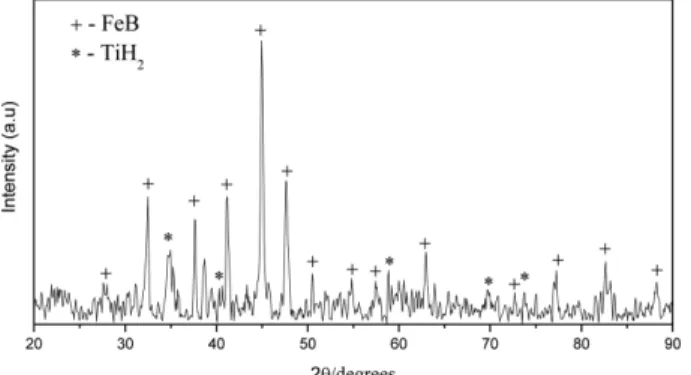
Fig. 5 shows the XRD patterns of the Fe-TiB2 composite powders by in situ synthesis from FeB-TiH2 powder mix- ture. The identified peaks are assigned to Fe, Fe2B and TiB2, respectively. There is a clear split of the peak around 45 when increasing temperature of 1100°C to 1200°C.
The possible solid state reactions involved in synthesiz- ing Fe-TiB2 composite powder has been considered. The reactions leading to formation of Fe-TiB2 composite can be suggested as follows [11-14]:
TiH2→ Ti + H2↑ (2)
Ti + 4FeB → TiB2 + 2Fe2B (3)
Ti + 2Fe2B → TiB2 + 4Fe (4)
The overall reaction of these is reaction (1) presented above. FeB phase was not found but Fe2B phase exists within the resolution of the XRD pattern. This means the reaction (4) was not completely finished, the remained Fe2B phase was also reported in [4-7]. During the pro- cess, TiH2 and FeB might interact to form some possible compounds such as TiB2, TiB or Fe2B, etc. The Gibbs free energies of formation for these compounds are [2, 14]:
Ti + 2B → TiB2 ∆G1300K = -275.5 kJ.mol−1 (6) 2Fe + B → Fe2B ∆G1300K = -67.2 kJ.mol−1 (7) Ti + B → TiB ∆G1300K = -155.3 kJ.mol−1 (8) Fe + Ti → FeTi ∆G1450K = -31.0 kJ.mol−1 (9) Fig. 4. DSC curves of FeB-TiH2 powder mixture after (a) 2h
turbular mixing and (b) high-energy milling at 500 rpm for 2h (b).
Fig. 5. XRD patterns of high-energy milled powder mixture after synthesis reaction at given conditions of temperature and time.
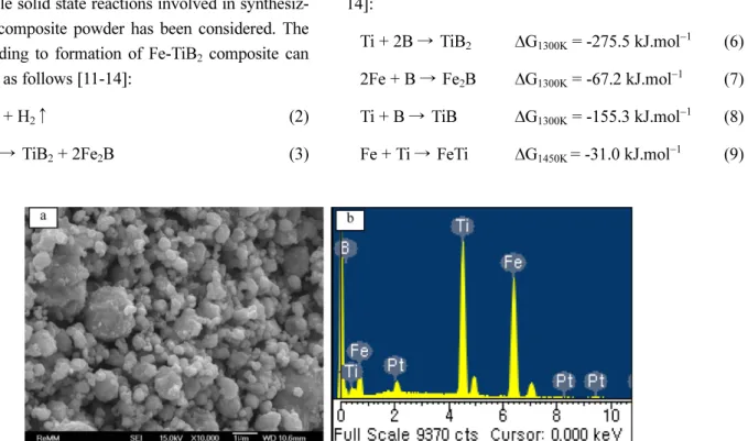
Fig. 6. FE-SEM image shows (a) morphology and (b) EDS result of Fe-TiB2 composite powder after reaction synthesis at 1200oC for 5 hour.
These value indicates that TiB2 is thermodynamically most favourable and the most stable phase. The reason for the formation of Fe2B can be explained by reaction (3), when B in FeB particles reacts with Ti on surface to form TiB2, and B content in FeB particle was depleted causing the transform of FeB to Fe2B by the newly pure Fe on surface.
The morphology of Fe-TiB2 composite powder after heat treatment at 1200oC for 5 hour is given in Fig. 6. It is hardly to identify TiB2 particle on the surfaces but Fe, Ti and B peaks appearing in EDS spectra implies that the ultrafine TiB2 particles in the Fe matrix.
Alternatively, TiB2 particles can be identified using etching step to remove Fe matrix and to leave TiB2 nano- particles on the surface (Fig. 7(a)). The nanoscale TiB2
particles form networks surrounding on the surface as shown in Fig. 7(b).
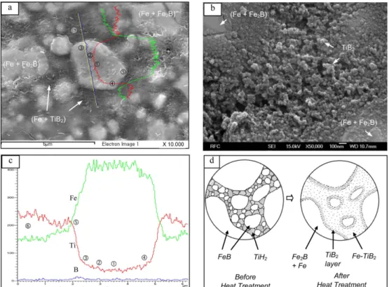
Fig. 8 shows cross-section images of powder particles after heat treatment and describes the evolution of com- posites microstructure after thermal reaction. Microstruc- ture is composed of round-bright phase embedded in the dark phase (Fig. 8(a)). Comparing Fig. 8(a) with Fig.
3(c), it can be seen that the fine FeB particles in Fig.
3(c), particle size below 1mm, were disappeared in
Fig. 7. FE-SEM image of Fe-TiB2 composite powder after etching: (a) Low and (b) high magnification.
Fig. 8. FE-SEM image of microscopic cross-section of Fe-TiB2 composite powder after (a) polishing and (b) etching. (c) Result of EDS line scan across the area marked in (a). In (d) the formation of microstructure is given schematically.
microstructure of Fig. 8(a). It means that the fine FeB particles completely reacted with Ti to form TiB2 parti- cles in Fe matrix. Fig. 8(b) shows the dark phase surface after etching, which is composed of Fe and TiB2. It is noteworthy that the TiB2 particle is extremely fine, around 50 nm, in comparison with previous results reported by others. The received TiB2 particle size was very coarse from several to tens micrometer [2, 4-8]. With coarse FeB particles, TiB2 was formed firstly on the surface, gradually created network of TiB2 particles surrounding Fe2B core (Fig. 8(d)). This formation might prevent the further diffu- sion of boron to the matrix boundary and remained a large amount of Fe2B in the powder after heat treatment.
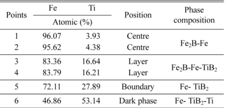
Fig. 8(c) is result from EDS line scanning of bright phase on the Fig. 8(a), showing distribution of Fe, Ti and B. Fig. 8(d) shows the schematic figure on mechanism of phase formation after heat treatment. The concentration of Ti and B are higher at boundary (Point ⑤ in Fig. 8(c)) due to TiB2 layer as mentioned above (Fig. 8(d)). The bright phase has Fe concentration much higher than that the dark phase, while Ti distribution is higher in the dark phase, as presented in the Table 2.
Table 2 shows composition of selected points analysed on microscopic cross-section surface of the composite.
Most of Ti was concentrated in the dark phase, it is clearly that the dark phase is almost the Fe-TiB2 compos- ite, in which a small amount of Ti can be included that is hardly to detect within the resolution of X-ray diffrac- tion. The bright phase was assigned for Fe2B-Fe due to the highest Fe concentration in this phase.
4. Conclusions
Fe-TiB2 composite powder was in situ synthesized
from FeB and TiH2 precursors by using high-energy mechanical milling and subsequent heat treatment proc- ess.
1) The FeB-TiH2 powder mixture after mechanical milling is fine with agglomerates. The agglomerate was composed of fine TiH2 embedded around FeB particles.
The process did not generate new phases, but lowered temperature of TiH2 dehydrogenation events.
2) DSC analysis confirms that TiH2 dehydrogenation occurs above 500ºC for starting powder and 370ºC for milled powder mixtures, while TiB2 formation is at higher temperature, above 910ºC.
3) A large amount of Fe2B phase exists in final prod- uct after heat treatment. The TiB2 particles create net- work surrounding the surface of coarse Fe-Fe2B particles.
Microstructure of the composite is characterized by the Fe-TiB2 that was formed from fine FeB particles, embed- ded around the Fe-Fe2B. Nanoscale TiB2 particles were uniformly distributed in the Fe matrix with particle size around 50 nm.
Acknowledgements
This work was supported by the 2008 Research Fund of the University of Ulsan (2008-0116).
References
[1] H. O. Pierson: Handbook of Refractory Carbides and Nitrides, William Andrew Publishing/Noyes, 1996.
[2] C. C. Degnan and P. H. Shipway: Metall. Mater. Trans. A, 33 (2002) 2973.
[3] R. M. Aikin, Jr.: JOM, 49(8) (1997) 35.
[4] B. S. Du, Z. D. Zou, X. H. Wang and S. Y. Qu: Mater. Lett., 62 (2008) 689.
[5] B. S. Du, Z. D. Zou, X. H. Wang and S. Y. Qu: Appl. Surf.
Sci., 254 (2008) 6489 .
[6] M. Darabara, G. D. Papadimitriou and L. Bourithis: Surf.
Coat. Technol., 201 (2006) 3518.
[7] Animesh Anal, T. K. Bandyopadhyay and K. Das: J.
Mater. Process. Technol., 172 (2006) 70.
[8] O. K. Lepakova, L. G. Raskolenko and Y. M. Maksimov:
Combust. Explos., 36(5) (2000) 575.
[9] E. G. Avvakumov, A. R. Potkin and O. I. Samarin: Plane- tary mill. Author’s certificate No. 975068, USSR, Patent Bulletin, No. 43 (1982).
[10] V. Bhosle, E.G. Baburaj, M. Miranova and K. Salama:
Mater. Sci. Eng. A, 356 (2003) 190.
[11] NIST-JANAF Thermochemical Tables Fourth Edition Table 2. Result of EDS composition analysis on cross-section
surface marked in Fig. 8(a)
Points Fe Ti
Position Phase composition Atomic (%)
1 96.07 3.93 Centre
Fe2B-Fe
2 95.62 4.38 Centre
3 83.36 16.64 Layer
Fe2B-Fe-TiB2
4 83.79 16.21 Layer
5 72.11 27.89 Boundary Fe- TiB2
6 46.86 53.14 Dark phase Fe- TiB2-Ti
Part I, Al-Co, W.C. Malcolm, Jr.(Ed.), American Institute of Physics, (1998) 276.
[12] ibid, (1998) 539.
[13] ibid, (1998) 1341.
[14] J. C. Gachon, M. Notin and J. Hertz: Thermochim. Acta., 48 (1981) 155.