서론 I.
.
.
(landmark) .
.
,
. ,
. ,
.
.
, . ,
. [1]
. ,
* (Corresponding Author)
: 2010. 6. 8., : 2010. 7. 16., : 2010. 8. 3.
, , :
([email protected]/[email protected]/[email protected]) : ([email protected])
, .
[2-5]
,
.
( ) [6-9]
[10,11] .
( , )
(complementary filter)
. AVR ATmega128
, .
엔코더 자이로 특성
II. /
.
. 엔코더 특성
1.
.
, .
Complementary Filtering for the Self-Localization of Indoor Autonomous Mobile Robots
, , *,
(Jae Won Han1, Jong Hyon Hwang1, Sung Kyoung Hong1, and Young-sun Ryuh2)
1Sejong Univ.
2Korea Institute of Industrial Technology
Abstract: This paper present an effective complementary filtering method using encoder and gyro sensors for the self-localization(including heading and velocity) of indoor mobile robot. The main idea of the proposed approach is to find the pros and cons of each sensor through a various maneuvering tests and to design of an adaptive complementary filter that works for the entire maneuvering phases. The proposed method is applied to an indoor mobile robot and the performances are verified through extensive experiments.
Keywords: self-localization, encoder, gyro, sensor fusion, complementary filter, indoor mobile robots
Copyright© ICROS 2010
. . 구조적 오차
1.1
∙
(misalignment)
∙
∙
비구조적 오차 1.2
( )
∙
∙
,
, .
,
. 1 .
자이로 특성 2.
, (yaw)
,
. ,
,
.
(1)
S (scale factor) , M (cross
coupling) , (fixed bias), n
.
(1) (S) ()
/
, 1 (
) .
[1-3] ,
.
(n) ,
.
MEMS 2 .
주행로봇의 위치추정 방법 III.
. 1
. X1-Y1
X2-Y2 .
.
(2)
, ,
,
. (2) .
(3)
(4)
. (3) (4)
, .
(5)
(6)
T .
, (3)-(6)
1. .
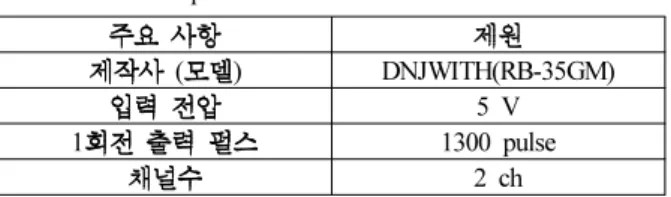
Table 1. Encoder specification.
( ) DNJWITH(RB-35GM)
5 V
1 1300 pulse
2 ch
2. .
Table 2. Gyro specification.
( ) Silicon Sensing (CRS03-02) Angular Rate Range ±100 [°/s]
Scale Factor ±0.5 %
Bias 66 [°/h]
1. .
Fig. 1. Coordinate system for mobile robot.
,
. ()
,
(7)
(8)
() .
(9)
b ,
.
( / )
. 2
3m .
( (8)) (
(9))
. , 3
1m
, 720 .
.
,
, . 보상필터 설계
IV.
III ,
. , ( / /
) (cutoff
frequency) (complementary filter) ,
. 4
.
(), () ()
() () .
5
2. .
Fig. 2. Test results for straight maneuvering.
3. .
Fig. 3. The result of curving maneuvering.
4. .
Fig. 4. Conceptual block diagram of localization algorithm.
5. - .
Fig. 5. Complementary filter for gyro-encoder fusion.
. ()
()
()
() .
( (1) )
. 6
. 5 .
(10)
(n) .
(11)
,
, . (11)
,
(12)
, 2 2
(), () , .
0.707 .
(13) ()
. , ,
.
/
.
(threshold) ,
3 .
실험 V.
하드웨어 구성 1.
4
. 7 4
, . 2
.
II 1 2 .
(MCU) ATmega128
, 100Hz
,
, , RF-
Modem .
/
MCU 7
, 8 .
6. .
Fig. 6. Response of frequency domain.
3. .
Table 3. Design parameter for each maneuvering phase.
/
Threshold (deg/s) <10 ≥10
Cutoff Frequency (rad/s) 10 0.1
Filter Gain =14.14
=100
=0.1414
=0.01
4. .
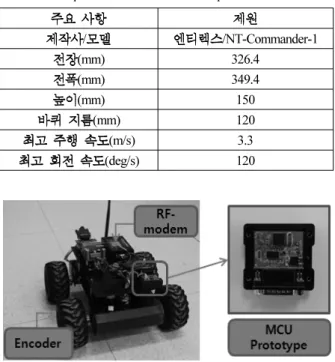
Table 4. The specification of Mobile robot platform.
/ /NT-Commander-1
(mm) 326.4
(mm) 349.4
(mm) 150
(mm) 120
(m/s) 3.3
(deg/s) 120
7. MCU .
Fig. 7. Mobile robot platform and MCU module prototype.
8. .
Fig. 8. Block diagram of test equipment configuration.
주행실험 2.
3m
/ .
9
, 10 9 5~22
. 9 10
,
.
.
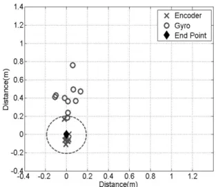
11 . ,
2~5
. 5 .
12
9. ( ).
Fig. 9. The result of test (heading).
5. .
Table 5. Position error.
(m) (m)
0.330 0.213
0.843 0.552
0.105 0.160
10. ( ).
Fig. 10. The result of test (heading).
11. ( ).
Fig. 11. The result of test (end point).
12. .
Fig. 12. Gyro compensation by cut-off frequency.
13. . Fig. 13. Gyro compensation by cut-off frequency.
13 12 . 12
13
. 결론
VI.
( )
.
, .
, /
.
2~5 .
, .
참고문헌
[1] J. Borenstein and L. Feng, “Measurement and correction of systematic odometry errors in mobile robots,” IEEE Transactions on Robotics and Automation, vol. 12. no.
6, pp. 869-880, Dec. 1996.
[2] S. K. Hong, S. Moon, and Y. Ryuh, “Angle measurements for mobile robots with filtering of short-term noise in inertial sensors,” Transactions of the Institute of Measurement & Control (0142-3312), May 2009.
[3] S. K. Hong and S. Park, “Minimum-drift heading measurement using a mems gyro for indoor mobile robots,” Sensors Journal (MDPI 1424-8220), vol. 8, no.
11, pp. 7287-7299, Nov. 2008.
[4] S. K. Hong and J. Bae, “Improvement of heading error using a wavelet de-noising filter for indoor mobile robots: application to MEMS Gyro,” Journal of Institute of Control, Robotics and Systems, vol. 14, no. 8, pp.
893-897, Aug. 2008.
[5] S. K. Hong and J. Bae, “Fuzzy logic based performance augmentation of MEMS gyro for mobile robots,”
Multibody Dynamics 2007, Milano, Italy, pp.393-398 2007.
[6] J. Borenstein and L. Feng, “Gyrodometry: a new method for combining data from gyros and odometry in mobile robots,” Proc. of the 1996 IEEE International Conference on Robotics and Automation, Minneapolis, pp. 423-428, Apr. 1996.
[7] S. Maeyama, N. Ishikawa, and S. Yuta, “Rule based ltering and fusion of odometry and gyroscope for a fail safe dead reckoning system of a mobile robot,” Proc. of IEEE International Conference on Multisensor Fusion and Integration for Intelligence Systems, Washington, USA, pp. 541-548, Dec. 1996.
[8] M. D. Cecco, “Sensor fusion of inertial-odometric navigation as a function of the actual manoeuvres of autonomous guided vehicles,” Institute of Physics Publishing, Meas. Sci. Technol., vol. 14, no. 5, pp.
643-653, 2003.
[9] J. M. Kim, Y. T. Kim and S. S. Kim, “Indoor localization for mobile robot using extended Kalman filter,” Journal of Fuzzy Logic and Intelligent Systems, vol. 18, no. 5, pp. 706-711, 2008.
[10] S. K. Hong, “Fuzzy logic based closed-loop stapdown attitude system for UAV (Unmanned Aerial Vehicle),”
Sensors and Actuators A-Physical, vol. 107, no. 1, pp.
109-118, Oct. 2003.
[11] A. Tomczyk, “Testing of the attitude and heading reference system,” Aircraft Engineering and Aerospace Technology, vol. 74, no. 2, pp. 154-160, 2002.
한 재 원 2008
. 2010 . 2010 ~
( ) .
, .
황 종 현 2006
. 2009 . 2009 ~
. ,
홍 성 경
1987 . 1989
. 1998 Texas A&M Univ. . 1989 ~2000
. 2000 ~ . .
류 영 선 1984
. 1986 . 1997
( , ).
1989 ~1990 . 1991 ~2000
( ) / .
2000 ~2003 ( ) .
2003 ~ /
,
. / .