풍력 터빈용 750 kW 급 고온초전도 발전기 모듈의 코일 구조 설계 및 열 해석
+
(Structural Design and Thermal Analysis of a Module Coil for a 750 kW-Class High Temperature
Superconducting Generator for Wind Turbine)
투덴수런 오운자르갈1), 고 병 수2), 성 해 진3), 박 민 원4)*
(Oyunjargal Tuvdensuren, Byeong-Soo Go, Hae-Jin Sung, and Min-Won Park)
요 약 많은 풍력회사들은 큰 용량, 작은 크기 및 가벼운 무게의 풍력 발전기를 개발하기 위해 노력해 왔다. 고온초전도 풍력발전기는 기존의 풍력 발전기에 비해 부피와 중량을 줄일 수 있기 때문 에 풍력 발전시스템에 더 적합하다. 그러나 고온초전도 발전기는 큰 진공 용기 및 계자 코일의 유지 보수가 어려운 문제를 가지고 있다. 이러한 문제는 고온초전도 계자 코일의 모듈화를 통해 해소될 수 있다. 그런데 고온초전도 모듈 코일에는 직류 전류를 전달하기 위한 전류 리드가 필요하며, 이는 큰 열전달 부하를 발생시킨다. 따라서 전류 리드는 전도 및 Joule 열 부하를 줄이기 위해 최적으로 설계 되어야 한다. 본 논문에서는 750 kW급 고온초전도 발전기에 대한 모듈 코일의 구조 설계 및 열 해석 을 다루었다. 모듈 코일의 전도 및 복사열 해석은 3D 유한요소법 프로그램을 사용하여 분석하였으며, 그 결과 총 열부하는 극저온 냉각장치의 냉각 용량보다 작았다. 본 논문에서 제시한 설계 및 해석결 과는 풍력 발전시스템의 초전도 발전기 개발에 효과적으로 활용할 수 있을 것이다.
핵심주제어 : 전류 리드, 저온 냉각기, 고온초전도 발전기, HTS 모듈 코일, 열해석
Abstract Many companies have tried to develop wind power generators with a larger capacity, smaller size and lighter weight. High temperature superconducting (HTS) generators are more suitable for wind power systems because they can reduce volume and weight compared with conventional generators. However, the HTS generator has problems such as huge vacuum vessel and the difficulty of repairing the HTS field coils. These problems can be overcome through the modularization of the HTS field coil. The HTS module coil require a current leads (CLs) for deliver DC current, which causes a large heat transfer load.
* Corresponding Author : [email protected]
+ 이 논문은 2017-2018년도 창원대학교 자율연구과제 연구비 지원으로 수행된 연구결과임.
Manuscript received January 5, 2019 / revised March 19, 2019 / accepted March 23, 2019
1) 창원대학교 전기공학과, 제1저자 2) 창원대학교 전기공학과, 제2저자 3) 창원대학교 전기공학과, 제3저자 4) 창원대학교 전기공학과, 교신저자
1. Introduction
Many researchers have tried to develop wind power generators with larger capacity, smaller size and lighter weight [1].
High-temperature superconducting (HTS) technology is a key technology for wind turbines that enable one-third of the weight of conventional copper and permanent magnet based generators and one-half the loss.
However, the HTS generator has its own set problems, such as the need for a huge vacuum vessel and the difficulty of repairing and maintaining the HTS coils [2-4]. These problems can be overcome through the modularization of the HTS field coil [5].
Furthermore, the HTS generator require a current leads (CLs) to deliver DC current to the HTS field coil. The CL can be a bridge between the cryogenic environment and room temperature, which causes large heat transfer load [6-8]. The optimal design of the CLs are an important factor to operate the generator effectively and stably. In there, the CLs should be designed for minimizing the heat load of the HTS generator [9-11].
This paper deals with a structural design and thermal analysis of a module coil for a 750 kW-class HTS generator. The 750 kW-class HTS rotor is composed of 84 module coils. Each module coil consists of an
HTS field coil, coil supports, bobbin, cryostat and the CLs and was designed by 3D CAD program. The total heat load of the HTS module coil, including the Joule heat, the conduction heat load of the CLs and the radiation heat load, the conduction heat load from supports were considered using the 3D finite element method (FEM) program. As a result, the operating temperature of the HTS coil was achieved under 30 K, and the cooling capacity margin was 52.9 W. The analysis results of the HTS module coil were reflected in the design and discussed in detail.
The results will be applied to the design of an HTS module coil to be installed in a 750 kW-class superconducting wind power generator.
2. Structural Design of the 750 kW-Class HTS Generator
2.1 Specifications of the 750 kW-class HTS generator
The 750 kW-class superconducting generator has 84 HTS module coils. All the structure of the 750 kW-class HTS generator were drawn by the 3D CAD program as shown in Fig. 1.
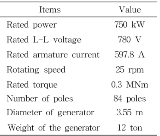
Table 1 shows the specifications of the 750 kW-class HTS generator.
Therefore, CLs should be designed optimally for reducing the conduction and Joule heat loads. This paper deals with a structural design and thermal analysis of a module coil for a 750 kW-class HTS generator. The conduction and radiation heat loads of the module coils were analysed using a 3D finite element method program. As a result, the total thermal load was less than the cooling capacity of the cryo-cooler. The design results can be effectively utilized to develop a superconducting generator for wind power generation systems.
Key Words : Current Lead, Cryo-cooler, High Temperature Superconducting Generator, HTS Module Coil, Thermal Analysis
Fig. 1 Design of the 750 kW-class HTS generator
Items Value
Rated power 750 kW
Rated L-L voltage 780 V Rated armature current 597.8 A Rotating speed 25 rpm
Rated torque 0.3 MNm
Number of poles 84 poles Diameter of generator 3.55 m Weight of the generator 12 ton Table 1 Specifications of the 750 kW-class
HTS generator
2.2 Design of the modularized HTS field coil
The HTS module coil consists of HTS field coils, coil bobbins, supports, a copper block, the CLs, a cryostat, and a cooling pipe. To prevent iron loss, stainless steel is used as the material of the cryostat. The coil supports are made of glass-fiber reinforced plastic (GFRP) to improve the heat insulation between the cryostat and the HTS coils. The HTS coils are covered with bobbin and bobbin supports to protect the HTS coils from a high mechanical force.
Fig. 2 shows the structural design of the HTS module coils. The 84 HTS module coils were divided into 14 parts. Each part was mounted on a cryostat with a copper block and cooling pipes. The liquid neon gas flows inside the cooling pipes to cool the HTS module coils. The HTS coils consist of three double pancake coils. The HTS wire of the rotor coil is coated with long flat conductor tape with a thickness of 0.15 mm and a width of 12 mm.
Fig. 2 Structural design of the HTS module coil
2.2.1 Structural design of the current lead The conduction and Joule heat loads of the CLs made of brass were calculated mathematically and analyzed. The minimum heat load and ideal length of the CL can be calculated by equations (1) and (2) [4].
(1)
(2)
The thermal conductivity and the electric resistivity are inversely related, according to Wiedemann-Franz law (3).
(3)
where, the Lorentz number is
×
, is the length of the CL, is the cross-sectional area, and is the carrying current,
and
represent the temperature of the cold and warm ends,
is the thermal conductivity, and is the electric resistivity [12].
Fig. 3 shows the structural design of the CL for HTS module coil. The CLs, including brass current terminals and current feedthrough, were designed using the 3D CAD program.
The length and thickness of the CL were 100 mm and 7.7 mm, respectively.
Fig. 3 Structural design of the CL
3. Thermal Analysis of the HTS Module Coil
The total thermal load of the HTS module coil, including the Joule heat, the conduction heat load of the CLs and radiation heat load, and the conduction heat load from supports were considered using the 3D FEM program.
The total heat load of the CL includes Joule heat and the heat invasion at room temperature. The heat invasion of the CL is obtained by varying the thickness of CL as shown in Fig. 4 and should be closed to 0 W.
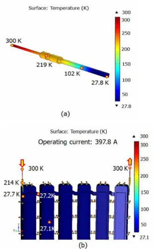
For the simulation, the operating current was 397.8 A. The temperature distribution analysis results of the designed CLs is shown in Fig. 5 (a) and (b). The total heat load of one CL was 20.1 W.
Fig. 4 Heat invasion of the CL
Fig. 5 Temperature distributions of (a) one
CL and (b) CLs with HTS module
coil
The GFRP, which has low thermal conductivity was used for support to reduce conduction heat load. The conduction heat load of supports was analysed by using the 3D FEM program and compared with the calculation result. The length and conduction area of the support were 20 mm and 0.078 m
, respectively.
The radiation heat load was evaluated by the Stefan-Boltzmann equation using the 3D FEM program. The radiation heat load between the
layer of multi-layer insulations is estimated as [3]:
(4)
where, is the effective total thermal emissivity of the materials. The emissivity of 0.01 was applied, in this paper. is the Stefan Boltzmann constant,
and
are radiation temperature and enclosure temperature, respectively.
As a result, the temperature of the HTS coil was 27.1 K. The conduction heat load from the supports and the radiation heat loads were 39.4 W and 7.59 W, respectively. The conduction and Joule heat load from the CLs was 40.2 W. The total heat load of the 750 kW-class HTS generator was 87.14 W.
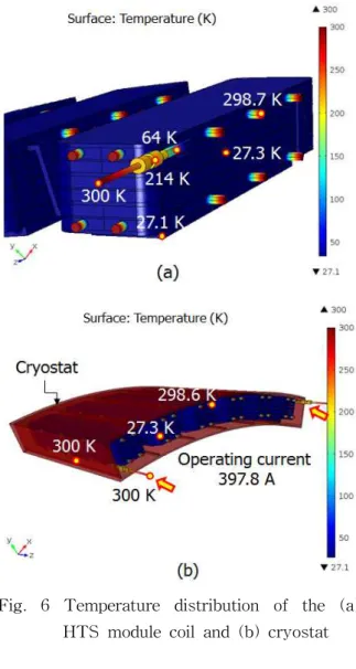
The temperature distribution analysis results of the HTS module coils are shown in Fig. 6. The temperature distributions in the HTS module coils and temperature distributions of the cryostat are shown in Fig. 6 (a) and (b), respectively.
Table 2 compares the calculation and simulation results. The total heat load obtained by the calculation and simulation
Fig. 6 Temperature distribution of the (a) HTS module coil and (b) cryostat
results were 75.05 W and 87.14 W, respectively.
The temperature was 27.1 K, which was
achieved less than 30 K. The AL325
cryo-cooler was used to cool the HTS
module coils. Based on the capacity map of
the cryo-cooler, the total heat load should be
less than 140 W, thus the cooling capacity
margin of the HTS module coil was 52.9 W.
Items Calculation result
Simulation result Conduction and
Joule heat load from the CLs
37.2 W 40.2 W Current terminals and
joint 0.35 W 0.35 W
Conduction heat load from the supports
32.9 W 39.4 W Radiation heat load 4.6 W 7.59 W Total heat load 75.05 W 87.14 W Table 2 The total heat load of the HTS module coil
4. Conclusions
This paper discussed the structural design and thermal analysis of a module coil for a 750 kW-class high temperature superconducting generator for wind turbine. The total heat loads were analyzed using a 3D FEM program.
The design procedure was performed at an operating temperature of 30 K, and the overall heat load of the HTS module coil was less than the cooling capacity of the cryo-cooler. The simulation results were compared with calculation results. As a result, the conduction heat load from the supports was 39.4 W, and the radiation heat load was 7.59 W, the Joule heat load of the current terminal and the joint was 0.35 W, the Joule and conduction heat loads from the CLs was 40.2 W. The total heat load and the temperature of the HTS module coil were 87.14 W and 27.1 K, respectively. The AL325 single-stage cryo-cooler was adopted to cool the HTS module coils. Overall heat load of the HTS module coil was less than the cooling capacity of the cryo-cooler, and the cooling capacity margin was 52.9 W. The
structural design and thermal analysis results of the HTS module coil can be effectively utilized in the development of a superconducting generator for wind power generation systems.
Acknowledgements
This research was supported by Changwon National University in 2017-2018.
References