Performance analysis of a 746 W HTS generator equipped with 70 A class contactless superconducting field exciter
6
0
0
전체 글
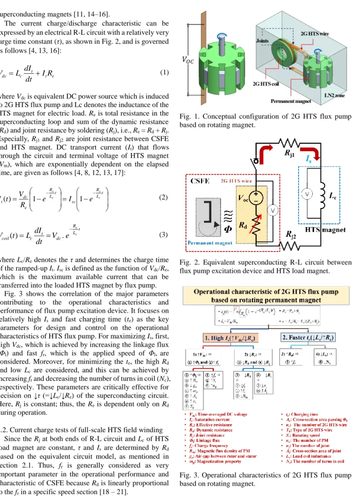
(2) 2. Performance analysis of a 746 W HTS generator equipped with 70 A class contactless superconducting field exciter. superconducting magnets [11, 14–16]. The current charge/discharge characteristic can be expressed by an electrical R-L circuit with a relatively very large time constant (τ), as shown in Fig. 2, and is governed as follows [4, 13, 16]:. Vdc Lc. dI t I t Re dt. (1). where Vdc is equivalent DC power source which is induced to 2G HTS flux pump and Lc denotes the inductance of the HTS magnet for electric load. Re is total resistance in the superconducting loop and sum of the dynamic resistance (Rd) and joint resistance by soldering (Rj), i.e., Re = Rd + Rj. Especially, Rj1 and Rj2 are joint resistance between CSFE and HTS magnet. DC transport current (It) that flows through the circuit and terminal voltage of HTS magnet (Vm), which are exponentially dependent on the elapsed time, are given as follows [4, 8, 12, 13, 17]:. I t (t ) . R R et et Vdc 1 e Lc I sc 1 e Lc Re . Fig. 1. Conceptual configuration of 2G HTS flux pump based on rotating magnet.. (2). Re. t dI Vcoil (t ) Lc t Vdc . e Lc dt. (3). where Lc/Re denotes the τ and determines the charge time of the ramped-up It. Isc is defined as the function of Vdc/Re, which is the maximum available current that can be transferred into the loaded HTS magnet by flux pump. Fig. 3 shows the correlation of the major parameters contributing to the operational characteristics and performance of flux pump excitation device. It focuses on relatively high Is and fast charging time (te) as the key parameters for design and control on the operational characteristics of HTS flux pump. For maximizing Is, first, high Vdc, which is achieved by increasing the linkage flux (Φl) and fast fr, which is the applied speed of Φl, are considered. Moreover, for minimizing the te, the high Rd and low Lc are considered, and this can be achieved by increasing fr and decreasing the number of turns in coil (Nc), respectively. These parameters are critically effective for decision on ↓τ (=↓Lc/↓Re) of the superconducting circuit. Here, Rj is constant; thus, the Re is dependent only on Rd during operation. 2.2. Current charge tests of full-scale HTS field winding Since the Rj at both ends of R-L circuit and Lc of HTS load magnet are constant, τ and Is are determined by Rd based on the equivalent circuit model, as mentioned in section 2.1. Thus, fr is generally considered as very important parameter in the operational performance and characteristic of CSFE because Rd is linearly proportional to the fr in a specific speed section [18 – 21]. Fig. 4 shows the three-dimensional configuration of fullscale HTS field winding assembled with CSFE. The 2G HTS wires with 12 mm width from SuperPower Inc. (SC12050 model) were wound on four-salient field poles. Fig. 2. Equivalent superconducting R-L circuit between flux pump excitation device and HTS load magnet.. Fig. 3. Operational characteristics of 2G HTS flux pump based on rotating magnet. with single racetrack formation. The averaged value of Ic for four-HTS field winding was measured to be 128 A at 77 K and self-field. The 2G HTS wires with 12.1 mm width from SuNAM Co., Ltd (SCN12550 model) were wound in.
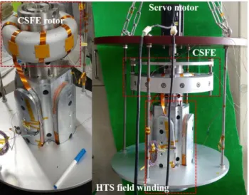
(3) Yoon Seok Chae, and Ho Min Kim. series on aluminum toroidal head of CSFE rotor and their two ends were mechanically jointed with two ends of HTS field winding using In-Bi soldering to create the electrically-closed circuit. The T-shaped neodymium magnets with a surface center magnetic flux density of 0.52 T (N50) were used for CSFE stator [22 – 24]. Fig. 5 shows experimental setup for current charge tests. In the tests, the CSFE stator, where the N50 PMs were installed, was the only rotating part for simplicity of the test environment. A servomotor operated and controlled this rotating part and its Ns (or fr). However, CSFE’s stator is stationary in real-operation of HTSG. The assembly between CSFE and HTS field winding was finally inserted into the cylindrical SUS cryostat to cool down by liquid nitrogen bath. The magnetic field density of the PM for the N50 grade was measured to be approximately 0.15 T at LN2 temperature, i.e., 77 K, and air-gap of 7 mm which is defined to geometric distance between the rotor and stator of CSFE [23]. In this experiment, the number of PMs (np) in the CSFE stator was considered to control the fr (= np Ns)/60) of CSFE. Thus, we changed the np from 4 to 16 with Ns under 200 rpm to investigate the operational characteristic and performance of Is charged by CSFE according to changes in the fr. Figs. 6 and 7 show the experimental results of the current charge tests according to the changes in np from 4 to 16 with different values of Ns (100, 150, and 200 rpm). Generally, the magnitude and charge speed of Is are enhanced with an increase in fr, as mentioned in section 2.1. The chargeable current ranges for full-scale HTS field winding were approximately from 49.5 to 70.4 A at fr values from 6.7 to 53.3 Hz. Moreover, the charging time (te) was calculated based on the time constant during the circuit charge, which means the elapsed time reaching 63.2% of Is, and they were compared in Table I. It was observed that te was generally accelerated with increasing fr. Finally, it concluded that to control the Is values below 49.6 A, the magnetic flux linked to 2G HTS wires of the CSFE rotor should be decreased by controlling air-gap length in this system [23]. The excitation loss of developed CSFE was compared with that of metal current lead pairs in contact excitation system. If HTS field winding was excited with current of 70.4 A by the contact excitation system, the excitation losses in copper- and brass-current lead pairs with round. 3. Fig. 5. Experimental setup of non-contact current charge tests for HTS field winding of 746 W HTSG.. Fig. 6. Is curves according to changes in np (= 4 and 8) and Ns (= 100, 150, and 200 rpm).. Fig. 7. Is curves according to changes in np (= 12 and 16) and Ns (= 100, 150, and 200 rpm).. Fig. 4. Three-dimensional configuration of full-scale HTS field winding assembled with CSFE.. rods were estimated to be 11.94 W (= 5.97 W 2 pairs) and 8.98 W (= 4.49 W 2 pairs), respectively, as shown in Fig. 8. Here, we calculated the minimum lead diameters of 3.4 and 7.8 mm in case of copper and brass materials, respectively, with an assumption of 330 mm axial length, which is considered by structural distance between end at.
(4) Performance analysis of a 746 W HTS generator equipped with 70 A class contactless superconducting field exciter. TABLE I CHARGING TEST RESULTS ACCORDING TO THE CHANGES IN FR. Charging Max. charge Test cases time†/current# current [A] [s]/[A] 4 PMs at 100 rpm (6.7 Hz) 1660/31.3 49.5 4 PMs at 150 rpm (10 Hz). 1280/36.5. 57.7. 4 PMs at 200 rpm (13.3 Hz). 922/37.5. 59.3. 8 PMs at 100 rpm (13.3 Hz). 795/36.1. 57. 8 PMs at 150 rpm (20 Hz). 690/40.5. 64.1. 8 PMs at 200 rpm (26.7 Hz). 582/43.3. 68.4. 12 PMs at 100 rpm (20 Hz). 886/39.2. 62. 12 PMs at 150 rpm (30 Hz). 564/41.4. 65.5. 12 PMs at 200 rpm (40 Hz). 439/44.5. 70.4. 16 PMs at 100 rpm (26.7Hz). 524/43.4. 68.6. 16 PMs at 150 rpm (40 Hz). 400/43.6. 68.9. 16 PMs at 200 rpm (53.3 Hz). 304/44.5. 70.4. †. : Charging time to reach 0.632Is, #: 0.632Is. TABLE II DESIGN PARAMETER SPECIFICATIONS OF THE 746 W HTSG. Parameters Unit Value Rated power W 746 Rated rotating speed rpm 400 Rotor pole number 4 Number of slots 48 Stator coil number per 52/416 slot/phase Fill factor of stator slot % 58 Magnetic air-gap mm 7 Mechanical air-gap mm 1 Operating field winding current A ≥40 Critical current of field winding A 127.5 Total inductance of field mH 32.9 winding Total turns of field winding 240 HTS coil type Race-track DPC Polyimide tape Winding type insulation Operating temperature K 77 Cooling method LN2 batch. Fig. 9. 2-D FEA model and mesh plot. Magnetic Field Intensity H2 [A/m] 0. 2000. 4000. 6000. 8000. 2.0. 10000 2.0. 1.5. 1.5 S18 (H1 - B1) S45C (H2 - B2). 1.0. 0.5. 1.0. 0.5. 0.0 0. 10000. 20000. 30000. 40000. Magnetic Field Density B2 [T]. 300 K and end at 77 K of round rod-type lead. Moreover, we considered averaged electrical resistivity (ρ) and thermal conductivity (k) from 300 K to 77 K (ρcopper = 460 W/mK and kcopper = 17.5 nΩ) and (ρbrass = 65 W/mK and kbrass = 70 nΩ) [25 – 26]. However, if the HTS field winding was charged by the CSFE, the excitation loss was estimated to be 0.54 W, with an assumption of Re of 0.1086 mΩ. It is observed that the values of Re (=Lc/τ) can be roughly calculated with Is test result of 70.4 A charge case, as shown in Fig. 7. In an equal operating condition, the 70 A class CSFE is possible to reduce the excitation loss by approximately 95.5% and 94%, respectively, as compared to that of the copper- and brass-current leads in conventional contact excitation system [24].. Magnetic Flux Density B1 [T]. 4. 0.0 50000. Magnetic Field Intensity H1 [A/m]. Fig. 10. B–H characteristic curves for stator core (S18) and rotor core (S45C).. Fig. 8. Variations in heat loss versus diameters of the (a) copper- and (b) brass-current lead.. Fig. 11. Ei comparison in armature open circuit of the 746 W HTSG at Ns of 100, 150, and 200 rpm..
(5) Yoon Seok Chae, and Ho Min Kim. 5. 3. OUTPUT CHARACTERISTIC ANALYSIS Table II lists the design parameter specifications of a 746 W HTSG to build 2-D FE models as shown in Fig. 9. The carbon steel (SAE-AISI 1045 or S45C) and laminated thin steel plates (50PN470 or S18) were used as the material for the iron cores in rotor and stator, respectively. Fig. 10 shows the magnetic field density (B) versus intensity (H) characteristic curves of the stator and rotor cores, which are referred from [27 – 28]. For non-loaded and loaded operations in the generator mode, the time-step 2-D FEA in ANSYS Electromagnetics Suite 19.0 release was carried out using approximately 5692 finite elements, as shown in Fig. 9. Fig. 11 shows the open circuit curves of the 746 W HTSG at the various Ns using If information based on non-contact current charge tests in Table 1. It shows the induced voltage (Ei) in the armature winding according to each Ns corresponding to excited If by CSFE. Based on Faraday's law, the Ei in the armature winding is proportional to the main magnetic field from field winding which is linked with the armature winding and its Ns. Thus, the high Ns and the large np in the CSFE stator exhibited the larger Ei in the armature winding, as shown in Fig. 11 because the If, which increases main magnetic field, is proportional to the np. When comparing the np of 12 and 16 at 200 rpm, the values of charged If are practically the same as 70.4 A even though the Φl in CSFE increased according to an increase of np in CSFE stator; thus, the magnitudes of the Ei are also the same. The generated ranges of Ei were calculated from 93.9 to 101.56 Vrms at the rated rotating speed of 200 rpm. Fig. 12 shows the 2-D magnetic field distributions for the 746 W HTSG in open circuit condition. As analysis result, it was confirmed that the magnetic cores in rotor and stator start to saturate within the controllable ranges of the If in this CSFE. Together, the values of Ei start to saturate as shown in Fig. 10. Fig. 13 shows the analysis results in constant load of the 746 W HTSG according to changes in np (If) and Ns. A constant resistive load of 30 ohm was electrically connected with 2-D FE model. As analysis result, it was confirmed that the output powers of over 746 W, which is the rated capacity of this machine, were generated above the fr values of 13.3 (4 PMs, 200 rpm), 26.7 (8 PMs, 200 rpm), 40 (12 PMs, 200 rpm), and 53.3 (16 PMs, 200 rpm) Hz. In conclusion, the If values of over 60 A are required to achieve the rated design of this machine through proper excitation combinations with np and Ns. Figs. 14 and 15 show the constant speed curves of the 746 W HTSG with the If of 49.5 A and the Ns of 100 rpm and the If of 70.4 A and the Ns of 200 rpm, respectively, according to changes in load resistance. In case of field excitation with the If of 49.5 A (fr = 6.7 Hz), it was not possible to generate the target capacity of this HTSG. In case of field excitation with the If of 70.4 A (fr = 40 and 53.3 Hz), the rated output power of 955 W was generated with terminal voltage of 175.8 Vrms and armature current of 3.1 Arms.. Fig. 12. 2-D magnetic field distributions at If charges of (a) 49.5, (b) 62, (c) 70.4 A in open circuit analysis.. Fig. 13. Constant load analysis results of the 746 W HTSG at load resistance of 30 ohm.. Fig. 14. Constant speed curves of 746 W HTSG at If of 49.5 A and Ns of 100 rpm..
(6) 6. Performance analysis of a 746 W HTS generator equipped with 70 A class contactless superconducting field exciter. [7]. [8]. [9]. [10]. [11] [12]. Fig. 15. Constant speed curves of 746 W HTSG at If of 70.4 A and Ns of 200 rpm.. 4. CONCLUSION In the preliminary charge tests, HTS field winding of the 746 W HTSG was successfully charged by 70 A class CSFE and its charge characteristics according to changes in the fr. Moreover, 2-D electromagnetic FEA was performed based on If information in non-contact current charge tests to estimate the output characteristics of HTSG. It is positively possible to generate the rated output of 746 W using the If excitation of over 60 A with the fr values of 13.3, 26.7, 40, and 53.3 Hz. All test and analysis results can be used as a technical reference for practical implementation and characteristic test of prototype HTSG equipped with 70 A class CSFE.. [13]. [14]. [15]. [16] [17]. [18]. [19]. [20]. ACKNOWLEDGMENT This work was supported in part by the National Research Foundation of Korea (NRF) grant funded by the Korea government (MSIT), Republic of Korea, and by Korea Electric Power Corporation. (Nos. 2019R1A2C1004715 and R18XA03). [21]. [22]. [23]. REFERENCES [1]. [2]. [3]. [4]. [5]. [6]. C. Hoffmann, D. Pooke, and A. D. Caplin, “Flux pump for HTS magnets,” IEEE Trans. Appl. Supercond., vol. 21, no. 3, pp. 16281631, 2011. C. Hoffmann, R. Walsh, E. Karrer-Mueller, and D. Pooke, “Design parameters for an HTS flux pump,” Phys. Proc., vol. 36, pp. 13241329, 2012. R. M. Walsh, R. Slade, P. Donald, and C. Hoffmann, “Characterization of current stability in an HTS NMR system energized by an HTS flux pump,” IEEE Trans. Appl. Supercond., vol. 24, no. 3, Jun. 2014, Art. no. 4600805. Z. Jiang et al., “A novel rotating HTS flux pump incorporating a ferromagnetic circuit,” IEEE Trans Appl. Supercond., vol. 26, no. 2, Mar. 2016, Art. no. 4900706. T. A. Coombs, J. F. Fagnard, and K. Matsuda, “Magnetization of 2G coils and artificial bulks,” IEEE Trans. Appl. Supercond., vol. 24, no. 5, Oct. 2014, Art. no. 8201005. T. A. Coombs, J. Geng, L. Fu, and K. Matsuda, “An Overview of flux pumps for HTS Coils,” IEEE Trans Appl. Supercond., vol. 27, no. 4, Jun. 2017, Art. no. 4600806.. [24]. [25]. [26]. [27]. [28]. C. W. Bumby, et al., “Through-wall excitation of a magnet coil by an external-rotor HTS flux pump,” IEEE Trans Appl. Supercond., vol. 26, no. 3, Jun. 2016, Art. no. 0500505. C. W. Bumby et al., “Development of a brushless HTS exciter for a 10 kW HTS synchronous generator,” Supercond. Sci. Technol., vol. 29, Jan. 2016, Art. no. 024008. V. Grinenko, G. Fuchs, J. Geng, and H. Zhang, “Dynamic resistance in a slab-like superconductor with Jc (B) dependence,” Supercond. Sci. Technol., vol. 12, pp. 382–387, 1999. J. Geng et al., “Origin of dc voltage in type II superconducting flux pumps: Field, field rate of change, and current density dependence of resistivity,” J. Phys. D, Appl. Phys., vol. 49, no. 11, 2016, Art. no. 11LT01. Z. Jiang et al., “Dynamic resistance of a high-Tc superconducting flux pump,” Appl. Phys. Lett., vol. 105, 2016, Art. no. 112601. C. W. Bumby, et al., “Frequency dependent behavior of a dynamotype HTS flux pump,” IEEE Trans Appl. Supercond., vol. 27, no. 4, Jun. 2017, Art. no. 5200705. Z. Jiang et al., “Impact of flux gap upon dynamic resistance of a rotating HTS flux pump,” Supercond. Sci. Technol., vol. 28, Sep. 2015, Art. no. 115008. C. W. Bumby et al., “Anomalous open-circuit voltage from a highTc superconducting dynamo,” Appl. Phys. Lett., vol. 108, no. 12, Mar. 2016. Art. no. 122601. R. C. Mataira et al., “Origin of the DC output voltage from a highTc superconducting dynamo,” Appl. Phys. Lett., vol. 114, no. 16, Apr. 2019. Art. no. 162601. Z. Jiang et al., “Dynamic resistance of a high-Tc superconducting flux pump,” Appl. Phys. Lett., vol. 105, Sept. 2014. Art. no. 112601. A. E. Pantoja et al., “Impact of stator wire width on output of a dynamo-type HTS flux pump,” IEEE Trans. Appl. Supercond., vol. 26, no. 8, Dec. 2016, Art. no. 4805208. J. Lee et al., “Experimental analysis of charging characteristics of HTS FCs with HTS contactless rotary excitation device considering various HTS loads,” IEEE Trans. Appl. Supercond., vol. 28, no. 3, Apr. 2018, Art. no. 5203105. H. Jeon et al., “Methods for increasing the saturation current and charging speed of a rotary HTS flux-pump to charge the FC of a synchronous motor,” IEEE Trans. Appl. Supercond., vol. 28, no. 3, Apr. 2018, Art. no. 5202605. H. Jeon et al., “PID control of an electromagnet-based rotary HTS flux pump for maintaining constant field in HTS synchronous motors,” IEEE Trans. Appl. Supercond., vol. 28, no. 4, Jun. 2018, Art. no. 5207605. S. Han et al., “Charging characteristics of rotary HTS flux pump with several superconducting wires,” IEEE Trans. Appl. Supercond., vol. 29, no. 5, Aug. 2019, Art. no. 0603605. J. H. Kim et al., “Design, analysis, and fabrication of salient fieldpole for a 1-kW- HTS rotating machine,” Cryogenics, vol. 97, pp. 126-132, 2019. J. H. Kim et al., “Fabrication and charging test of HTS field windings using HTS contactless rotary excitation,” IEEE Trans. Appl. Supercond., vol. 29, no. 5, Aug. 2019, Art. no. 5203207. J. H. Kim et al., “Fabrication and performance testing of a 1-kWhigh-temperature superconducting generator with a hightemperature superconducting contactless field exciter,” Supercond. Sci. Technol., vol. 33, Jul. 2020, Art. no. 095003. C. J. Hyeon et al., “Conceptual design of cooling anchor for current lead on HTS field coils,” Progr. Supercond. Cryogenics, vol. 19, no. 2, pp. 38–43, 2017. T. D. Le et al., “Conceptual design of current lead for large scale high temperature superconducting rotating machine,” Progr. Supercond. Cryogenics, vol. 16, no. 2, pp. 54–58, 2014. Non-oriented electrical steel surface insulation, August. 22, 2017. [Online].Available:http://www.posco.co.kr/homepage/docs/eng5/d n/company/product/e_electrical_pdf_2011.pdf Lorenz J, Fowler JT. “Synchronous generator subtransient reactance prediction using transient circuit coupled electromagnetic analyses and odd periodic symmetry,” August 22, 2017. [Online]. Available:http://studylib.net/doc/18175531/synchronousgenerator-subtransient-reactance..
(7)
수치


관련 문서
the records have a unique identifier field or field combination called the primary
produces a magnetic field which can be guided by a magnetic yoke to a linear Hall sensor; the output of the sensor is proportional to the electric current..
9.6 Calculus Review: Functions of Several Variables 9.7 Gradients of a Scalar Field. Directional Derivative 9.8 Divergence of a Vector Field. 9.9 Curl of a Vector Field 9.9 Curl
The stain field associated with a dislocation can in certain cases provide a favorable interaction with the strain field of the martensite nucleus, such that one of the
In this paper, the variable capacitors and the superconducting relay antenna were applied to the superconducting WPT system to increase efficiency and the transmission distance
A Study on the Wireless Power Transmission of magnetic resonance using Superconducting
For irrotational flow of ideal incompressible fluid, the Bernoulli’s equation applies over the whole flow field with a single energy line. Exact velocity field
Based on the efforts of the lower open stage where they expanded open areas by strengthening continually the Chinese trade field, international cooperative relationship
