- 27 -
Quasi-static Characteristics in Radial Direction of 100 kWh Class Superconductor Bearing
S. Y. Jung
*, B. J. Park, Y. H. Han, B. C. Park, J. P. Lee, S. C. Han
Korea Electric Power Research Institute, Daejeon, Korea
(Received 27 August 2010 revised or reviewed 16 September 2010 accepted 27 September 2010)
100 kWh급 초전도 베어링의 지름방향 준정적 특성
정세용
*, 박병준, 한영희, 박병철, 이정필, 한상철
Abstract
A superconductor flywheel energy storage system (SFES) is an electro-mechanical battery which transforms electrical energy into mechanical energy for storage, and vice versa. Many aspects of the quasi-static behavior of flywheel rotors still need to be studied closely, and the rotors require a stable and highly efficient supporting system such as high temperature superconductor (HTS) bearings, which offer dynamic stability without the use of active control. Quasi-static properties of HTS bearings in the radial direction provide data to solve problems which may occur in a running system. Since stiffness in countering rotor vibration is the main parameter for designing an HTS bearing system, we investigated the quasi-static properties of the magnetic force between permanent magnets(PMs) and HTS bulks in the radial direction. We measured radial stiffness, and discovered that bearing stiffness varied greatly depending on the number of active HTS bulks. This is valuable data for predicting the change in stiffness during partial HTS bearing failure. The quasi-static test results are used for optimal design and performance prediction for the 100 kWh class superconductor bearing.
Keywords : Superconductor Flywheel Energy Storage System, Electro-mechanical battery, Superconductor bearing, HTS bulk
I. Introduction
A superconductor flywheel energy storage system (SFES) is an electro-mechanical battery which transforms electrical energy into mechanical energy for storage, and vice versa.
Energy storage systems have been developed for application to
uninterruptible power supplies (UPS), power quality improvement, storage of distributed power sources such as solar and wind power, and load leveling.
Especially, superconductor flywheel energy storage systems using high temperature superconductors (HTSs) are capable of long term energy storage with very low energy loss [1-4]. An SFES consists of a composite flywheel with high energy density, a highly efficient motor/generator, a vacuum chamber, and non-contact HTS bearings, and these HTS
*Corresponding author. e-mail : [email protected] Tel : +82-42-865-5335 Fax : +82-42-865-5679
bearings allow for very low frictional losses, which lead to high rotational speeds and storage capacities.
The HTS bearing, which offers dynamic stability without the use of active control, is the key technology that distinguishes the SFES from other flywheel energy storage devices [5-8]. During the operation of the SFES, the system shows unstable running conditions due to unpredictable factors, which lead to lower operation efficiency [9]. These unpredictable factors must be controlled through the optimal design of superconductor bearings. Stiffness of an HTS bearing is the main index for evaluating the capacity of an HTS bearing and is determined by the magnetic force between the HTS bulks and the permanent magnet (PM) rotor.
High capacity HTS bearings will be applied to the 100 kWh class SFES for efficient storage of electric power. The HTS bearing is composed of a stator with dozens of HTS bulks mounted on the outer surface, and a rotor consisting of permanent magnet rings magnetized in the axial direction. Since stiffness in countering rotor vibration is the main parameter for designing an HTS bearing system, we investigated the quasi-static properties of the magnetic force between permanent magnets(PMs) and HTS bearings in the radial direction. We measured radial stiffness, and discovered that bearing stiffness varied greatly depending on the number of active HTS bulks. This is valuable data for predicting the change in stiffness during partial HTS bearing failure. The quasi-static test results are used for optimal design and performance prediction for the 100 kWh class superconductor bearing.
II. 100 kWh Class Superconductor Bearing
As shown in Fig. 1, a 100 kWh class superconductor bearing for application to SFES is composed of a stator with HTS bulks fixed to its outer surface and a rotor assembled with permanent magnet rings magnetized in the axial direction. Four HTS bulks are fixed to each bearing module of the stator (Fig. 2(a)), and the modules are designed to
provide enough fixing force while preventing any damage to the HTS bulks due to different degrees of thermal expansion of each material involved. In addition, materials with high thermal conductivity are used to manufacture the modules for more efficient cooling of the HTS bulks. The cryostat of the bearing stator is cooled by circulating subcooled liquid nitrogen.
The permanent magnet rings of the rotor are magnetized in the axial direction, and are assembled so that like poles are facing each other. Pure iron shims with high magnetic permeability are placed between the permanent magnet rings so that high magnetic flux density is formed at the HTS bulks. As shown in the partial model in Fig. 2(b), shims are mounted between each permanent magnet to create the desired magnetic field.
Fig. 1. 100 kWh class superconductor bearing.
(a) (b)
Fig. 2. (a) HTS bearing module (b) HTS bearing rotor partial model.
III. Experimental Setup and Procedure
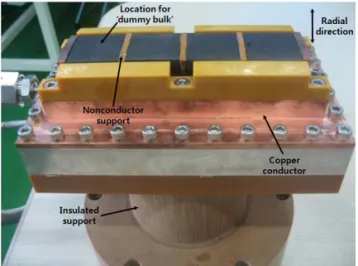
100 kWh class HTS bearing partial modelIn this study, an HTS bearing partial model was assembled, as shown in Fig. 3, for a more accurate measurement of the radial stiffness of the bearing.
One module from the 100 kWh class superconductor bearing in Fig. 1 was mounted on an insulated support with the HTS bulks facing upward, in accordance with the direction of motion of the universal testing machine in Fig. 4. The universal testing machine moves the HTS bearing rotor partial model in the ‘radial direction’, shown in Fig. 3.
PT-100 temperature sensors were used to measure the temperature of the HTS bulks and other critical points, and a spacer was prepared to fix the gap between the partial model stator and rotor during field cooling.
Fig. 3. HTS bearing partial model for radial stiffness measurement.
Cooling system & universal testing machine
The cooling system used for this study is composed of 3 GM cryocoolers with 120W@77K capacity, a cryo-pump for circulating the subcooled liquid nitrogen, several vacuum insulated corrugated pipes connecting the cryocoolers with the HTS bearing partial model, and heaters at strategic locations for controlling the temperature of the liquid nitrogen. Although the HTS bearing partial model
used in this study requires less than 10 W of cooling capacity, a system with a much larger capacity was selected to compensate for any additional heat invasion. The temperature of all the HTS bulks was maintained at 79 K for all procedures.
In order to measure the stiffness of the HTS bearing partial model in the radial direction, a vacuum chamber was mounted to a single-axis universal testing machine (Instron 8871), as shown in Fig. 4. The universal testing machine controls the gap between the stator and rotor of the HTS bearing partial model, while measuring the attractive or repulsive force. All of the experiments were performed in a clean and dry vacuum environment, preventing any degradation in the HTS bulks.
Fig. 4. HTS bearing partial model testing equipment.
Quasi-static stiffness in radial direction
Radial stiffness of the HTS bearing partial model
was measured according to the number of active HTS
bulks. Four HTS bulks were mounted on the HTS
bearing module at a position where the movement of
the subrotor would simulate the vibration of the HTS
bearing in the radial direction. The universal testing
machine shifted the position of the subrotor in the
radial direction in the range of ±1 mm at 1mm/sec,
after field cooling with a 2 mm gap between the HTS
bulks of the substator and the permanent magnets of
the HTS rotor. With the same setting, 1 HTS bulk
was replaced by a ‘dummy’ bulk to represent the
failure of one of the HTS bulks on the module. The location of the HTS bulk replaced by the ‘dummy’
bulk is shown in Fig. 3. The universal testing machine moved the subrotor in the radial direction of the 3-bulk substator module, in the range of ±1 mm at 1mm/sec, after field cooling with a 2 mm gap between the HTS bulk of the substator and the permanent magnet of the HTS rotor.
IV. Results and Discussion
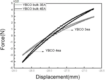
The results of the ‘quasi-static stiffness in radial direction’ are shown in Fig. 5. The x-axis represents the displacement of the subrotor from the field cooled position. It can be seen that the position of the subrotor was shifted in the range of ±1 mm. The y-axis represents the magnetic force between the substator and subrotor according to displacement.
Force at the field cooled position is 0 kgf. The black and gray plotted lines represent the results for the 4-bulk and 3-bulk substator modules, respectively.
The results for both 4-bulk and 3-bulk cases are not linear due to hysteresis. Therefore, the stiffness of the HTS bearing partial model is different at every shifted position. For comparative purposes, the average values for both cases were used. The average values were calculated by assuming that stiffness is linear between the end values at -1 mm and + 1mm.
Fig. 5. Quasi-static stiffness in radial direction.
The average stiffness for the 4-bulk substator module is 4.13 kgf/mm, which gives an average stiffness of 1.03 kgf/mm for each bulk. On the other hand, the average stiffness for the 3-bulk substator module is 2.97 kgf/mm, which gives an average stiffness of 0.99 kgf/mm for each bulk. The average stiffness of each HTS bulk for the 4-bulk substator module is 4% higher than the 3-bulk substator, and it can be assumed that this minor difference is due to the different properties between the individual HTS bulks, as well as the minor field cooling gap difference and cooling temperature of the two cases.
The total average stiffness for the 4-bulk and 3-bulk substator modules is the sum of the radial stiffness of each HTS bulk. This result can be used to calculate the expected radial stiffness of the 100 kWh class HTS bearing in case of partial failure, where only some of the HTS bulks lose superconductivity due to quenching .
IV. Conclusion
In this paper, the stiffness characteristics of a 100 kWh class HTS bearing partial model in the radial direction were studied. A 4-bulk and 3-bulk substator module was mounted to the substator of the HTS bearing partial model, and the radial stiffness was measured with a universal testing machine. The average radial stiffness value for each HTS bulk of the 4-bulk and 3-bulk case showed a difference of 4%, which can be considered to be within allowance range. It can be concluded that the total radial stiffness of the HTS bearing partial model is the sum of the radial stiffness of each HTS bulk. This result can be used to calculate the expected radial stiffness of the 100 kWh class HTS bearing in case of partial failure, and can be applied to the design of the HTS bearing for the 100 kWh SFES.
References
[1] Y. H. Han, J. R. Hull, S. C. Han, N. H. Jeong, T. H.
Sung, and Kwangsoo No, “Design and characteristics of a superconductor bearing” IEEE Tran. Vol. 15, No.
2 (2005).
[2] N. Kosizuka, “R&D of superconducting bearing technologies for flywheel energy storage systems”, Physica C 445-448, pp. 1103-1108 (2006).
[3] Coombs, T. et al., “Superconducting magnetic bearings for energy storage flywheels”, IEEE Trans. Applied Supercon. vol. 9, pp. 968-971 (1999).
[4] A. C. Day, J. R. Hull et al, “Temperature and frequency effects in a high-performance superconducting bearing”, IEEE Trans. On Applied superconductivity, Vol. 13, No. 2, pp. 2179-2184 (2003).
[5] G. Krabbes, G. Fuchs, W.-R. Canders, H. May, R.
Palka, High Temperature Superconductor Bulk Materials, WILEY-VCH, pp. 75-104 (2006).
[6] T. H. Sung, S. C. Han, Y. H. Han, J. S. Lee, N. H.
Jeong, S. D. Hwang and S. K. Choi, “Design and
analysis of flywheel energy storage system using High-Tc superconductor bearings”, Cryogenics 42, pp.
357-362 (2002).
[7] T. Ichihara, K. Matsunaga, M. Kita, I. Hirabayashi et al, “Application of superconducting magnetic bearings to 10 kWh-class flywheel energy storage system”, IEEE Trans. on Applied Superconductivity, Vol. 15.
No. 2, pp. 2245-2248 (2005).
[8] R. Shiraishi, K. Demachi, M. Uesaka, and R. Takahata,
“Numerical and experimental analysis of the rotation speed degradation of superconducting magnetic bearings”, IEEE Trans. on Applied Superconductivity, Vol. 13, Nol. 2. pp. 2279-2282 (2003).
[9] I. Masaie, K. Demachi, T. Ichihara and M. Uesaka,
“Numerical evaluation of rotational speed degradation in the superconducting magnetic bearing for various superconducting bulk shapes”, IEEE Trans. on Applied Superconductivity, Vol. 15, No. 2, pp. 2257-2260 (2005).