Journal of the Korea Institute for Structural Maintenance and Inspection Vol. 16, No. 6, November 2012, pp.102-112
http://dx.doi.org/10.11112/jksmi.2012.16.6.102
pISSN 2234-6937 eISSN 2287-6979
스터럽 절단 탄소섬유판 표면매립공법의 휨 보강 성능 평가
Assessment of Flexural Strengthening Behavior Using the Stirrup-Cutting Near Surface Mounted(CNSM) CFRP strip
문 도 영1) 오 홍 섭2)* 지 광 습3)
Moon, Do Young Oh, Hong Seob Zi, Goang Seup
Abstract
Recently, the near surface mounted (NSM) FRP strengthening technique has been actively applied to deteriorated concrete structures for rehabilitation purposes. However, the use of this conventional NSM technique could be restricted due to the insufficient height or strength of the concrete cover. In this study, the stirrup-Cutting Near Surface Mounted(CNSM) technique was considered as an alternative, whereby NSM strips are placed at a deeper level, namely at the level of the main steel reinforcement. A flexural test of a concrete beam strengthened with CNSM technique was performed and the results were then compared to those for a concrete beam strengthened by the conventional NSM technique. The embedment length of the CFRP strips was varied in order to increase the effect of the anchoring depth of the NSM and CNSM CFRP strips in the beam specimens. From the results of the test, the beam with the CNSM CFRP strip showed typical structural behavior similar to that of the beam with the NSM CFRP strip. Moreover, there was no apparent structural degradation resulting from the stirrup partial-cutting. Consequently, the CNSM strengthening technique can be suitably utilized for extensively damaged concrete structures where it is difficult to apply the conventional NSM technique.
Keywords : Stirrup, CNSM, Flexural test, Rehabilitation
1) 경성대학교 토목공학과
2) 경남과학기술대학교 토목공학과, 교신저자 3) 고려대학교 토목공학과
* Corresponding author : [email protected] 055-751-3299
• 본 논문에 대한 토의를 2012년 12월 31일까지 학회로 보내주시면 2013년 1월호에 토론결과를 게재하겠습니다.
Copyright Ⓒ 2012 by The Korea Institute for Structural Maintenance and Inspection. This is an Open Access article distributed under the terms of the Creative Commons Attribution Non-Commercial License (http://creativecommons.org/licenses/by-nc/3.0)which permits unrestricted non-commercial use, distribution, and reproduction in any medium, provided the original work is properly cited.
1. INTRODUCTION
The key issue with the externally bonded fiber reinforced plastics strengthening technique has been premature bonding failure. It is well known that concrete structures such as a beams, slabs, and columns that are strengthened with EBR prematurely fail in a brittle manner, before reaching its design strength, due to delamination of the bonded FRP laminates.(Derias and El-Hacha, 2007; Seracino et al., 2007; Barros et al., 2006; Yoon et al., 2011) In order to overcome this problem, a strengthening technique using a near surface mounted (NSM) CFRP
strip or bar has been developed.(Liu et al, 2006;
Oehlers and Seracino, 2006; Rizkalla et al, 2003;
Hassan and Rizkalla, 2004; Bonaldo et al, 200;
El-Hacha et al., 2004; Kishi et al 2005; Seo et al.
2012) In the NSM technique, the CRFP strengthening material was embedded in notches cut into the concrete cover and the notches were filled with epoxy resin. In this way, the CFRP can be effectively protected from direct exposure to an unexpected fire or to a chemically aggressive environment. As expected, the premature failure mentioned above remarkably decreased with the application of the NSM technique due to the superior bond it provides
with the concrete, while the load carrying capacity of the structure greatly improved. In addition, it has been reported that the NSM technique has less sensitivity to surface preparation and has a more consistent quality compared to the EB technique.
(Derias and El-Hacha, 2007)
In an ordinary steel reinforced concrete structure, the concrete cover plays an important role in durability and serviceability and provides the initial barrier to aggressive environmental attack. In the flexural strengthening technique with NSM, the concrete cover is an important component that anchors the NSM FRP strips and transfers the load directly to the CFRP strengthening material through the bond between the concrete and the CFRP/epoxy. Therefore, the concrete cover should be kept in a sound condition during the service of the structure. However, because the concrete cover can easily deteriorate due to unexpected loads, such as impact, fire, etc., it is difficult to maintain a sound concrete cover zone. A more feasible method should therefore be considered to enhance the integrity of the rehabilitation system with NSM. In this study, an alternative method is attempted, whereby CFRP strips are inserted at a deeper location. However, this alternative method requires partial cutting of the existing stirrups with an enclosed shape, which interrupts the installation of CFRP strips. Therefore, before this method can be employed in an actual deficient reinforced concrete beam, an experimental investigation of the effect of the partial cutting of stirrups is necessary in terms of the flexural behavior and load carrying capacity of beams with NSM.
In this study, the stirrup-Cutting Near Surface Mounted (CNSM) CFRP strip technique, where the CFRP strip is installed at a deeper level than the NSM technique, was evaluated through flexural tests and the results were compared with the conventional NSM technique. The number and the embedment length of the CFRP strip were considered as a test variables in order to clearly observe the effect of
the partial cutting of stirrups on the failure mode and load carrying capacity between both strengthening techniques. The failure modes and load-deflection curves and moment capacity are presented in this paper.
2. EXPERIMENT PROGRAM
2.1 Materials
CFRP strips produced by a Korean manufacturer were used. The width and thickness of each strip was 25mm and 1.2mm, respectively. The CFRP strips have a tensile strength of 3160 MPa and a modulus of elasticity of 165 GPa, as provided by the manufacturer. Epoxy adhesive was used for bonding the strips to the surrounding concrete.
Normal weight ready-mixed concrete was used for the specimens. The average compressive strength of concrete was 30 MPa as evaluated by tests on three cylindrical 100 mm high specimens. Ordinary steel rebars were used and their yield strength and elastic modulus were found to be 600 MPa and 200 GPa, respectively, based on the tensile tests specified in KS B 0801(KS, 1981)
2.2 Test Variables
Table 1 shows the test specimen. Fourteen beam specimens were cast for this experimental program, including two non-strengthened beams, which were used as control specimens. Stirrups with a closed shape were distributed at 100mm spacing along the beam axis over the entire length. The shear strength of the test beam can be computed by equation (1) in accordance with ACI 318-08(ACI, 2008). In equation (1), the shear strength of the control beams provided by the concrete and stirrups was found to be 80kN and 119kN, respectively.
Half of the strengthened beams were strengthened using the NSM technique with one or two CFRP
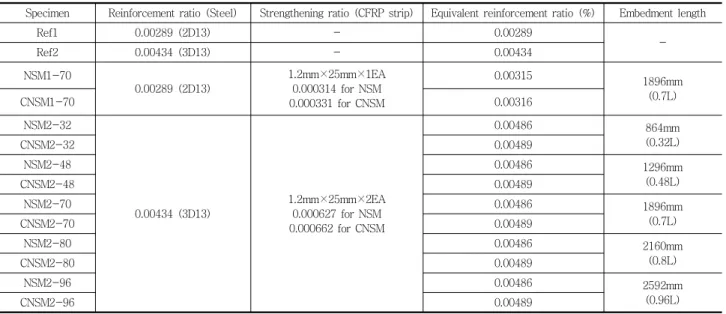
Table 1 Test specimens
Specimen Reinforcement ratio (Steel) Strengthening ratio (CFRP strip) Equivalent reinforcement ratio (%) Embedment length
Ref1 0.00289 (2D13) - 0.00289
Ref2 0.00434 (3D13) - 0.00434 -
NSM1-70
0.00289 (2D13)
1.2mm×25mm×1EA 0.000314 for NSM 0.000331 for CNSM
0.00315 1896mm
(0.7L)
CNSM1-70 0.00316
NSM2-32
0.00434 (3D13)
1.2mm×25mm×2EA 0.000627 for NSM 0.000662 for CNSM
0.00486 864mm
(0.32L)
CNSM2-32 0.00489
NSM2-48 0.00486 1296mm
(0.48L)
CNSM2-48 0.00489
NSM2-70 0.00486 1896mm
(0.7L)
CNSM2-70 0.00489
NSM2-80 0.00486 2160mm
(0.8L)
CNSM2-80 0.00489
NSM2-96 0.00486 2592mm
(0.96L)
CNSM2-96 0.00489
Fig. 1 Details of cross section (units in mm)
strips and the other half were strengthened using the CNSM technique with one or two CFRP strips as shown in Figure 1. As indicated by Barros et al (2007), Kang et al.(2005), and Seracino et al.
(2007), the failure and ultimate behavior of a beam strengthened with NSM are significantly influenced by the geometry slit, the distance between FRP elements, and the distance of FRP elements to the edges of the beam. Therefore, for the beam with two CFRP strips, the distance between FRP elements was set at 40mm to prevent mutual interference and the distance of the CFRP elements to the beams edges was symmetrically set at 94mm to prevent surface spalling of the edge of the concrete cover, in accordance with the recommendation provided by Kang et al.(2005).
The mechanism of IC debonding was investigated analytically by Seracino et al.(2007). The minimum embedment length of the CFRP strips of the test beam was set at 864mm, which corresponds to 32% of the net span length, in order to prevent the IC debonding failure. The embedment length of the CFRP strip in beams was varied in order to investigate the change in the failure mode and moment capacity of a beam strengthened with NSM and CNSM CFRP strips. The considered embedment lengths were
Fig. 2 Test setup and measuring positions(units in mm) Fig. 3 Failure mode for beam NSM2-32
32%, 48%, 70%, 80%, and 90% of the net span length of the beam. The names of specimens comprise the name of the strengthening technique, that of NSM or CNSM, and the number of the CFRP strip, that of 1 or 2, and the embedment length of the CFRP strip, that of 32, 48, 70, 80, or 96, as listed in Table 1.
′
(1)
where, ′, are the compressive strengths of concrete at 28 days and the yield strength of steel reinforcement, respectively; and b, d are the beam width and the distance from extreme compression fiber to the centroid of the longitudinal tension reinforcement, respectively; and, and s are the area and spacing, respectively, of shear reinforcement.
2.3 Test setup and measurements
Four point flexural tests were carried out using the test configuration shown in Fig. 2. However, the loading points at mid-span were spaced at only 160mm. From this test configuration, it is expected that the effect of the partial cutting of stirrups on the behavior of the beam can be understood because the whole span of the beam will be acting under shear force.
In addition, more convenient loading work was accomplished with the configuration. The beams were instrumented with a linear variable differential transducer (LVDT) at midspan and at 675mm from each support in order to measure the deflection. At
midspan, a strain gauge was glued to the top fiber of the concrete in the compression zone using an epoxy resin after carefully sandblasting the concrete.
In the midsection of all beams, the steel and CFRP strip in the tension zone were instrumented with strain gauges that were positioned before casting.
The transducer and strain gauge positions are shown in Fig. 2.
3. TEST RESULTS
3.1 Mode of failure
The failure modes of all tested beams are summarized in Table 3. For beam NSM2-32, the crack appeared in the vicinity of the cutoff section of the CFRP strip as shown in Figure 3. As the load increased, the crack propagated horizontally at the level of the steel tension reinforcement, eventually causing the beam to fail. This is identified as debonding failure, according to the study carried out by Teng et al. (2006). Conversely, beam CNSM2-32 collapsed, not because of debonding, but due to concrete crushing in the compression zone after yielding of the steel tension reinforcement. These results indicated that the debonding phenomenon can be mitigated by the increased anchoring depth of the CNSM CFRP strips.
The NSM and CNSM, beams, also strengthened
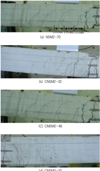
(a) NSM2-70
(b) CNSM2-32
(C) CMSM2-48
(d) CNSM2-70
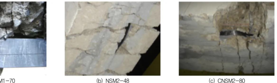
Fig. 5 Inclined cracks between loading points and supports (a) NSM2-80
(b) NSM2-80
(c) NSM2-48
(d) CNSM2-96
Fig. 4 Failure by concrete crushing
with both techniques, failed in the typical flexural mode due to concrete crushing. In the mid span, vertical cracks were occurred at the initial cracking load. These cracks increased to the compression zone with an increase in the load. In some specimens, the concrete cover at the compression zone spalled off during the tests, as illustrated in Figure 4.
On the other hand, in beams with two CFRP strips, inclined cracks appeared in between the loading point and the support. However, these cracks were limited to the spacing of stirrups as shown in Figures 3-5. The occurrence of these inclined cracks can be explained by the shear force exceeding the shear strength provided by the concrete, which is about 80kN, as mentioned above. The inclined cracks
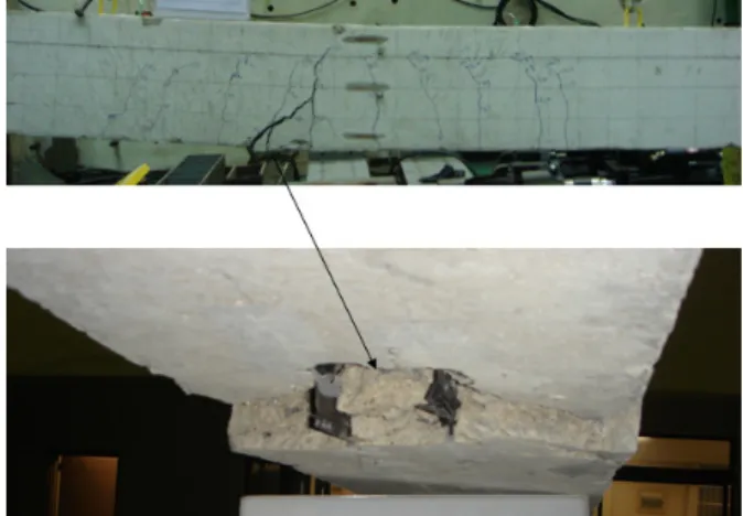
were formed in almost the same way for both the NSM and the CNSM series beams. From these observations, it was found that there was a negligible effect of the partial cutting of stirrups on the flexural behavior of the tested beam.After the failure of the beam, the concrete in the tension zone was carefully removed in order to inspect in detail the status of the CFRP strip.
As shown in Figure 6, the embedded CFRP strips were split longitudinally and were buckled locally due to a large deformation. Based on these results, it can be assumed that in both techniques the embedded CFRP strips could have been partly damaged or buckled before the failure of the beam.
Fig. 7 Comparisons of Load-midspan deflection curves of control beams and strengthened beam with one CFRP strip
(a) NSM1-70 (b) NSM2-48 (c) CNSM2-80
Fig. 6 Damaged or locally buckled CFRP strips
3.2 Load-deflection curves
For all beams that failed due to concrete crushing, up until the time of failure, two-time reductions in slope were observed. The first of these was caused by initial cracking in the concrete in the tension zone, which indicates that the steel rebar and the CFRP reinforcement would actively resist the increments of tensile force from this point. The second slope reduction occurred when the load was slightly greater than the yield load of the steel rebar, which indicates that only the CFRP reinforcement would resist increments of tensile force from the external load from this point.
In Figure 7 a comparison is presented of the load-midspan deflection curves between the control beams, Ref1 and Ref2, and the strengthened beams with both techniques, NSM1-70 and CNSM1-70.
Beam CNSM1-70 exhibited nearly the same flexural
stiffness as that of beams Ref1 and Ref2, and yielded at a load greater than that of beam Ref1, yet smaller than that of beam Ref2. Conversely, beam NSM1-70 showed the highest stiffness, yet yielded at nearly the same load level as that for beam CNSM1-70. These results revealed that the increase in the yield and failure load of both strengthened beams was achieved by the strengthening of the CFRP strip. However, the flexural stiffness of both strengthened beams was strongly dependent on the depth from the concrete fiber to the CFRP strip. It should be noted that the FRP element in the CNSM strengthening technique is inserted more deeply than that in the NSM strengthening technique.
Therefore, the depth to the FRP element in the beam strengthened with the CNSM technique is nearly the same as the depth of the steel rebar in the beam prior to rehabilitation, resulting in a decrease the distance between the compression and tensile forces of the internal resisting couple.
Figure 8 shows the load-midspan deflection of beams NSM2-70 and CNSM2-70 and these are compared to those of beam Ref2. It is shown that the ultimate load and yield load of beam Ref 2 were significantly increased by using both strengthening techniques. However, a greater stiffness was observed in beam NSM2-70 due to the greater depth to the CFRP reinforcement.
For the CNSM strengthening technique, the effect of the embedment length of the CFRP on the load carrying capacity is shown in Figure 9. When the
Fig. 8 Comparisons of Load-midspan deflection curves of control beams and strengthened beam with two CFRP strips
Fig. 9 Load-midspan deflection curves of beams strengthened with CNSM technique
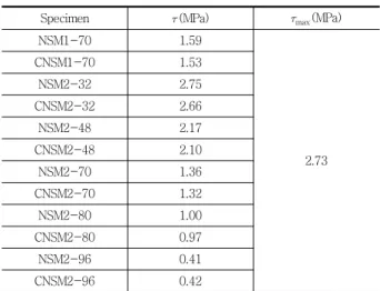
Table 2 Shear stress at cut off position of CFRP strips
Specimen (MPa) max(MPa)
NSM1-70 1.59
2.73
CNSM1-70 1.53
NSM2-32 2.75
CNSM2-32 2.66
NSM2-48 2.17
CNSM2-48 2.10
NSM2-70 1.36
CNSM2-70 1.32
NSM2-80 1.00
CNSM2-80 0.97
NSM2-96 0.41
CNSM2-96 0.42
embedment length of the CFRP strip was below the 50% of the net span of the beam, the beam collapsed at a very early stage. The load and deflection at the failure of beams CNSM2-32 and 48 were only around 83% and 61% of those of beams CNSM2-70, 80 and 96. These significant reductions in failure load and in the amount of deflection seemed to be caused by an inability to develop the tensile capacity of the CFRP strips due to the insufficient embedment length of the CFRP reinforcement.
Similar results can be found in the study carried out by Hassan et al.(2003), where flexural tests of beams strengthened with different embedment lengths of NSM CFRP strips were performed. In their study, it was reported that the composite action between
the embedded CFRP strip and the concrete was partially lost by flexural cracks at midspan and that the ultimate load and corresponding deflection could be significantly reduced by the flexural cracks, particularly in the beams with an embedment length shorter than 68% of the net span length. In addition, a model was presented for the calculation of the development length of the NSM CFRP strips as shown in the following equation (2) and was evaluated by a parametric study. The maximum critical shear stress is also given by equation (3).
(2)m ax ′
′
(3)
All parameters in equations (2) and (3) are defined in Hassan et al.(2005). In this present study, for all the strengthened beams, the shear stress, , when P is equal to 80kN at the cut off position of the CFRP strips was calculated by equation (2). The results were summarized in Table 2. The shear stress increased with a decrease in the embedment length of the CFRP strip and with an increase in the reinforcement ratio. It was shown that the debonding failure of beam NSM2-32 was accurately predicted
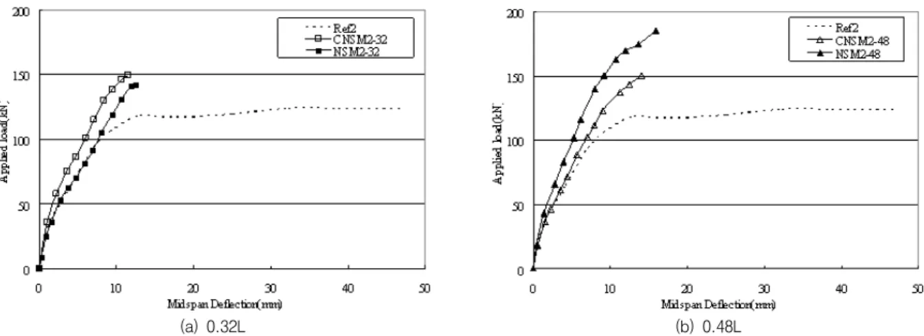
(a) 0.32L (b) 0.48L Fig. 10 Comparison of load-midspan deflection curves
by the model proposed by Hassan et al.(2005). In particular, the shear stress decreased insignificantly by 3~4% in the beams with CNSM CFRP strips compared to the beams with NSM CFRP strips.
Figure 10 presents a comparison between both strengthening techniques. With the exception of beam NSM2-32, there was no significant difference in the load-deflection behavior for both strengthening techniques. The flexural stiffness of beam NSM2-32 was identical to that of beam Ref2 despite the strengthening provided by the CFRP strips. This is due to the debonding of the CFRP strips at the initial stage. In addition, a significant decrease in the maximum load and in the amount of deflection were shown in the beams that had an embedment length of 32% and 48% of the net span length, regardless of which strengthening technique was applied. These results suggest that when applying the CNSM technique, the CFRP strips should have a minimum length of not less than 70% of the net span length in order to be fully anchored to the concrete.
3.3 Moment capacity
The strengthening efficiency was evaluated in terms of the normalized moment capacity in order to account of the effect of the different depth to the CFRP strips on the flexural capacity. The moment (m axexp)
was divided by in order that it could be presented using stress units. Table 3 provides a summary of the normalized moment capacity for all tested beams.
The increment in the last column of Table 3 is defined as the ratio of the normalized moment of the strengthened beam to that of the control beam.
The increase in the normalized moment capacity was greater when the CNSM technique was applied.
Moreover, the normalized moment capacity of beam CNSM2-32 increased by more 16% compared to NSM2-32 due to the change in the failure mode.
From these comparisons, it can be seen that the CNSM technique can be effectively used for concrete structures that require appropriate rehabilitation yet have a limited or severely deteriorated concrete cover.
In order to seek an appropriate design scheme for the CNSM technique, the prediction model of the moment capacity specified in ACI 440.2R-02 was investigated. However, as indicated by Barros et al.(2007), the formulation to evaluate the effective strain of NSM FRP has not yet been recommended in the ACI design guide(2002). Therefore, in this study, the relationship of the effective strain of the NSM CFRP strip and the equivalent reinforcement ratio performed by Barros et al. (2007) was employed in the calculation of the ACI formulation for the moment capacity. The relationship was taken from the regression analysis of the numerous experimental
Table 3 Test results of the tested beams
Specimen Initial cracking load (kN) Failure Pattern maxexp(kN) maxexp(kN m) Normalized moment (MPa) Ratio
Ref1 33 a)* 104.0 66.04 2.1 -
Ref2 28 a) 125.9 79.94 2.5 -
NSM1-70 29 b)** 136.7 86.89 2.4 114%
CNSM1-70 35 b) 126.7 80.45 2.5 119%
NSM2-32 35 c)*** 147.2 93.47 2.6 104%
CNSM2-32 38 b) 152.2 96.65 3.0 120%
NSM2-48 32 b) 185.1 117.54 3.2 128%
CNSM2-48 35 b) 150.2 95.38 2.9 116%
NSM2-70 35 b) 192.6 122.30 3.4 136%
CNSM2-70 35 b) 190.3 120.84 3.7 148%
NSM2-80 31 b) 173.2 109.98 3.0 120%
CNSM2-80 36 b) 189.4 120.27 3.7 148%
NSM2-96 33 b) 191.8 121.79 3.4 136%
CNSM2-96 39 b) 171.6 108.97 3.3 132%
*a) Steel yielding
**b) Crushing of concrete and steel yielding
***c) Debonding of the NSM CFRP strips (Concrete split failure)
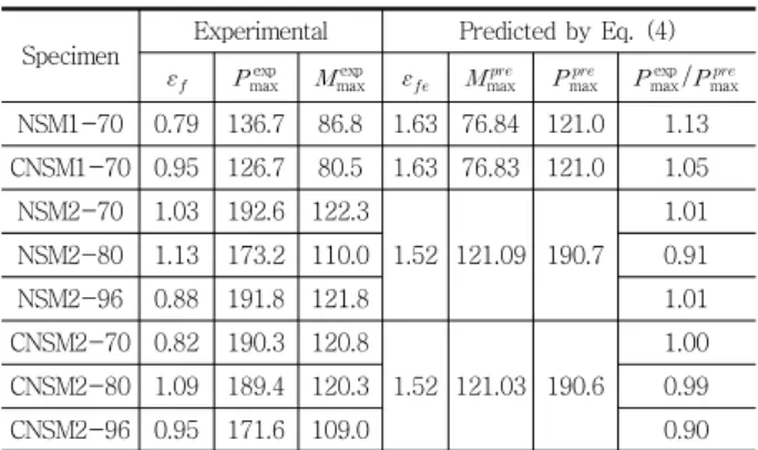
Table 4 Comparisons of ultimate loads obtained from experiment and prediction model
Specimen Experimental Predicted by Eq. (4)
maxexp maxexp max max maxexp/max
NSM1-70 0.79 136.7 86.8 1.63 76.84 121.0 1.13 CNSM1-70 0.95 126.7 80.5 1.63 76.83 121.0 1.05
NSM2-70 1.03 192.6 122.3
1.52 121.09 190.7 1.01
NSM2-80 1.13 173.2 110.0 0.91
NSM2-96 0.88 191.8 121.8 1.01
CNSM2-70 0.82 190.3 120.8
1.52 121.03 190.6 1.00
CNSM2-80 1.09 189.4 120.3 0.99
CNSM2-96 0.95 171.6 109.0 0.90
results of beams strengthened with NSM FRP strips and is formulated as shown in equation (4).
(4)
where, and are the effective tensile strain at ultimate conditions and ultimate strain at the rupture point in the FRP, respectively. is the equivalent reinforcement ratio
The calculated results were compared with the experimental strain of the CFRP strip, as shown in Table 4. Significant differences were shown between
the experimental and predicted values in the strain of the CFRP strip. This may be caused by the presence of flexural cracks as well as by the errors in the regression analysis of the experimental results.
In addition, although the depth to the CFRP strip in the beams was altered in the NSM and CNSM strengthening techniques, the effect was not taken into account. Consequently, a well established model that can be used for the prediction of effective CFRP strain is still needed. Nevertheless, the predicted moment capacity concurred with the experimental results. Therefore, the ACI formulation and the relationship of the effective strain of the NSM CFRP strip can be utilized for the preliminary analysis and for the experiment of flexural member strengthened with CNSM technique.
4. CONCLUSIONS
Through flexural tests of beam specimens, the effect of the partial cutting of stirrups distributed along the beam axis was investigated for the installation of NSM FRP elements in concrete structures that have a limited or severely damaged
concrete cover. The beam specimens strengthened with NSM and CNSM CFRP strips and with different embedment lengths for the NSM CFRP strips were tested and compared with non-strengthened beams.
An investigation of the crack pattern revealed that the effect of the cutting of stirrups was insignificant in the given geometry of the tested beam. Furthermore the failure mode was altered from debonding to concrete crushing by an increase in the anchoring depth of the CNSM CFRP strips. In addition, when the CNSM CFPR strips have a sufficient length of not less than 70% of the net span length to achieve full composite action with the concrete, the load carrying capacity can be improved by around 40%.
Furthermore, based on the experimental observations, an identical flexural behavior to those beams that were strengthened with the conventional NSM technique was observed, which confirms that this CNSM strengthening technique can be effectively used for structurally deficient concrete structures that have a limited or severely damaged concrete cover.
ACKNOWLEDGEMENTS
This work was supported by the National Research Foundation of Korea funded by the Ministry of Education, Science and Technology(NRF-2010- 00245085) and Gyeongnam National University of Science and Technology.
REFERENCES
1. ACI committee 440. 2R., Guide for the design and construction of externally bonded FRP systems for strengthening concrete structures, American Concrete Institute, 24, 2002.
2. American Concrete Institute, Building code and commentary, ACI 318-08, Detroit, 155, 2008.
3. Barros JAO, Dias SJE, Lima JLT., Efficacy of CFRP- based techniques for the flexural and shear strengthening of concrete beams, J Cem Concr Compos, 29, 2007, 203-217.
4. Barros JAO, Ferreira DRSM, Fortes AS, Dias SJE., Assessing the effectiveness of embedding CFRP laminates in the near surface for structural strengthening, Constr
Build Mater, 20, 2006, 478-491.
5. Bonaldo E, Barros JAO, Lourenco PB., Efficient strengthening technique to increase the flexural resistance of existing RC slabs, J Compos Constr vol. 12, No. 2, 2008, 149-159.
6. Derias M, El-Hacha R., Bond behavior of FRP in structures: state-of-the-art review, Proc., 8th Int. Symp.
FRPRPs-8, Patras, Greece, 2007.
7. El-Hacha R, Filho JNS, Melo GS, Rizkalla S., Effectiveness of near surface mounted FRP reinforcement for flexural strengthening of reinforced concrete beams, Proc., 4th Int.ConfACMBS, Calgary, Canada, 2004.
8. Hassan T, Rizkalla S., Investigation of bond in concrete structures strengthened with near surface mounted carbon fiber reinforced polymer strips, J Compos Constr, vol.
7, No. 3, 2003, 248-257.
9. Hassan TK, Rizkalla SH., Bond mechanism of NSM FRP bars for Flexural Strengthening of concrete structures, ACI Struct J, vol. 101, No. 6, 2004, 830-839.
10. Kang J, Park Y, Park J, You Y, Jung W., Analytical evaluation of RC beams strengthened with near surface mounted CFRP laminates, Proc., 7th Int. Symp. FRPRPs-7, Kansas City, USA, 2005, 779-794.
11. Kishi N, Mikami H, Kurihashi Y, Sawada S., Flexural behavior of RC beams reinforced with NSM AFRP rods, Proc., Int. Symp. on Bond Behavior of FRP in Structures (BBFS2005), Hong Kong, 2005, 337-342.
12. Korea Industrial Standards, The pieces for tension test for metallic materials, KS B 0801, Korea(in Korean), 1981.
13. Liu IST, Oehlers DJ, Seracino R., Tests on the ductility of reinforced concrete beams retrofitted with FRP and steel near-surface mounted plates, J Compos Constr, vol. 10, No. 2, 2006, 106-114.
14. Rizkalla S, Hassan T, Hassan N., Design recommendations for the use of FRP for reinforcement and strengthening of concrete structures, Prog Struct Engng Mater, 5, 2003, 16-28.
15. Seo, S., Choi. K., Kwon. Y. Retrofit Capacity of Near- Surface-Mounted RC Beam by using FRP Plate, Journal of KSMI, vol. 16, No. 1, 18-26(in Korean)
16. Seracino R, Saifulnaz MRR, Oehlers DJ., Generic debonding resistance of EB and NSM plate-to-concrete joints, J Compos Constr, vol. 11, No. 1, 2007, 62-70.
17. Teng JG, De Lorenzis L, Wang B, Li R, Wong TN, Lam L., Debonding failures of RC beams strengthened with near surface mounted CFRP strips, J Compos Constr, vol. 10, No. 2, 2006, 92-105.
18. Yoon J., Han J. Cho D., Park S. Crack and Debonding Donitoring of RC Beams Strengthened with CFRP Plates, Journal of KSMI, vol. 15, No. 4, 185-192(in Korean).
Received : 09/18/2012 Revised : 10/17/2012 Accepted : 10/19/2012
요 지
최근 탄소섬유판 매립공법의 콘크리트 구조물의 보강에 적용되고 있다. 그러나 탄소섬유판 표면매립공법은 피복부 콘크리트의 강도 부족과 높이 부족 등으로 인하여 그 적용의 제한이 발생하기도 한다. 본 연구에서는 이와 같은 이유로 인하여 전단 스터럽 을 절단하고 탄소섬유판을 주철근의 위치에 표면매립 보강하는 공법에 대하여 고찰하였다. 일반적인 표면매립공법과 스터럽을 절 단하고 표면매립공법을 적용한 보에 대한 휨 실험을 수행하였으며, 결과를 서로 비교하였다. 탄소섬유판의 길이를 실험변수로 하 였다. 실험결과에 따르면, 전단 스터럽을 절단한 보강 보의 휨거동은 일반적인 표면매립공법이 적용된 실험체의 거동과 유사한 전 형적인 휨 거동을 나타내었으며, 스터럽의 절단으로 인한 구조거동상의 문제는 발생하지 않았다. 따라서, 일반적인 현장 여건에 의하여 탄소섬유판의 적용이 곤란한 경우에는 스터럽을 절단하는 본 공법의 적용이 가능한 것으로 판단된다.
핵심 용어 : 스터럽, 표면매립 탄소섬유판, 휨실험, 보강