INTRODUCTION
Since the Bra °nemark implant was introduced in dental therapy, many successful clinical applications have been reported. Osseointegration is no longer an issue in the success of implant treatment;
1-2instead, esthetic and mechanical stability in implant-supported restoration is the focus in dentistry today.
3,4The implant is not a natural tooth, so unsolved mechanical and biological problems of implant exist.
5-7To solve these problems, there have been many developments in shape, surface, materials, and surgical technique. In the current dental market, numerous types of implants are available and they are broadly divided into two groups by the type of joint between the abutment and fixture; internal and external implant/abutment connections.
8The external hexagonal connection has advantages such as suitability for a two-stage method, an anti-rotation mechanism, and retrievability and compatibility among different systems. It also has disadvantages: 1) micro- movements because of the size of the hex, 2) a higher center of rotation, which leads to lower resistance for rotational and lateral movements, and 3) a micro-gap leading to bone resorption. However, the weak-link to the external hexagonal type is often referred to as a fail-selfmechanism, which prevents more severe failure in overloading situations.
8-10The internal hexagonal connection is easy to connect to
the abutment without a radiograph for the fit of the joint, is suitable for a one-stage method, has higher stability and anti-rotation because of a wider area of connection and higher resistance to lateral loads because of the lower center of rotation; it also has better force distribution.
8-10Its disadvantages include a thinner lateral wall at the connecting part and difficulty in adjusting divergences in angles between fixtures.
Regardless of the kind of abutment, screw loosening has been reported as the most common factor of failure and reason for complaint in implant-supported restorations.
11-17The exact frequency of screw loosening has not been reported because this process is a result, in part, of differences in restoration designs and the large variability in biting force and habits between both people and different teeth in the same mouth.
18-20The preload is the most important factor for keeping a joint stable. It is developed in the stem of a screw when torque is applied to the screw. The screw, like a rubber band, is stretched within its head and mating thread; this makes a clamping force, which closely connects the two parts and makes a stable joint without movement.
9,17The purpose of this study is to assess the difference in abutment screw stability between the external and internal hexagonal connections under different cyclic loading conditions. This study adds to the understanding of joint stability in the two different systems under different loading cycles.
THE ASSESSMENT OF ABUTMENT SCREW STABILITY BETWEEN THE EXTERNAL AND INTERNAL HEXAGONAL JOINT
UNDER CYCLIC LOADING
Tae-Sik Lee1, DDS, MSD, Jung-Suk Han2*, DDS, MSD, PhD, Jae-Ho Yang2, DDS, MSD, PhD, Jae-Bong Lee2, DDS, MSD, PhD, Sung-Hun Kim3, DDS, PhD
1Graduate Student, 2Professor, 3Associate Professor,
Department of Prosthodontics, Graduate School, Seoul National University
Corresponding Author: Jung-Suk Han
Department of Prosthodontics School of Dentistry, Seoul National University
28 youngun-dong, Jongno-gu, Seoul, 110-749, Korea +82 2 992 7050: e-mail, [email protected] Received October 6, 2008 Last Revison December 8, 2008 Accepted December 9, 2008.
※This work was supported by the Korea Science and Engineering Foundation (KOSEF) grant funded by The Korean
government (MOST) (No. R01-2007-000-10977-0).
MATERIALS AND METHODS
First, the samples are divided into two groups by the type of connection: the external hexagonal connection is Group A and the internal hexagonal connection is Group B. Each group is further subdivided into an a (10 samples) and b (5 samples) according to the different loading cycles: a group used 1 × 10
6, and additional 5 × 10
6cyclic loading, and b group used 3 × 10
6, and additional 3 × 10
6cyclic loading.
Table I shows the groups and their components of implant fixtures and abutment.
Customized metal cap and customized jig
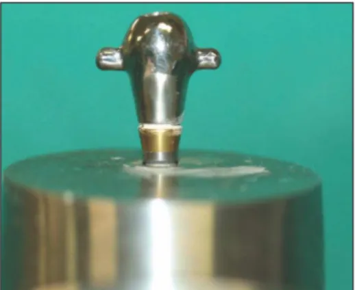
A customized metal cap and jig were made by ISO/DIS Standardization. The metal cap is shaped like a hemisphere in order to transfer a load to the center (Fig. 1 - 4). The loading force was applied to the hemisphere cap. The customized jig was designed to hold the implant fixture, and the distance is 3 mm from the implant platform to the exposed position of the fixture. The distance of 3 mm was
chosen to represent the worst case in bone retraction.
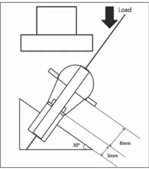
19The load was applied on the hemispheric metal cap at 30�and the distance is 11 mm from the center of the hemisphere to the exposed position of the fixture.
Applied torque and Cyclic loading
A total 6 × 10
6cyclic loading was applied to the abutments using different cyclic loading durations. In sub- type a group (10 samples), the removal torque value was recorded before loading, after 1 × 10
6cyclic loading, and after additional 5 × 10
6cyclic loading. Each removal torque value was evaluated with a digital torque gauge (Fig.
2), after which the abutment screw retightened to 30 N/cm and loading cycles were resumed. In sub-type b group (5 samples), the removal the removal torque value was recorded before loading, after 3 × 10
6cyclic loading, and after additional 3 × 10
6cyclic loading. Procedure of evaluating the removal torque value was same to the sub- type a group. Before conducting the cyclic loading, a procedure of tightening/loosening of the screw was repeated 5 times to remove micro irregularity of screw thread, and
Fig. 1. The specially customized metal cap; hemi- sphere shape in order to transmit the applied load to the center of abutment.
Fig. 2. Digital torque gauge (MGT12.mark-10. corp.
USA). All abutment screws were tightened to 30 N/cm
± 0.5 N/cm with this digital torque gauge and the removal torque values of the screws were recorded.
Table I. Materials of tested specimens
group Implant fixture Abutment
Group A implant fixtures of 4.0 mm (∅) × 11.5 mm (L) US cemented abutments hex regular external hexagonal connection 5.0[∅], 1.0[G/H], 5.5 mm[H]
(USⅡ, OSSTEM Co., Ltd, Korea) (GSⅡ, OSSTEM Co., Ltd, Korea)
Group B implant fixtures of 4.0 mm (∅) × 11.5 mm (L) transfer abutment hex standard 5.0[∅], 3.0[G/H], internal 11-degree hexagonal connection 5.5 mm[H], 11-degree hexagonal connection (GSⅡ, OSSTEM Co., Ltd, Korea) (GSⅡ, OSSTEM Co., Ltd, Korea) Abutment screw Ti-alloy : 90% Ti, 6% Al, 4% Vn (OSSTEM Co., Ltd, Korea)
then the screw was left alone for 3 minutes to recover its original state. Then, each sample is loaded in the cyclic loading machine (Instron model 8871. USA), which controls the 30 - 300 N/cm cyclic loading in an Hsine shape at 14 Hz (Fig. 4).
Statistical analysis
SPSS statistical software for Windows (ver. 13.0, SPSS Inc., Chicago, IL, USA) was used for statistical analysis.
Group means were calculated and compared by ANOVA, independent t-test, and paired t-test with α= 0.05.
RESULTS
Group A (External hexagonal connection)
In Group A-a, the mean removal torque value was 18.65 N/cm before cyclic loading, and 19.05 N/cm after 1 × 10
6cyclic loading. There was no significant difference in the torque value before and after 1 × 10
6cyclic loading (Table II). The mean removal torque value was 17.79 N/cm after total 6 × 10
6cyclic loading, which indicates a little loss of the preload, but it did not indicate a significant difference. In Group A-b, there was no significant difference in the removal t orque value before, after 3 × 10
6cycles (Table II), and after additional 3 × 10
6cyclic loading (Table II). In
Fig. 3. Schematic diagram of the specimen. The loadwas applied on the hemispheric metal cap at 30�and the distance was 11 mm from the exposed position of the fixture to the center of the hemisphere.
Fig. 5. Group A, B
Group A: External hexagonal connection of the abutment and fixture (Left).
Group B: Internal hexagonal connection of the abutment and fixture (Right).
Fig. 4. The specimen is mounted in the customized jig with 30�
inclined plane to be loaded with load machine (Instron model 8871.
USA).
A B
the comparison of Group A-a and Group A-b, the removal torque value was less in Group A-a (17.79 N/cm) than in Group A-b (18.78 N/cm) at total 6 × 10
6cycles, but it was not significant (Table III).
Group B (Internal hexagonal connection)
In Group B-a, the mean removal torque value was 18.65 N/cm before and 19.29 N/cm after cyclic loading. There was no significant difference in the torque value before and after 1 × 10
6cyclic loading (Table VI). The mean removal torque value was 11.4 0 N/cm after 6 × 10
6cyclic loading, which means a loss of the preload (t = 14.096, P < .05) (Table VI). In Group B-b, there was no significant difference in the removal torque value before loading and
after 3 × 10
6cycles (Table VI), and after 3 × 10
6, and additional 3 × 10
6cycles (Table VI) In the comparison of Group B-a and Group B-b, the removal torque value was less in Group B-a (11.40 N/cm) than in Group B-b (18.20 N/cm) at total 6 × 10
6cycles, and it was significant (t = - 10.694, P < .05) (Table V).
Comparison of Group A and Group B
The external hexagonal connection (Group A) was more stable than the internal hexagonal connection (Group B) after 1 × 10
6, and additional 5 × 10
6cyclic loading (t = 10.834, P < .001) (Table VI). There were no significant differences in the two systems after 3 × 10
6, and additional 3 × 10
6cycles.
Table II. Assessment of the removal torque value in Group A-a and Group A-b after cyclic loading
Group Cyclic loading Mean removal
SD t/p value
torque value (N/cm)
Before loading 30.16 0.21 1.801/.080
A-a 1 × 10⁶ 19.05 1.11 -.793/.433
1 × 10⁶, and additional 5 × 10⁶ 17.79 1.28 1.664/.104
Before loading 30.22 0.19 1.040/.306
A-b 3 × 10⁶ 19.36 0.64 -1.065/.295
3 × 10⁶, and additional 3 × 10⁶ 18.78 0.25 -.197/.845
Table III. Comparison of the removal torque value after total 6 × 10⁶cyclic loading between Group A-a and Group A-b
Group Cyclic loading Mean removal
SD t/p value
torque value (N/cm)
A-a 1 × 10⁶, and additional 5 × 10⁶ 17.79 1.28
A-b 3 × 10⁶, and additional 3 × 10⁶ 18.78 0.25 -1.673/.118
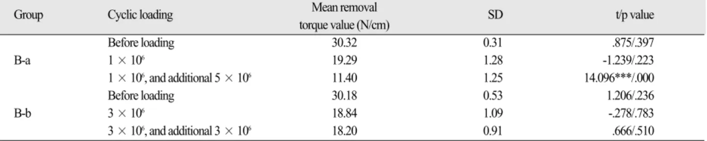
Table IV. Assessment of the removal torque value in Group B-a and Group B-b after cyclic loading
Group Cyclic loading Mean removal
SD t/p value
torque value (N/cm)
Before loading 30.32 0.31 .875/.397
B-a 1 × 10⁶ 19.29 1.28 -1.239/.223
1 × 10⁶, and additional 5 × 10⁶ 11.40 1.25 14.096***/.000
Before loading 30.18 0.53 1.206/.236
B-b 3 × 10⁶ 18.84 1.09 -.278/.783
3 × 10⁶, and additional 3 × 10⁶ 18.20 0.91 .666/.510
*** = significantly different (P < .001)
Table V . Comparison of the removal torque value after total 6 × 10⁶cyclic loading between Group A-a and Group A-b
Group Cyclic loading Mean removal
SD t/p value
torque value (N/cm)
B-a 1 × 10⁶, and additional 5 × 10⁶ 11.4 1.25
B-b 3 × 10⁶, and additional 3 × 10⁶ 18.2 0.91 -10.694***/.000
*** = significantly different (P < .001)
DISCUSSION
In implant prosthodontics, the stability of the joint has been shown to be a significant factor in stress transfer, biologic response of peri-implant host tissues, and screw loosening. When a screw is tightened, it is stretched between the head of screw and its thread. It has a tendency to rebound to its original state, and this creates a preload in the stem of the screw; this defines the screw tension force applied to the implant system, which creates a clamping force across the joint to prevent joint separation.
9.17The preload is influenced by several factors, such as screw material, applied torque value, screw friction, separating force of the joint, and the abutment fit.
Material properties of the screw influence the screw preload, especially the modulus of elasticity.
20,21Jo ¨rne ´us et al. reported that a gold screw with a flat head with 35 N/cm tightening torque produced the best results in conical head Ti grade 1, flat head Ti grade 1, flat head Ti grade 3, and flat head gold alloy.
9In this study, the Ti-alloyed screw (90% Ti, 6% Al, 4% Vn: OSSTEM Co, Ltd, Korea) was used, so if a gold screw was used, the removal torque value might be higher.
In this study, for accurate preload, the tightening/- loosening procedure was repeated 5 times for reducing the thread friction, which caused a reduced preload. The friction is higher at the first closing/opening of a screw cycle, making the surface irregularity smooth, but many repeated cycles cause the thread to become disengaged and deformed, so the procedure is limited to 5 times in this study.
18-20The screw was left for 3 minutes to return to its original state. The titanium abutment screw is tightened to 30 N/cm with a digital torque gauge, which makes preload
of the screw more reliable and controllable than the manual method (Fig. 2).
17,19The manufacturer recommends the torque value for its product, which is considered its material yield strength. In the clinic, applying the correct torque on the screw is the most important factor in preventing screw loosening, so in this study, the digital torque gauge was used to tighten the screw.
18, 21Friction between the screw and mating part of the implant determines how much torque force should be used during tightening to establish the preload. About 90% of the applied tightening force is lost; only 10% produces the preload, so reducing the surface texture increases the preload. After the screw is tightened, friction is important to secure the joint, and in an internal connection with an inner tapered abutment, friction between the taper interfaces contributes to joint stability.
10, 21-23If a bending force caused a load larger than the yield strength of the screw, a plastic permanent deformation resulted. In both systems, the point of plastic deformation or the critical zone was noted to be at the concave neck just above the abutment thread or abutment screw thread.
21In the Astra system, the point of plastic deformation was at the neck of the bridge screw just below the screw head;
whereas, for the external butt connection, it was at the concave zone above the thread of the abutment screw, because the lateral wall of the internal conical implant played a role of the dissipation of the load.
23-26In this study, no deformation of the screw was observed in external and internal connectional abutment.
The abutment fit is also a significant factor in screw loosening, stress transfer, and biologic response of peri- implant tissues. Jo ¨rne ´us et al. reached a similar conclusion:
screw joints could be made more resistant to screw
Table VI. Comparison of the removal torque value after cyclic loading between Group A and Group BCyclic loading Group Mean removal
SD t/p value
torque value (N/cm)
1 × 10⁶ A-a 19.05 1.11 -0.463
B-a 19.29 1.28 /.654
1 × 10⁶, and additional 5 × 10⁶ A-a 17.79 1.28 10.834***
B-a 11.40 1.25 /.000
3 × 10⁶ A-b 19.36 0.64 .808
B-a 18.84 1.09 /.465
3 × 10⁶, and additional 3 × 10⁶ A-b 18.78 0.26 1.329
B-a 18.20 0.91 /.255
*** = significantly different (P < .001)
loosening by the elimination of rotational misfit.
9In addition, Norton MR. used 8- and 11-degree internal cones (ITI and Astra) to determine the correlation between loosening and tightening torque in different taper types, but there were no significant differences.
27In this study, the 11 degree tapered internal hexagonal abutment (Group B) was used and its effect on the stability of the joint was not significant.
For many dental implants, it is known that the marginal bone will retract following implantation to a steady-level, so in this study,the distance 3 mm was chosen to provide a worst case with respect to bone retraction, and the cyclic loadings were applied to samples at 30�, which is more similar to the clinical state of anterior teeth.
19In this study, there was no effect of conical connection on screw stability (Group B); this result may be caused by the different pattern of stress distribution between the bone and this customized jig. The external hexagonal connection (Group A) was more stable than the internal hexagonal connection (Group B) after 1 × 10
6, and additional 5 × 10
6cyclic loading (t = 10.834, P < .001) (Table VI). There were no significant differences in the two systems after 3 × 10
6, and additional 3 × 10
6cycles (Table VI). A long-term study may be needed to assess the screw stability in these two different connection types.
The results of the study are limited to the mechanical point of the internal and external connection implant system; in addition, there was a small number of specimens and they were only tested under dry conditions. As biologic conditions such as saliva, heat, and corrosion may affect the abutment-implant interface, further research is needed to increase the understanding of the characteristics of this interface.
CONCLUSION
Abutment screw stability between an external and internal hexagonal connection was assessed under cyclic loading. From this study, the following may be concluded.
1. There was no significant difference in the removal torque values after 1 × 10
6cyclic loading, after 3 × 10
6cyclic loading, and after 3 × 10
6, and additional 3
× 10
6cyclic loading, respectively, between the
external hexagonal connection and the internal hexagonal connection.
2. In the internal hexagonal connection, compared to the removal torque value of the abutment screw at 1 × 10
6cyclic loading, the value after 1 × 10
6, and additional 5
× 10
6cyclic loading was reduced and the difference was significant (P < .001) (Table V).
3. The external hexagonal connection (Group A) was more stable than the internal hexagonal connection (Group B) after 1 × 10
6, and additional 5 × 10
6cyclic loading (t = 10.834, P < .001) (Table VI).
4. After 3 × 10
6, and additional 3 × 10
6cyclic loading situation, the difference of the removal torque value of the abutment screw between the external hexagonal connection and the internal hexagonal connection was not significant (Table VI).
REFERENCES
1. Bra °nemark PI, Hansson BO, Adell R, Breine U, Lindstro ¨m J, Halle ´n O, Ohman A. Osseointegrated implants in the treatment of the edentulous jaw. Experience from a 10-year period. Scand J Plast Reconstr Surg Suppl 1977;16:1-132.
2. Adell R, Lekholm U, Rockler B, Bra °nemark PI. A 15-year study of osseointegrated implants in the treatment of the edentulous jaw. Int J Oral Surg 1981;10:387-416.
3. Jemt T, Lekholm U. Oral implant treatment in posterior partially edentulous jaws: a 5-year follow-up report. Int J Oral Maxillofac Implants 1993;8:635-40.
4. Nevins M, Langer B. The successful application of os- seointegrated implants to the posterior jaw: a long-term ret- rospective study. Int J Oral Maxillofac Implants 1993;8:428-32.
5. Sones AD. Complications with osseointegrated implants. J Prosthet Dent 1989;62:581-5.
6. Zarb GA, Schmitt A. The longitudinal clinical effective- ness of osseointegrated dental implants: the Toronto study.
Part III: Problems and complications encountered. J Prosthet Dent 1990;64:185-94.
7. Jemt T, Linde ´n B, Lekholm U. Failures and complications in 127 consecutively placed fixed partial prostheses sup- ported by Bra °nemark implants: from prosthetic treatment to first annual checkup. Int J Oral Maxillofac Implants 1992;7:40-4.
8. Maeda Y, Satoh T, Sogo M. In vitro differences of stress concentrations for internal and external hex implant-abut- ment connections: a short communication. J Oral Rehabil 2006;33:75-8.
9. Jo ¨rne ´us L, Jemt T, Carlsson L. Loads and designs of screw
joints for single crowns supported by osseointegrated im- plants. Int J Oral Maxillofac Implants 1992;7:353-9.
10. Binon PP. The effect of implant/abutment hexagonal misfit on screw joint stability. Int J Prosthodont 1996;9:149-60.
11. Worthington P, Bolender CL, Taylor TD. The Swedish sys- tem of osseointegrated implants: problems and complica- tions encountered during a 4-year trial period. Int J Oral Maxillofac Implants 1987;2:77-84.
12. Zarb GA, Schmitt A. The longitudinal clinical effective- ness of osseointegrated dental implants: the Toronto study.
Part III: Problems and complications encountered. J Prosthet Dent 1990;64:185-94.
13. Hemmings KW, Schmitt A, Zarb GA. Complications and maintenance requirements for fixed prostheses and over- dentures in the edentulous mandible: a 5-year report. Int J Oral Maxillofac Implants 1994;9:191-6.
14. Kallus T, Bessing C. Loose gold screws frequently occur in full-arch fixed prostheses supported by osseointegrated im- plants after 5 years. Int J Oral Maxillofac Implants 1994;9:169-78.
15. Jemt T. Fixed implant-supported prostheses in the edentu- lous maxilla. A five year follow-up report. Clin Oral Implants Res 1994;5:142-7.
16. Schwartz-Arad D, Samet N, Samet N. Single tooth re- placement of missing molars: a retrospective study of 78 implants. J Periodontol 1999;70:449-54.
17. Binon PP. The external hexagonal interface and screw-joint stability: a primer on threaded fasteners. Quintessence Dent Technol 2000;23:91-105.
18. Haack JE, Sakaguchi RL, Sun T, Coffey JP. Elongation and preload stress in dental implant abutment screws. Int J Oral Maxillofac Implants 1995;10;529-36.
19. ISO/DIS 14801: Dental implants-Dynamic continuous fa- tigue test. 2003.
20. Haack JE, Sakaguchi RL, Sun T, Coffey JP. Determination of preload stress in dental implant screws. J Dent Res 1994;73:202.
21. Yousef H, Luke A, Ricci J, Weiner S. Analysis of changes in implant screws subject to occlusal loading: a preliminary analysis. Implant Dent 2005;14:378-82.
22. Norton MR. An in vitro evaluation of the strength of an in- ternal conical interface compared to a butt joint interface in implant design. Clin Oral Implants Res 1997;8:290-8.
23. Bahat O, Handelsman M. Use of wide implants and double implants in the posterior jaw: a clinical report. Int J Oral Maxillofac Implants 1996;11:379-86.
24. Arvidson K, Bystedt H, Frykholm A, von Konow L, Lothigius E. A 3-year clinical study of Astra dental im- plants in the treatment of edentulous mandibles. Int J Oral Maxillofac Implants 1992;7:321-9.
25. Vigolo P, Fonzi F, Majzoub Z, Cordioli G. An in vitro eval- uation of ZiReal abutments with hexagonal connection: in original state and following abutment preparation. Int J Oral Maxillofac Implants 2005;20:108-14.
26. Vigolo P, Fonzi F, Majzoub Z, Cordioli G. Evaluation of gold-machined UCLA-type abutments and CAD/CAM ti- tanium abutments with hexagonal external connection and with internal connection. Int J Oral Maxillofac Implants 2008;23:247-52.
27. Norton MR. Assessment of cold welding properties of the
internal conical interface of two commercially available
implant systems. J Prosthet Dent 1999;81:159-66.
THE ASSESSMENT OF ABUTMENT SCREW STABILITY BETWEEN
THE EXTERNAL AND INTERNAL HEXAGONAL JOINT UNDER CYCLIC LOADING
Tae-Sik Lee1, DDS, MSD, Jung-Suk Han2*, DDS, MSD, PhD, Jae-Ho Yang2, DDS, MSD, PhD, Jae-Bong Lee2, DDS, MSD, PhD, Sung-Hun Kim3, DDS, PhD
1Graduate Student, 2Professor, 3Associate Professor,
Department of Prosthodontics, Graduate School, Seoul National University
STATEMENT OF PROBLEM: Currently, many implant systems are developed and divided into two types according to their joint con- nection: external or internal connection. Regardless of the connection type, screw loosening is the biggest problem in implant-supported restoration. PURPOSE: The purpose of this study is to assess the difference in stability of abutment screws between the external and inter- nal hexagonal connection types under cyclic loading. MATERIAL AND METHODS: Each of the 15 samples of external implants and in- ternal abutments were tightened to 30 N/cm with a digital torque gauge, and cemented with a hemispherical metal cap. Each unit was then mounted in a 30�inclined jig. Then each group was divided into 2 sub-groups based on different periods of cyclic loading with the loading machine (30 N/ cm - 300 N/cm,14 Hz: first group 1 × 10⁶, 5 × 10⁶cyclic loading; second group 3 × 10⁶, 3 × 10⁶for a total cyclic load- ing of 6 × 10⁶) The removal torque value of the screw before and after cyclic loading was checked. SPSS statistical software for Windows was used for statistical analysis. Group means were calculated and compared by ANOVA, independent t-test, and paired t-test with α=
0.05. RESULTS: In the external hexagonal connection, the difference between the removal torque value of the abutment screw before loading, the value after 1 × 10⁶cyclic loading, and the value after 1 × 10⁶, and additional 5 × 10⁶cyclic loading was not significant. The difference between the removal torque value after 3 × 10⁶cyclic loading and after 3 × 10⁶, and additional 3 × 10⁶cyclic loading was not significant. In the internal hexagonal connection, the difference between the removal torque value before loading and the value after 1 × 10⁶ cyclic loading was not significant, but the value after 1 × 10⁶, and additional 5 × 10⁶cyclic loading was reduced and the difference was significant (P < .05). In addition, in the internal hexagonal connection, the difference between the removal torque value after 3 × 10⁶ cyclic loading and the value after 3 × 10⁶, and additional 3 × 10⁶cyclic loading was not significant. CONCLUSION: The external hexag- onal connection was more stable than the internal hexagonal connection after 1 × 10⁶, and additional 5 × 10⁶cyclic loading (t = 10.834, P
< .001). There was no significant difference between the two systems after 3 × 10⁶, and additional 3 × 10⁶cycles.
KEY WORDS: Screw loosening, External hexagonal connection, Internal hexagonal connection, Cyclic loading
Corresponding Author: Jung-Suk Han
Department of Prosthodontics School of Dentistry, Seoul National University
28 youngun-dong, Jongno-gu, Seoul, 110-749, Korea +82 2 992 7050: e-mail, [email protected] Article history
Received October 6, 2008 Last Revison December 8, 2008 Accepted December 9, 2008.