THE EFFECT OF INTERNAL IMPLANT-ABUTMENT CONNECTION AND DIAMETER ON SCREW
LOOSENING
Chun-Yeo Ha, D.D.S., Chang-Whe Kim, D.D.S., M.S.D., Ph.D.,
Young-Jun Lim, D.D.S., M.S.D., Ph.D., Kyung-Soo Jang, D.D.S., M.S.D., Ph.D.
Department of Prosthodontics, Graduate School, Seoul National University
Statement of problem.One of the common problems of dental implant prosthesis is the loos- ening of the screw that connects each component, and this problem is more common in sin- gle implant-supported prostheses with external connection, and in molars.
Purpose. The purposes of this study were: ⑴ to compare the initial abutment screw detorque values of the six different implant-abutment interface designs, ⑵ to compare the detorque values of the six different implant-abutment interface designs after cyclic loading, ⑶ to compare the detorque values of regular and wide diameter implants and ⑷ to compare the ini- tial detorque values with the detorque values after cyclic loading.
Material and methods. Six different implant-abutment connection systems were used.
The cement retained abutment and titanium screw of each system were assembled and tightened to 32N㎝ with digital torque gauge. After 10 minutes, initial detorque values were measured. The custom titanium crown were cemented temporarily and a cyclic sine curve load(20 to 320N, 14Hz) was applied. The detorque values were measured after cyclic loading of one million times by loading machine. One-way ANOVA test, scheffe’s test and Mann- Whitney U test were used.
Results.The results were as follows :
1. The initial detorque values of six different implant-abutment connections were not significantly different(p>0.05).
2. The detorque values after one million dynamic cyclic loading were significantly different (p<0.05).
3. The SS-Ⅱ regular and wide implant both recorded the higher detorque values than oth- er groups after cyclic loading(p<0.05).
4. Of the wide implants, the initial detorque values of Avana Self Tapping Implant, MIS and Tapered Screw Vent, and the detorque values of MIS implant after cyclic loading were high- er than their regular counterparts(p<0.05).
5. After cyclic loading, SS-Ⅱ regular and wide implants showed higher detorque values than before(p<0.05).
Key Words
Internal connection, Screw loosening, Detorque value, Cyclic loading
J Korean Acad Prosthodont : Volume 43, Number 3, 2005
S
ince the introduction of the concept of osseoin- tegration, dental implant has been a popular option for the contemporary patient with missing natural dentition,1and successfully used for complete and partially edentulous patients. The use of single endosseous osseointegrated implant to support dental replacement has continued to increase and become refined. However, long-term postplace- ment studies report prosthetic complications, includ- ing screw loosening, screw fracture, gold cylinder fractures, and framework and implant fractures.2-4One of the common problems of dental implant prosthesis is the loosening of the screw that connects each component, and the problem is especially more common in single implant-supported prostheses with external connection, and molars.5-8McGlumphy et al9 defined the screw joint as two parts tight- ened together by a screw, such as an abutment and implant being held together by a screw. A screw is tightened by applying torque. The ap- plied torque develops a force within the screw called the preload. As a screw is tightened, it elon- gates, producing tension. Elastic recovery of the screw pulls the two parts together, creating a clamp- ing force.10The preload in the screw, from elonga- tion and elastic recovery, is equal in magnitude to the clamping force.9Opposing the clamping force is a joint-separating force, which attempts to sepa- rate the screw joint. Screw loosening occurs when the joint-separating forces acting on the screw joint are greater than the clamping forces holding the screw unit together.9Excessive forces cause slippage between threads of the screw and threads of the bore, resulting in the loss of preload.11 It is not necessary to elim- inate separating forces, only to minimize them.9 Minimizing separating forces and maximizing clamping forces will act to prevent screw loosening.
Reasons for loosening include inadequate preload, inappropriate implant position, inadequate oc- clusal scheme or crown anatomy, variations in hex
dimension, coupled with equal variations in the abutment counterparts, slight differences in fit and accuracy, tension on abutment and cylinder from ill- fitting restorations, improper screw design, and excessive occlusal forces.12-14
The two most probable causes of abutment screw loosening are excessive bending on the screw joint and settling effects.15To evaluate dynamic fatigue, the first of theses causes, one must initially examine static conditions when a bending force on a single- tooth restoration causes a load larger than the yield strength of the screw, resulting in a permanent de- formation of the screw. In such situations, there is a loss of preload in the screw stem; thus the implant- abutment joint opens and/or the abutment screw loosens.15Dynamic fatigue occurs when a cyclical force is exerted on the system below the ultimate strength of the abutment screw material. Micromotion in the system leads to cracks in the material at the implant surface as well as at the abutment and screw joint interfaces.16This micromotion causes a loss of preload, which results in reduced contact forces between the abutment cylinder and the implant body; consequently, the loosening of the screw joint is accelerated. The second mechanism of “set- tling effects”is based on the fact that no surface is completely smooth. Every machined surface ex- hibits some degree of microroughness; therefore, no two surfaces are completely in contact with one another. When the screw interface is subjected to dy- namic external loads, micromovements occur between the surfaces. Nonabrasive wear of contact areas may be a result of these motions and may thereby bring the two surfaces closer together. When the to- tal settling effect is greater than the elastic elonga- tion of the screw, opposing forces no longer exist be- tween the surfaces to hold the screw abutment stack together.15
In all implant system, the implant-abutment con- nection design determines the mechanical integri- ty of the implant-abutment complex and rules joint
stability.17-19Following Bra�nemark implants (Nobel Biocare AB, Go¨teborg, Sweden), the external hexag- onal implant design has become the industrial stan- dard. However, in single tooth and partially eden- tulous applications, implant-abutment screw loos- ening and fracture, in particular, continue to be significant issues for the hexagonal design.20-24
Implants of featuring a short(<2㎜) external hex at the prospective connection with the abutment seem to be especially prone to screw loosening, since all external force components, except for the axial compressive force, are concentrated mainly on the abutment screw. Typically, a high incidence of screw loosening of up to 40% was found for this type of abutment connection, as reported by Jemt et al25 and by Becker and Becker.26To mitigate these prob- lems, the external hexagonal, its transmucosal con- nections, and their retaining screws have undergone a number of modifications.27The external hex has since been modified and is now available in heights of 0.7, 0.9, 1.0, and 1.2㎜ and with flat-to-flat width of 2.0, 2.4, 2.7, 3.0, 3.3, and 3.4㎜, depending on the im- plant platform. The available number of hexagonal implants has more than doubled. The abutment-re- taining screw has also been modified with respect to material, shank length, number of threads, di- ameter, length, thread design, and torque appli- cation. Entirely new second- and third-generation interface coupling geometries have also been in- troduced into the implant milieu to overcome intrinsic hexagonal deficiencies.28-32Concurrent with the evo- lution of the coupling geometry was the introduc- tion of a variety of new implant body shapes, di- ameters, thread patterns, and surface topography.
It was proposed that an implant with a wide diameter implant-abutment interface experience less abutment screw loosening than an implant with a standard-di- ameter implant-abutment interface when subjected to masticatory-like forces.33
Currently, there are some twenty different im- plant/abutment interface geometric variations
available. The general focus is clearly on deep internal joints, in which the screw takes little or no load and provides intimate contact with the implant walls to resist micromovement, resulting in a strong stable interface. The classic article by Mollersten et al clearly indicated the strength advantage of an internal connection.34Recent studies indicate a po- tential mechanical advantage of internal-cone joints over external hex designs,17but there are only a handful of studies that compare joint stability between the external hex design and various internal con- nection designs.
The purposes of this study were: ⑴ to compare the initial abutment screw detorque values of the six dif- ferent implant-abutment interface designs, ⑵ to compare the detorque values of the six different im- plant-abutment interface designs after cyclic load- ing, ⑶ to compare the detorque values of regular and wide diameter implants after cyclic loading, and ⑷ to compare the initial detorque values with the detorque values after cyclic loading.
MATERIALS AND METHODS MATERIALS
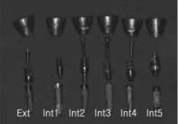
⑴ Implant, abutment and abutment screw The implants, abutments and abutment screws of six different implant systems were used. Regular and wide diameter implants of each system were se- lected(Fig. 1 and 2). Implants and abutments selected were presented in TableⅠ. Of the first implant de- sign, Avana Self Tapping Implant�(Osstem Co., Ltd., Seoul, Korea), “Ext(R)”was a 3.75㎜×13㎜ and
“Ext(W)”was a 5.0㎜×13㎜ implant with an external hex-butt joint. The hexed cemented abutments and titanium screws were used. Of the second implant design, SS-Ⅱ�(Osstem Co., Ltd., Seoul, Korea),
“Int1(R)”was a 4.1㎜×13㎜ and “Int1(W)”was a 4.8
㎜×13㎜ implant with an 8-degree Morse taper octa internal connection. The 1-piece solid abut-
ments were used. Of the third implant design, Camlog�(Altatec Biotechnologies, Irvine, CA, U.S.A.),
“Int2(R)”was a 3.8㎜×13㎜ and “Int2(W)”was a 5.0
㎜×13㎜ implant with an internal cylinder cam joint. The Standard�abutment and titanium screw were used. Of the fourth implant design, Implant- ium�(Dentium, Seoul, Korea), “Int3(R)”was a 3.8㎜
×12㎜ and “Int3(W)”was a 4.8㎜×12㎜ implant with an 11-degree taper with an internal hexagon con- nection. The 2-piece Dual�abutment and Standard� screw(titanium alloy) were used. Of the fifth implant
design, MIS�(MIS Implant Technologies Ltd., Israel),
“Int4(R)”was a 3.75㎜×13㎜ and “Int4(W)”was a 4.7㎜×13㎜ implant with an internal hexagonal joint. The 2-piece Anatomic Cementing transgingival
�abutment and titanium screw were used. Of the sixth implant design, Tapered Screw-Vent� (Centerpulse Dental Inc., Carlsbad, CA, U.S.A.),
“Int5(R)”was a 3.7㎜×13㎜ and “Int5(W)”was a 4.7
㎜×13㎜ implant with 1.5㎜ deep internal hexagon and a 1-degree taper joint. The 2-piece cemented Hex- Lock�abutment and titanium screw were used.
Fig. 1. Regular diameter implants, abutments, abutment screws and titanium crowns.
Fig. 2. Wide diameter implants, abutments, abutment screws and titanium crowns.
Table I. List of Components
Group Brand name Types of cemented abutments
Ext (R ) Avana Self Tapping Implant� hexed, collar 1㎜, height 5.5㎜
Ext (W) hexed, collar 1㎜, height 5.5㎜
Int1(R ) SS-Ⅱ� non-octa, height 5.5㎜
Int1(W) non-octa, height 5.5㎜
Int2(R ) Camlog� tricam, gingival collar 1.5㎜
Int2(W) tricam, gingival collar 1.5㎜
Int3(R ) Implantium� non-hex, gingival collar 1.0㎜
Int3(W) non-hex, gingival collar 1.0㎜
Int4(R ) MIS� hexed, gingival collar 2.0㎜
Int4(W) hexed, gingival collar 2.0㎜
Int5(R ) Tapered Screw Vent� hexed, 5.5㎜ wide profile
Int5(W) hexed, 6.5㎜ wide profile
Ext : external, Int : internal
⑵ Titanium CAD/CAM custom crown To compensate for the different abutment height and width of each implant system, titanium custom crowns of the same diameter(10㎜) and height(8㎜) were fabricated by means of CAD/CAM tech- nique(DCS, Austenal, Inc.,York, PA, U.S.A.). The abut- ment screw holes were formed at the center of the crowns to measure the detorque values after cyclic loading, with exception for the solid abutment of the Int1 group.
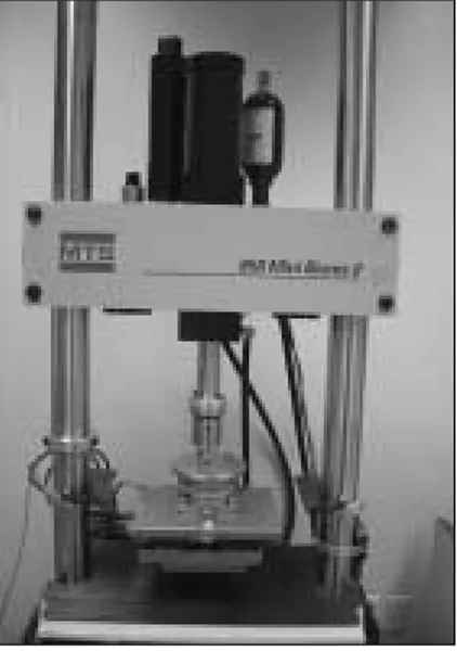
⑶ Loading machine(Fig. 3)
The Mini BionixⅡ Test System (MTS; MTS systems corp., Eden Prairie, Minn., U.S.A.) was used under constant temperature (18℃) and humidity(38%).
⑷ Customized jig(Fig. 4)
The jig was customized by the ISO standard35so that the force could be applied to the titanium crown at 30 degrees off-axis to produce a clinically severe single tooth bending force or cantilever load.
⑸ Torque gauge(Fig. 5)
Torque values and detorque values were measured by a digital torque gauge (MGT12, MARK-10 corp., Copiague, NY, U.S.A.), the details of which were as follows; the maximum measurement was 135N㎝, the scale was 0.1N㎝ and the measurement error was 0.5%.
METHODS
⑴ Tightening torque
Abutments were retained with titanium abut- ment screws tightened to 32N㎝ with digital torque gauge.
Fig. 3. Loading machine.
Fig. 4.Customized jig. Fig. 5. Digital torque gauge.
⑵ Initial detorque value
Initial detorque values were measured 10 minutes after tightening by a digital torque gauge. Identical tests were repeated five times for each.
⑶ Temporary cementation of the titanium crown After temporary filling of screw hole with cotton and Caviton�(GC corp., Tokyo, Japan), titanium custom crown was cemented temporarily with Cavitec�(Kerr, Romulus, MI, U.S.A.).
⑷ Detorque value after cyclic loading
Each test assembly (implant, abutment, abut- ment screw and crown) was mounted on the cus- tomized jig in the MTS loading machine. A testing device delivered dynamic sine curved loading forces between 20 and 320N at 14Hz for one million cycles(Fig. 6), or the approximate equivalent of 1 year mastication.36,37After cyclic loading, the detorque val- ues were measured by digital torque gauge. Identical tests were repeated five times for each group.
⑸ Statistical Analysis
SPSS statistical Software for Windows(rele-ase 12.0, SPSS Inc., Chicago, IL, U.S.A.) was used for sta- tistical analysis. One-way ANOVA and the Scheffe’s multiple range test were used for the comparison of
those different implant-abutment connections. And Mann-Whitney U test was used for statistical com- parison of the detorque values between the regular diameter implants and the wide ones, as well as the detorque values before and after cyclic loading.
All tests were performed at a 5% significance level.
RESULTS
The measured raw data, mean values, standard de- viations and loosening torque rates were presented in Table Ⅱ through Ⅴ. For all specimens, no dece- mentation or screw loosening was noticed by tactile or visual inspection during or at the completion of loading.
Initial detorque values of the regular diameter im- plants were shown in TableⅡ. The Int1 group showed the highest detorque value of 28.5N㎝.
The other groups were shown in the following de- creasing order: Int2; 28.2N㎝, Int4; 27.5N㎝, Int3;
27.4N㎝, Ext; 26.1N㎝, and Int5; 25.8N㎝.
One-way ANOVA indicated no significant dif- ference among groups.
Initial detorque values of the wide diameter im- plant groups were presented in TableⅢ. The Int1 group showed the highest mean value of 32.2N㎝, followed by: Int2; 31.1N㎝, Int4; 29.6N㎝, Ext; 29.5N
㎝, Int3; 29.2N㎝ and Int5; 28.9N㎝. One-way ANO- VA indicated a statistically significant differ- ence(P=0.046) among the some groups, however, pair- wise multiple comparison test using the Scheffe’s test indicated no significant difference.
Detorque values of the regular diameter implant groups after cyclic loading were presented in Table
Ⅳ. The Int1 group showed the highest mean value of 35.9N㎝. The other groups in decreasing order were as follows: Int2; 31.1N㎝, Int4; 29.6N㎝, Ext; 29.5N
㎝, Int3; 29.2N㎝, and Int5; 28.9N㎝. One-way ANOVA indicated a statistically significant differ- ence(P<0.001). Pairwise multiple comparison tests using Scheffe’s tests were carried out on mean Fig. 6. Loading pattern.
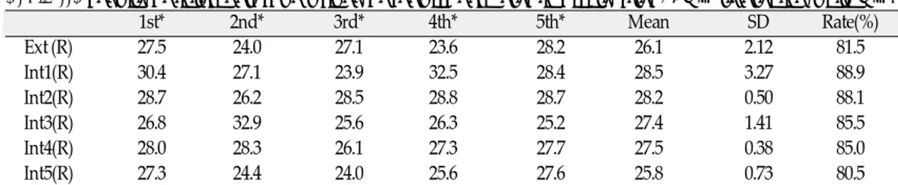
Table II. Results of initial detorque values of regular diameter implants after 32N㎝ tightening(unit: N㎝)
1st* 2nd* 3rd* 4th* 5th* Mean SD Rate(%)
Ext (R) 27.5 24.0 27.1 23.6 28.2 26.1 2.12 81.5
Int1(R) 30.4 27.1 23.9 32.5 28.4 28.5 3.27 88.9
Int2(R) 28.7 26.2 28.5 28.8 28.7 28.2 0.50 88.1
Int3(R) 26.8 32.9 25.6 26.3 25.2 27.4 1.41 85.5
Int4(R) 28.0 28.3 26.1 27.3 27.7 27.5 0.38 85.0
Int5(R) 27.3 24.4 24.0 25.6 27.6 25.8 0.73 80.5
*1st, 2nd, 3rd, 4th, 5th: the number of measurement times
Table III. Results of initial detorque values of wide diameter implants after 32N㎝ tightening(unit: N㎝)
1st* 2nd* 3rd* 4th* 5th* Mean SD Rate(%)
Ext (W) 29.3 29.4 30.3 28.1 30.2 29.5 0.88 92.1
Int1(W) 33.8 34.8 30.6 30.3 31.7 32.2 1.98 100.8
Int2(W) 31.7 32.2 32.8 27.0 31.6 31.1 2.32 97.1
Int3(W) 29.6 29.8 28.7 31.8 26.3 29.2 2.00 91.4
Int4(W) 28.0 29.3 31.3 30.0 29.6 29.6 1.19 92.6
Int5(W) 28.5 30.6 26.0 30.2 29.0 28.9 1.81 90.2
*1st, 2nd, 3rd, 4th, 5th: the number of measurement times
Table IV. Results of detorque values of regular diameter implants after cyclic loading(unit: N㎝)
1st* 2nd* 3rd* 4th* 5th* Mean SD Rate(%)
Ext (R) 19.2 23.4 22.0 19.0 21.9 21.1 1.92 66.0
Int1(R) 27.8 36.0 39.9 39.2 36.5 35.9 4.82 112.2
Int2(R) 24.9 24.2 24.6 24.7 24.6 24.6 0.25 76.9
Int3(R) 21.2 22.7 24.4 24.0 25.0 23.5 1.52 73.1
Int4(R) 26.1 25.7 23.7 22.0 25.4 24.6 1.70 76.8
Int5(R) 24.2 22.2 25.5 24.8 23.5 24.0 1.27 75.2
*1st, 2nd, 3rd, 4th, 5th: the number of measurement times
Table V. Results of detorque values of wide diameter implants after cyclic loading(unit: N㎝)
1st* 2nd* 3rd* 4th* 5th* Mean SD Rate(%)
Ext (W) 25.4 24.9 21.6 22.8 22.8 23.5 1.59 73.5
Int1(W) 38.7 39.0 37.7 42.0 42.0 39.9 1.99 124.7
Int2(W) 28.8 26.6 22.9 25.0 26.0 25.9 2.16 80.9
Int3(W) 22.0 20.6 24.0 23.2 22.7 22.5 1.29 70.3
Int4(W) 24.5 26.4 27.5 27.9 27.8 26.8 1.43 83.8
Int5(W) 22.9 25.2 17.7 15.2 20.2 20.2 3.99 63.3
*1st, 2nd, 3rd, 4th, 5th: the number of measurement times
detorque values(α=0.05). The detorque value of the Int1(R) group was significantly higher than any other groups, which showed no significant difference among them.
Detorque values of the wide diameter implant groups after cyclic loading were presented in Table
Ⅴ. Here again, the Int1(W) group had the highest mean detorque value of 39.9N㎝. The decreasing or- der were as follows: Int2; 24.6N㎝, Int4; 24.6N㎝, Int5;
24.0N㎝, Int3; 23.5N㎝, and Ext; 21.1N㎝. One-way ANOVA indicated a significant difference(P<0.001) among these groups. Pairwise multiple comparison tests using Scheffe’s test indicated that the Int1 group was significantly higher than the others,
while the Int5 group was significantly lower than the Int1, the Int2 and the Int4(P<0.05).
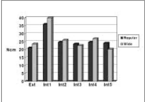
Mean initial detorque values of the regular and the wide diameter implant groups were illustrated in Fig.
7. The wide diameter implants showed higher ini- tial detorque values than the regular ones in all groups. However, only the Ext, the Int4 and the Int5 groups were significantly different(p<0.05) as ac- cording to Mann-Whitney U test.
The Mean detorque values after cyclic loading of the regular and the wide implants were illustrated in Fig. 8. All the wide diameter implant groups exhibited higher detorque values, except for the Int3 and the Int5 group. Mann-Whitney U test re-
Fig. 7.Mean initial detorque values. Fig. 8.Mean detorque values after cyclic loading.
Fig. 9. Mean detorque values of regular diameter implants. Fig. 10. Mean detorque values of wide diameter implants.
vealed that only the Int4 group was significantly dif- ferent(p<0.05).
The Mean initial detorque values of the regular di- ameter implants were compared with the mean detorque values after cyclic loading in Fig. 9. The Int1 group showed an increase in the detorque value af- ter cyclic loading, while the others showed de- creasing tendency in the detorque values. All groups were significantly different, except for the Int5 group(p<0.05).
The mean initial detorque values of the wide di- ameter implants were compared with the mean detorque values after cyclic loading in Fig. 10.
Again, the Int1 group showed an increase in the detorque value after cyclic loading, while the others showed a decrease. Mann-Whitney U test demon- strated statistically significant differences in all groups(p<0.05).
DISCUSSION
Together with proper design of the occlusion and stable osseointegration, a reliable connection be- tween implant and abutment is an important pre- condition for the appropriate functioning and sta- bility of implant restorations,17especially cemented ones.38Several clinical studies report widely varying incidences of abutment loosening for different types of abutment connections. In particular, external hex configurations seem to be prone to abutment screw loosening.
Short, narrow external geometry is particularly vul- nerable to screw loosening because of the limited en- gagement of its external member and the presence of a short fulcrum point when tipping forces are ap- plied.39,40
To overcome some of the inherent design limi- tations of the external hexagonal connection, a va- riety of alternative connections have been developed.41 The most notables are the cone screw, the cone hex, the internal octagonal, the internal hexagonal, the
cylinder hex, the Morse taper, the spline, the inter- nal spline, and the resilient connection. Of these, the internal octagonal connection and the resilient con- nection are no longer available. Internal interface de- signs offer a reduced vertical height for restora- tive components; distribution of lateral loading deep within the implant; a shielded abutment screw; long internal wall engagements that create a stiff, unified body that resists joint opening; wall en- gagement with the implant that buffers vibration; the potential for a microbial seal; extensive flexibility; and the ability to lower the restorative interface to the im- plant level esthetically.41
In this study, the external hexagonal connection was compared with five other different internal con- nections. The initial detorque values showed no statistical differences among the different connections.
But, the 8-degree Morse taper octa internal con- nection, the SS-Ⅱ, recorded the highest values for both regular and wide diameter implants. Moreover, the SS-Ⅱ showed a mean 32.2N㎝ detorque value, at a 100.8% loosening rate. It may be the result of a cold welding which can be defined as an increase in loosening torque with respect to tightening torque.
Sutter et al42demonstrated that the loosening torque of ITI 8-degree Morse taper design was 124% of the tightening torque at a clinically relevant level of 25 N㎝, however, little information was given as to the nature of the apparatus used to record this da- ta. Norton43evaluated the loosening torque, with re- spect to a range of tightening torques, both at a low torques ranging from 4 to 50 N㎝, and high torques ranging from 100 to 300 N㎝. He conclud- ed that cold welding was only apparent in the high torque series where tightening torques of 100 N㎝
or more were being applied as well as the Astra 4.0
㎜ and the ITI units. For clinically relevant levels of tightening torque (20 to 40N㎝), the loosening torque was approximately 80% to 85% for all units tested, and cold welding did not occur. Also, he pos- tulated that the only factor that seemed to influence
resistance to loosening was surface area of interface, whereby increased surface area resulted in in- creased resistance, most likely due to the effect of in- creased resting friction. In this study, the loosening torque of the 4.1㎜ diameter 8-degree Morse taper octa internal connection implant was 88.9%, but the wide designed implant showed 100.8% loosening torque. In other words, cold welding was thought to have occurred. This could be accounted for by the increased surface area of wide implant. In spite of, the integration of the internal octagon to an 8-degree Morse taper connection, it can be concluded that cold welding could occur in the wide 8-degree Morse ta- per octa internal connection implant with consequent slight loss of contact surface area.
The Camlog and the MIS implant systems showed the next highest detorque values. These could be ac- counted for the advantages of deep internal con- nection and larger contact surface area. But, the Tapered Screw Vent, internal hex with a 1-degree ta- per connection, recorded the lowest initial detorque value. Interestingly, after the abutment screw was loosened, the Hex-Lock abutment could not be separated from the implant by hand pressure. It seemed that cold welding could occur in the 1-de- gree taper mating surface, even though, the abutment screw could be loosened irrelevant to cold welding, when the 2-piece abutment was used. This is because the frictional force of the taper joint could not con- tribute to the resistance to screw loosening. The Implantium showed a comparatively low initial detorque value, despite 11-degrees taper joint. It al- so might be attributed to 2-piece abutment without hexagon.
After dynamic cyclic loading, the detorque val- ues of different implant systems showed statistically significant differences(p<0.001). The SS-Ⅱ record- ed the highest detorque values in both regular and wide diameter implants with statistically significant differences, having shown higher values than when cyclic loading was not exerted.
Merz et al44explained the differences between the butt joint and the taper joint, that is, the external hex configuration and the taper connection em- ployed quite different mechanical principle of func- tion. In the external hex configuration, the axial preload of the abutment screw is a determining factor for stability of the connection.45,46This screw alone secures the abutment, for example, under horizontal loading. There is no lock form or positive locking by the external hex, which determines the ro- tational position but does not absorb any lateral loading. Therefore pure clamping is the underlying principle. The optimal preload corresponds theo- retically to the yield point of the screw. The aim of tightening is to achieve the optimum preload that will maximize the fatigue life, while offering a rea- sonable degree of protection against loosening. In practice, the achievable preload is limited by the su- per-position of additional tension, related to the external loading. For instance, Haack et al10report- ed a preload of 60% or yield strength for gold alloy screws when torqued to the recommended 32N㎝.
In a taper connection, lock form and friction are the basic principles. Lateral loading is related main- ly by the taper interface, which prevents the abut- ment from tilting off, even when the connection between the taper section and the thread of the abutment is lost. The same mechanism, referred to as positive or geometry locking, is responsible for protecting the abutment threads from excessive functional load. There is no possibility of tilting about a single point or small area, as with an external hex. The longitudinal preload is limited to about 45 to 55N, but because of the tapered design, a high nor- mal pressure is maintained in the contact area, granting stable retention of position by frictional forces. With the low axial preload, the danger of reach- ing the yield load by superimposing external loads is highly limited.
Sutter et al40demonstrated under dynamic load, the loosening torque of the ITI was seen to be on av-
erage 107% of the tightening torque, though de- tailed information about the test was limited. In our study, both regular and wide SS-Ⅱ implant showed higher detorque values than tightening torque, even higher than initial detorque values. We could explain a part of it with reference from a previous finite element analysis(FEA) study. In the previous FEA study,44ITI implant, with 1-piece solid abutment and steel ball, were used, and a 30-degree off-axis force was applied. Similarly, in this experiment, 30-degree off-axis force was applied to SS-Ⅱ implant and 1-piece solid abutment with a tem- porarily cemented titanium crown. On the side facing the external load, the implant and the abut- ment might experience tensional stress from bend- ing, while on the opposite side the connection might be subjected to compression. The majority of the load transfer from the abutment to the implant presumed to take place through the taper connection.
The screw threads, however, was subjected to a very limited stress in the tapered connection. Thread portion of the abutment supposed to be protected to a greater extent by the taper connection. Maximal tension stress was experienced at the thread root on the tension side, however the area where this applies was extremely limited, so that the supporting effects related to the small size of the stress area exert a pos- itive influence and grant the survival of the restora- tion against the cyclic loading of 20 N㎝ to 320 N㎝.
The majority of the off-axis force might promote more compression than tension in the taper joint in this test condition, which favored cold welding. More stud- ies are needed on the effects of the factors of this test condition, such as the amount of load applied, the location or direction of force application, and the du- ration of the loading period. It might be postulated that such high forces being absorbed by the conical joint without detectable deformation is undesir- able, since this might lead to transfer of these forces to the bone-to-implant interface resulting in overload and bone resorption or implant failure. However da-
ta on marginal bone integrity around functioning im- plants of this type would not support this view.47-51 The Camlog and the MIS implant with deep in- ternal connection demonstrated the next highest detorque values after cyclic loading. Camlog has a 5.5㎜ deep cylinder that engages the internal walls of the implant, three lateral cam projections that pro- vide indexing and antirotation, and an abutment screw projecting 2㎜ beyond the cylinder. MIS has the slip-fit, internal-cylinder hex interface that extends 2㎜ into the implant, and 3㎜ abut-ment screw pro- jection. When external force is applied, the internally connected abutment exerts lateral force to the internal wall of the implant, contrary to the external hex con- nection where tensile force is concentrated on the abutment screw. The longer the internal lever arm, the less force is transferred to the internal wall, and the more evenly the force is distributed.
Therefore, the abutment screw is subject to little force, and screw loosening decrease in the internal con- nection like those of the Camlog and the MIS implant.
The wide diameter Tapered Screw Vent implant demonstrated lower detorque values after cyclic loading than the SS-Ⅱ, the Camlog and the MIS im- plant with statistical significance. But, like initial detorque value measurements, in the Tapered Screw Vent implant, Hex-Lock abutment could not be separated from the implant by hand pressure af- ter abutment screw loosening. It also seemed that cold welding can occur in the 1-degree taper mating surface, even after the abutment screw loosening in the 2-piece abutment system. It was interesting that there was significant difference between the wide diameter MIS and the Tapered Screw Vent, even though, both have similar joint design, except for the 1-degree taper. The Tapered Screw Vent that had the taper hex design showed rapid decrease in the detorque value after repeated tightening, cyclic loading and loosening. Future study should in- clude more sample sizes to compare these two joint designs.
Implantium with an 11-degree tapered connection showed no cold welding, because of the non-hex, 2- piece abutment which lacks the antirotational re- sistance.
A wide platform increases abutment stability by reducing the occlusal table to loading platform cantilever and the concomitant stress to the abutment screw.52In this study, the wide diameter implant groups showed higher detorque values except for im- plantium and Tapered Screw Vent after cyclic load- ing. It could be proposed that an implant with a wide diameter implant-abutment interface experiences less abutment screw loosening than that of regular di- ameter implant-abutment interface when subject- ed to masticatory-like forces. When an implant prosthesis is subjected to a masticatory-like force(an off-axis bending force), the force transmitted to the interface between abutment and implant body is dis- tributed over a larger surface area. Plastic defor- mations at the interface of the implant and the abutment are less likely to occur with the wide di- ameter implant than with regular one. Thus, with less plastic deformation on the implant-abutment interface, there is less screw deformation and less micromo- tion at the level of the abutment screw thread-implant body interface.33 Regular and wide diameter Implantium have the same implant-abutment con- tact area and use an identical abutment screw.
Also, the abutment does not contact the platform sur- face of the implant. Therefore, the use of wide im- plant did not increase the detorque value. The wide Tapered Screw Vent showed rapid decrease in the detorque value after repeated use, as stated above.
It would have been preferable to have changed the titanium crowns, abutment screws and sets of im- plants after each test. Clinically, however, this study could be considered significant when the screw was repeatedly tightened and loosened, but the results of this specific test revealed low standard deviation.
Clinically, the occlusal forces are distributed over
the prosthesis, complex in vector and magnitude, and remaining teeth and cyclical forces vary in intensi- ty. But in vitro study, the load was applied on a sin- gle implant crown with high-magnitude and criti- cal vector for a considerably long duration of time.
In addition to joint designs, actual preload achieved in the components was dependent on the finish of the interfaces, friction between components, geom- etry, and material properties. Even within the same lot of prosthetic components, there may be signifi- cant differences in the preload achieved because of the factors listed above.45But in this study, we focused solely on joint design, and did not consider those fac- tors. Considering these limitations, investigations with more realistic loading conditions and more sample sizes would be necessary.
CONCLUSIONS
Within the limitations of this study, the following conclusions were drawn:
1. The initial detorque values of six different implant- abutment connections were not significantly dif- ferent(p>0.05).
2. The detorque values after one million dynamic cyclic loading were significantly different (p<0.05).
3. The SS-Ⅱ regular and wide implant both record- ed the higher detorque values than other groups after cyclic loading(p<0.05).
4. Of the wide implants, the initial detorque values of Avana Self Tapping Implant, MIS and Tapered Screw Vent, and the detorque values of MIS im- plant after cyclic loading were higher than their regular counterparts(p<0.05).
5. After cyclic loading, SS-Ⅱ regular and wide im- plants showed higher detorque values than before(p<0.05).
※ I acknowledge Seoul national university's financial support for the new faculty.
REFERENCES
1. Adell R, Lekholm U, Bra�nemark PI. A 15-year study of osseointegrated implants in the treat- ment of the edentulous jaw. Int J Oral Surg 1981;10:387-416.
2. Cox JF, Zarb GA. The longitudinal clinical effica- cy of osseointegrated dental implants: A 3-year re- port. Int J Oral Maxillofac Implants 1987;2:91-100.
3. Adell R, Eriksson B, Lekholm U, Bra�nemark PI, Jemt T. A long-term follow-up of osseointegrated im- plants in the treatment of totally edentulous jaws.
Int J Oral Maxillofac Implants 1990;5:347-59.
4. Zarb GA, Schmitt A. The longitudinal clinical ef- fectiveness of osseointegrated implants: The Toronto study. PartⅢ. Problems and complications encountered. J Prosthet Dent 1990;64:185-94.
5. Binon PP. The effect of implant/abutment hexag- onal misfit on screw joint stability. Int J Prosthodont 1996;9:149-60.
6. Jemt T. Failures and complications in 391 con- secutively inserted fixed prostheses supported by Bra�nemark implants in edentulous jaws: A study of treatment from the time of prosthesis placement to the first annual checkup. Int J Oral Maxillofac Implants 1991;6:270-6.
7. Jemt T. Multicenter study of overdentures supported by Bra�nemark. Int J Oral Maxillofac Implants 1992;7:513-22.
8. Jemt T, Linden B, Lekholm U. Failures and com- plications in 127 consecutively inserted fixed pros- theses supported by Bra�nemark implants: From prostheses treatment to first annual check up. Int J Oral Maxillofac Implants 1992;7:40-3.
9. McGlumphy EA, Mendel DA, Hollowa JA. Implant screw mechanics. Dent Clin North Am 1998;42:71- 89.
10. Haack JE, Sakaguchi RL, Coeffy JP. Elongation and preload stress in dental implant abutment screws. Int J Oral Maxillofac Implants 1995;10:529- 36.
11. Lang JA, May KB, Wang RF. The effect of the use of a countertorque device on the abutment-implant complex. J Prosthet Dent 1999;81:411-7.
12. Artzi Z, Dreiangel A. A screw lock for single- tooth implant superstructures. J Am Dent Assoc 1999;130:677-82.
13. Schwarz MS. Mechanical complications of dental implants. Clin Oral Impl Res 2000;11 Suppl 1:156- 8. Review.
14. Cavazos E, Bell FA. Preventing loosening of implant abutment screws. J Prosthet Dent 1996;75:566-9.
15. Jorneus L, Jemt T, Carlsson L. Loads and designs of screw joints for single crowns supported by os- seointegrated implants. Int J Oral Maxillofac Implants 1992;7:353-9.
16. Graves SL, Jansen CE, Siddique AA, Beauty KD.
Wide diameter implants: indications, considerations
and preliminary results over a two-year period. Aust Prost- hodont J 1994;8:31-7.
17. Norton MR. An in vitro evaluation of the strength of an internal conical interface compared to a butt joint design. Clin Oral Impl Res 1997;8:290-8.
18. Binon PP. Implants and components. Int J Oral Maxillofac Implants 2000;15:633-45.
19. Merz BR, Hunenbart S, Belser UC. Mechanics of the implant-abutment connection: an 8-degree taper compared to a butt joint connection. Int J Oral Maxillofac Implants 2000;15:519-26.
20. Binon PP. Evaluation of machining accuracy and consistency of selected implants, standard abut- ments, and laboratory analogs. Int J Prosthodont 1995;8:162-78.
21. Barzilay I. The search for intimacy: Rotational ac- curacy of implant components for single-tooth, root- form implants. Dent Implantol Update 1991;2:5-7.
22. Fenton AH, Zarb GA. Research status of prostho- dontic procedures. Int J Prosthodont 1993;6:137-44.
23. Jemt T. Modified single and short span restorations supported by osseointegrated fixtures in the par- tially edentulous jaw. J Prosthet Dent 1986;55:243- 7.
24. Kallus T, Bessing C. Loose gold screws frequent- ly occur in full arch fixed prostheses supported by osseointegrated implants after 5 years. Int J Oral Maxillofac Implants 1994;9:169-78.
25. Jemt T, Laney WR, Harris D, Henry PJ, Krogh PHJ Jr, Polizzi G, et al. Osseointegrated implants for single tooth replacement: A 1-year report from a multicenter prospective study. Int J Oral Maxillofac Implants 1991;6:29-36.
26. Becker W, Becker BE. Replacement of maxillary and mandibular molars with single endosseous implant restorations: A retrospective study. J Prosthet Dent 1995; 74:51-5.
27. Eckert SE, Wollan PC. Retrospective review of 1170 endosseous implants placed in partially edentulous jaws. J Prosthet Dent 1998;79:415-21.
28. Niznick GA. The implant abutment connection: The key to prosthetic success. Compend Contin Educ Dent 1991;12: 932-7.
29. Schroeder A, Sutter F, Krekeler G. Oral Implantology. General principles and hollow cylinder system. Stuttgart: Thieme, 1998.
30. Schulte W, d’Hoedt B, Axmann D, Gomez G.
The first 15 years of the Tu¨ebingen implant and its further development to the Frialit-2 system. Z Zahnarztl Implantol 1992;8:3-22.
31. Arvidson K, Bystedt H, Ericsson I. Histometric and ultrastructural studies of tissues surrounding Astra dental implants in dogs. Int J Oral Maxillofac Implants 1990;5:127-34.
32. Binon PP. The Spline implant: Design, engineer- ing, and evaluation. Int J Prosthodont 1996;9:419- 33.
33. Hoyer SA, Stanford CM, Buranadham S, Fridrich
T, Wagner J, Gratton D. Dynamic fatigue proper- ties of the dental implant-abutment interface:
Joint opening in wide- diameter versus standard- diameter hex-type implants. J Prosthet Dent 2001;
85:599-607.
34. Mollersten L, Lockowandt P, Linden LA.
Comparison of strength and failure mode of sev- en implant system: An in vitro test. J Prosthet Dent 1997;78:582-91.
35. ISO/DIS 14801 Dental implants-Dynamic con- tinuous fatigue test. International Organization for Standardization, 2001.
36. Binon PP, McHugh MJ. The effect of eliminating im- plant/abutment rotational misfit on screw joint sta- bility. Int J Prost- hodont 1996;9:511-9.
37. Wiskott HW, Nicholls JI, Belser UC. Stress fa- tigue: basic principles and prosthodontic impli- cations. Int J Prosthodont 1995;8:105-16.
38. Felton DA. Cemented versus screw-retained implant prostheses: Which is better? [current issues fo- rum]. Int J Oral Maxillofac Implants 1999;14:138- 9.
39. Weinberg LA. The biomechanics of force distri- bution in implant-supported prostheses. Int J Oral Maxillofac Implants 1993;8:19-31.
40. Weinberg LA, Kruger B. A comparison of im- plant-prosthesis loading with four clinical variables.
Int J Prosthodont 1995; 8:421-33.
41. Binon PP. Implants and components: Entering the new millenium. Int J Oral Maxillofac Implants 2000;15:76-94.
42. Sutter F, Weber HP, Sorensen J, Belser U. The new restorative concept of the ITI dental implant sys- tem: design and engineering. Int J Periodont Rest Dent 1993;13:409-31.
43. Norton MR. Assessment of cold welding proper- ties of the internal conical interface of two com- mercially available implant systems. J Prosthet Dent 1999;81:159-66.
44. Merz BR, Hunenbart S, Belser UC. Mechanics of the implant-abutment connection: an 8-degree taper
compared to a butt joint connection. Int J Oral Maxillofac Implants 2000;15:519-26.
45. Sakaguchi RL, Borgersen SE. Nonlinear contact analysis of preload in dental implant screws. Int J Oral Maxillofac Implants 1995;10:295-302.
46. Burguete RL, Johns RB, King T, Patterson EA.
Tightening characteristics for screwed joints in osseointegrated dental implants. J Prosthet Dent 1994;71:592-9.
47. Arvidson K, Bystedt H, Frykholm A, von Konow L, Lothigus E. A 3-year clinical study of Astra dental implants in the treatment of edentulous mandibles. Int J Oral Maxillofac Implants 1992;7:321- 9.
48. Arvidson K, Bystedt H, Frykholm A, von Konow L, Lothigus E. Five year prospective follow-up report of the Astra Tech Dental Implant System in the treatment of edentulous mandibles. Clin Oral Impl Res 1998;9:225-34.
49. Makkonen TA, Holmberg S, Nieme L, Olsson C, Tammisalo T, Peltola J. A 5-year prospective clin- ical study of Astra Tech dental implants sup- porting fixed bridges or overdentures in the eden- tulous mandible. Clin Oral Impl Res 1997;8:469-75.
50. Norton M. Marginal bone levels at single tooth im- plants with a conical fixture design. The influ- ence of surface macro- and microstructure. Clin Oral Impl Res 1998;9:91-9.
51. Palmer RM, Smith BJ, Palmer PJ, Floyd PD. A prospective study of Astra single tooth implants.
Clin Oral Impl Res 1997; 8:173-9.
52. Jarvis W. Biomechanical advantages of wide di- ameter implants. Compend Contin Educ Dent 1997;18:687-94.
Reprint request to:
KYUNG-SOOJANG D.D.S., M.S.D., Ph.D.
DEPARTMENT OFPROSTHODONTICS,COLLEGE OFDENTISTRY,SEOUL NATIONALUNIVERSITY,
28-1, YEONGUN-DONG,CHONGNO-GU,SEOUL,110-749, KOREA [email protected]