Influence of the implant abutment types and the dynamic loading on initial screw loosening
Eun-Sook Kim, DDS, MS, Soo-Yeon Shin*, DDS, MS, PhD
Department of Prosthodontics, College of Dentistry, Dankook University, Cheonan, Republic of Korea
PURPOSE. This study examined the effects of the abutment types and dynamic loading on the stability of implant prostheses with three types of implant abutments prepared using different fabrication methods by measuring removal torque both before and after dynamic loading. MATERIALS AND METHODS. Three groups of abutments were produced using different types of fabrication methods; stock abutment, gold cast abutment, and CAD/CAM custom abutment. A customized jig was fabricated to apply the load at 30° to the long axis. The implant fixtures were fixed to the jig, and connected to the abutments with a 30 Ncm tightening torque. A sine curved dynamic load was applied for 105 cycles between 25 and 250 N at 14 Hz. Removal torque before loading and after loading were evaluated. The SPSS was used for statistical analysis of the results. A Kruskal-Wallis test was performed to compare screw loosening between the abutment systems. A Wilcoxon signed-rank test was performed to compare screw loosening between before and after loading in each group (α=0.05). RESULTS.
Removal torque value before loading and after loading was the highest in stock abutment, which was then followed by gold cast abutment and CAD/CAM custom abutment, but there were no significant differences.
CONCLUSION. The abutment types did not have a significant influence on short term screw loosening. On the other hand, after 105 cycles dynamic loading, CAD/CAM custom abutment affected the initial screw loosening, but stock abutment and gold cast abutment did not. [J Adv Prosthodont 2013;5:21-8]
KEY WORDS: Computer-aided design; Dental implantation; Prosthesis failure; Removal torque; Screw loosening
INTRODUCTION
As the efficiency and clinical success of osseointegration have been reported, implants have become a common treatment for missing tooth. This is because a single implant had an advantage in reconstructing the tooth form and function of missing part without preparation of the adjacent teeth.1,2
Corresponding author:
Soo-Yeon Shin
Department of Prosthodontics, College of Dentistry, Dankook University, 119, Dandae-ro, Dongnam-gu, Cheonan-si, Chungcheongnam-do, 330-714, Republic of Korea
Tel. 82415500253: e-mail, [email protected]
Received June 25, 2012 / Last Revision October 22, 2012 / Accepted November 19, 2012
© 2013 The Korean Academy of Prosthodontics
This is an Open Access article distributed under the terms of the Creative Commons Attribution Non-Commercial License (http://creativecommons.
org/licenses/by-nc/3.0) which permits unrestricted non-commercial use, distribution, and reproduction in any medium, provided the original work is properly cited.
Despite the high clinical success of the implant, Laney et al.3 reported several complications after 3-year follow up research of a single-implant prostheses. The complica- tions were an abutment screw fracture, soft tissue pene- tration, mucosal inflammation and screw loosening. The most common complication was abutment screw loosen- ing.4,5
The reasons for screw loosening are fatigue, inade- quate tightening torque, settling effect, vibrating micro- movement and excessive bending.6 Some authors7 report- ed that the main factor in screw loosening was an inap- propriate tightening torque. The aim of applying a tight- ening torque to the abutment screw was to make screw elongation and grant stability through a compressive force between the abutment system and fixture.8 If the tightening torque was not consistent, the following pre- load showed a difference and could affect the removal torque. The level of screw loosening could be measured by evaluating the screw elongation,9 preload using gauge,10 and removal torque of the screw.11
Implant abutments should be made from biocompati-
ble materials with adequate mechanical properties12 to ful- fill the biological, functional and esthetic demands.13 In addition, they should accurately and passively fit on their mating implants to prevent complications, such as screw loosening, bone loss and abutment fractures during func- tion. For the optimal mucogingival esthetics, implant abutments also require the appropriate emergence profile required to support the surrounding soft tissue.14
Implant abutments can be either stock or custom abutments, and there are two types of custom abutments:
gold cast and CAD/CAM custom abutments.15 In the past, stock and gold cast abutments were used typically but the application of CAD/CAM custom abutments has now increased in implant dentistry.
Some studies found the fit of CAD/CAM implant frameworks to be statistically superior to that of conven- tional cast frameworks.16-18 On the other hand, compara- tive research into the stability of CAD/CAM custom abutment, stock abutment and gold cast abutment are rare. This study examined the effects of the abutment types and dynamic loading on the stability of implant prostheses with three types of implant abutments pre- pared using different fabrication methods by measuring removal torque before and after dynamic loading.
MATERIALS AND METHODS
The implant fixtures and abutment screws selected in this study were GS II Fixture Ø4.0 × 11.5 mm (Osstem Co., Seoul, Korea) and EbonyGold Screw (Osstem Co., Seoul, Korea), respectively (Fig. 1). Twenty one implant fixtures
and abutment screws were used.
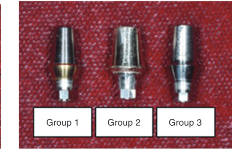
Three abutments fabricated in different processes were used: stock abutment (Group 1), gold cast abutment (Group 2), and CAD/CAM custom abutment (Group 3) (Fig. 2). Each group contained 7 specimens. The manu- facturer and composition of the abutments are shown in Table 1.
Three types of abutments were fabricated to a similar form with stock abutment for standardization. Transfer Abutment, which had a 4 mm diameter, 2 mm collar and 6 mm height (8 mm length), was selected as stock abut- ment (Group 1). To produce gold cast abutment (Group 2), a working model was made in the conventional meth- od: Transfer Abutment was connected to a lab analogue, and analogue was fixed with improved stone, and a 2 mm collar soft tissue was made. GoldCast Abutment was con- nected to the working model, a wax pattern was shaped as a 4 mm diameter and 8 mm length, and casting was fin- ished with type mm gold alloy. The fabrication of CAD/
CAM custom abutment (Group 3) was performed by scanning the model with an optic and touch scanner, designing with a CAD software, and milling a titanium block of 4 mm diameter and 8 mm length with an ultra- sonic milling machine.
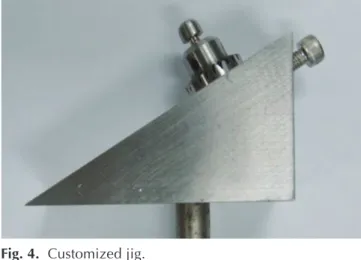
The customized jig was fabricated according to the ISO standard 14801 for dentistry-fatigue test for endosse- ous dental implants (Figs. 3 and 4). The jig was designed to apply a force to the abutment at 30° to the long axis.
The implant fixtures were fixed to the jig, and were connected to the abutments with a 30 Ncm tightening torque using an electronic torque controller iSD900
Table 1. Abutment systems used in this study
Group Abutment system N Composition Brand name & manufacturer
1 Stock abutment 7 Ti-6Al-4V Transfer abutment (Osstem Co., Seoul, Korea)
2 Gold cast abutment 7 type III gold alloy GoldCast abutment (Osstem Co., Seoul, Korea)
3 CAD/CAM custom abutment 7 Ti-6Al-4V MYPLANTTM (Raphabio, Seoul, Korea)
Fig. 1. Implant fixture and abutment screw.
Group 1 Group 2 Group 3
Fig. 2. Abutment.
(NSK, Tochigi-ken, Japan) (Fig. 5). After 10 minutes, the same tightening torque was applied to compensate for the loss of preload caused by surface settling of the interface.
Another 10 minutes later, the removal torque before load- ing was measured using a digital torque gauge HTG2- 200Nc (IMADA, Toyohashi, Japan) (Fig. 6).
The implant fixtures were fixed to the jig, and were connected to the abutments with a 30 Ncm tightening torque. The jig was installed in a dynamic loading fatigue
tester MTS 810 (Material Test Systems Co., Minnesota, USA) (Fig. 7). According to the ISO standard 14801, a cylindrical stainless steel metal cap was located on the abutment. A sine curved dynamic load was applied for 105 cycles between 25 and 250 N at 14 Hz. All dynamic load- ing fatigue tests were carried out at room temperature.
After dynamic loading removal torque was evaluated using the same digital torque gauge used to measure the removal torque before loading.
The ratio of removal torque before loading and tight- ening torque can be an indicator of how much loosening takes place before loading. The ratio of removal torque after loading and tightening torque can be an indicator of how much loosening occurs after loading. The ratio of removal torque before and after loading can be an indica- tor of the degree of loosening caused by the dynamic load.
30°
Fig. 3. Schematic diagram of the testing condition.
Fig. 4. Customized jig.
Fig. 5. Torque controller.
Fig. 6. Torque gauge.
Fig. 7. Fatigue tester.
Each loss rate of removal torque was calculated using following formula.
Loss ratio of removal torque before loading (%)
= Tightening torque – Removal torque before loading
× 100 Tightening torque
Loss ratio of removal torque after loading (%)
= Tightening torque – Removal torque after loading
× 100 Tightening torque
Loss ratio of removal torque between before and after loading (%)
= Removal torque before loading – Removal torque after loading
× 100 Removal torque before loading
The SPSS (Release 12.0, SPSS Inc., Chicago, IL, USA) was used for statistical analysis. A Kruskal-Wallis test was performed to compare screw loosening between abut- ment systems. A Wilcoxon signed-rank test was per- formed to compare the screw loosening between before and after loading in each group.
RESULTS
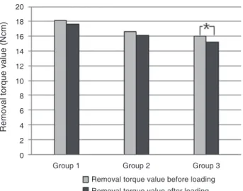
The mean values and standard deviations of removal torque value before loading and after loading were shown in Table 2: removal torque value before loading were 18.12 ± 2.11 Ncm in group 1, 16.63 ± 1.48 Ncm in Group 2, and 16.06 ± 2.45 Ncm in Group 3, respectively;
removal torque value after loading were 17.67 ± 2.60 Ncm in Group 1, 16.10 ± 1.56 Ncm in Group 2, and 15.20 ± 2.25 Ncm in group 3, respectively. Group 1 showed the highest removal torque value before loading followed in order by Group 2 and 3. Group 1 showed the highest removal torque value after loading followed in order by Group 2 and 3.
A Kruskal-Wallis test was performed for intergroup comparison of removal torque value before loading and after loading. Both removal torque value before loading and after loading did not show significant differences (Table 2).
A Wilcoxon Signed-Rank test was performed to com- pare removal torque value before and after loading in each group. There were no significant differences in Groups 1 and 2, but a significant difference was found in Group 3 (P<.05) (Table 3 and Fig. 8).
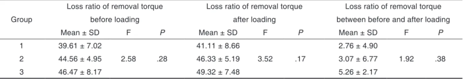
The mean values and standard deviations of loss ratio of removal torque before loading were 39.61 ± 7.02% in Group 1, 44.56 ± 4.95% in Group 2, and 46.47 ± 8.17%
in Group 3, respectively. Loss ratio of removal torque after loading were 41.11 ± 8.66% in Group 1, 46.33 ± 5.19% in Group 2, and 49.32 ± 7.48% in Group 3, respectively. Loss ratio of removal torque between before and after loading were 2.76 ± 4.90% in Group 1, 3.07 ± 6.77% in Group 2, and 5.26 ± 2.17% in Group 3, respec- tively (Table 4).
Table 2. Results of the Kruskal-Wallis test for removal torque value between abutment systems
Group Removal torque value before loading Removal torque value after loading
Mean ± SD F P Mean ± SD F P
1 18.12 ± 2.11 17.67 ± 2.60
2 16.63 ± 1.48 1.87 .18 16.10 ± 1.56 2.30 .13
3 16.06 ± 2.45 15.20 ± 2.25
Table 3. Results of the Wilcoxon Signed-Rank test for removal torque value before and after loading
Group T Df P
1 -1.52 2 .13
2 -1.19 2 .24
3 -2.37 2 .02*
*: significant at P<.05
Fig. 8. Comparison of removal torque value before and after loading.
*: significant at P<.05
20 18 16 14 12 10 8 6 4 2 0
Group 1 Group 2 Group 3
Removal torque value (Ncm)
Removal torque value before loading Removal torque value after loading
Group 1 showed the lowest loss ratio of removal torque before loading followed in order by Groups 2 and 3. Group 1 showed the lowest loss ratio of removal torque after loading followed in order by Groups 2 and 3.
Group 1 showed the lowest loss ratio of removal torque between before and after loading followed in order by Groups 2 and 3. The intergroup comparison of loss ratio of removal torque resulted in no significant differences (Table 4 and Fig. 9).
DISCUSSION
Implant abutments can be either stock, cast custom or CAD/CAM custom abutments. The primary advantage of stock abutments is their lower initial cost. On the oth- er hand, the ideal anatomic contour and emergence pro- file cannot be reproduced with stock abutments. Gold cast abutments are made specifically for the patient’s indi- vidual tooth that the corresponding implant replaces.
Therefore, the emergence profile is confluent from the implant to the abutment and to the superstructure.
Custom abutment can be configured precisely if correted angulation is required. The disadvantage of gold cast abutment is the high cost and complicated fabrication process in that investing, casting and finishing could be prone to manufacturing errors. CAD/CAM custom abut- ment has the potential advantages of both stock and gold cast abutments; esthetic emergence profile, ideal anatomic contour, and angulation correction. In addition, CAD/
CAM abutment is cheaper than gold cast abutment.19 A number of critical factors including the implant abutment connection, characteristics of the abutment screw, adequate preload by proper tightening torque, and the precision of the attachment of the mating implant components are important in the screw joint stability.20
An implant abutment connection has a great impact on screw loosening. Screw loosening occurs on the slip joint of the external hex in the external connection type by vibration and micro-movement during functional load- ing.21,22 It appears that the external connection type is par- ticularly weak to screw loosening because all external force components are concentrated mainly on the abut- ment screw. On the other hand, in the internal connection type, less screw loosening occurs compared to the exter- nal connection type because of the oblique shape of the fixture to the abutment connecting surface which enhanc- es the mechanical stability by the friction and wedge effect.23,24 The change in the connection type and the morse taper with a mechanical friction grip have less screw loosening than the previous non-mechanical fric- tion grip because of the enhanced resistance to a lateral force.25,26 The internal and taper connection type was used in this experiment. Theoharidou et al.27 insisted that there would be less screw loosening when the anti-rotational features and torque is adequate regardless of the type of implant abutment connection.
According to the quality of the screw, a range of pre- loads are generated. Haack et al.9 measured the amount of elongation of the cervical part and thread during tighten- ing with a gold screw and a titanium screw. In the case of the elongation quantity of a screw, a gold screw showed better quality than a titanium screw, and the preload gen- erated in a gold screw was larger than that in a titanium screw. This means that the use of diverse screws would affect the research result. Therefore, screws with the same composition were applied in all three groups.
Table 4. Results of the Kruskal-Wallis test for loss ratio of removal torque between abutment systems
Loss ratio of removal torque Loss ratio of removal torque Loss ratio of removal torque
Group before loading after loading between before and after loading
Mean ± SD F P Mean ± SD F P Mean ± SD F P
1 39.61 ± 7.02 41.11 ± 8.66 2.76 ± 4.90
2 44.56 ± 4.95 2.58 .28 46.33 ± 5.19 3.52 .17 3.07 ± 6.77 1.92 .38
3 46.47 ± 8.17 49.32 ± 7.48 5.26 ± 2.17
Fig. 9. Comparison of loss ratio of removal torque between abutment systems. A: Loss ratio of removal torque before loading, B: Loss ratio of removal torque after loading, C: Loss ratio of removal torque between before and after loading.
60 50 40 30 20 10
0
A B C
Removal torque value (%)
Group 1 Group 2 Group 3
A gold screw could maintain a higher removal torque than a titanium screw, but Jörnéus et al.7 reported that the applied torque is more important than the quality of the screw. At the same time, screw loosening can occur if the screw tightening torque is lower than the appropriate tightening torque required and screw fracture can happen if the screw tightening torque is higher than the required tightening torque. Therefore, applying the correct amount of torque using a torque wrench is very important. In this study, 30 Ncm (manufacturer’s recommendation) was applied for a constant clamping torque and an electronic torque controller was used to apply the same tightening torque. 10 minutes later, the same tightening torque was applied repeatedly to compensate for the loss of preload.
Jaarda et al.28 reported 15-48% of errors occurred when tightening the abutment screw with a hand made and they recommended to use a torque controller for applying the proper tightening torque recommended by manufacturer.
Siamos et al.29 proposed that to minimize the decrease in preload by surface settling, the tightening force should be applied again 10 minutes after the first screw tightening.
They also suggested that the tightening torque be applied regularly and repetitively to compensate for the settling effect of the surface.
A misfit of the prosthesis as well as the tightening torque can trigger screw loosening.30,31 A maladjustment will produce an abrasion in the interface and an increased gap in the screw joint would increase screw loosening.32 Vigolo et al.33 assessed the precision at the implant inter- face of gold-machined UCLA-type abutments and CAD/
CAM titanium abutments and reported that both abut- ments showed good precision and did not show any sig- nificant difference. Abduo et al.34 examined the fit of implant frameworks and suggested that CAD/CAM framework showed an excellent fit, was most consistent, and least technique sensitive. Previous studies indicated that CAD/CAM abutment showed a good marginal fit and similar quality with stock abutment and gold cast abutment, however there was no additional margin adap- tation check in this study.
Bates et al.35 reported that the maximum occlusal force on the human first molar was 300-500 N. According to Mohl et al.,36 the maximum biting force and average chew- ing force was 244-1245 N and 40% of the maximum bit- ing force, respectively. Referring to this information, a 250 Ncm load was selected arbitrarily, and a 105 times repeated load corresponds to the mean masticatory movement in 1 month.37 According to the ISO standard 14801, a jig was prepared so that a force can be applied 30° to the axis. In this experiment, a hemisphere shaped metal cap was fabricated and laid on the abutment to apply a force. The metal cap was used as a substitute for the implant superstructure but to apply the force in the abutment axis direction. Considering that the biting force is actually acting on the implant superstructure, it might be meaningful to perform an experiment that applies the forces after cementing the prefabricated implant super-
structure on the abutment.
In a comparison of each abutment, Group 1 showed the highest removal torque before loading and after load- ing followed in order by Groups 2 and 3, but there were no significant differences between abutment systems.
This means that under limited conditions for 1 month, there are no significant differences in screw loosening between abutment systems. This result was in agreement with previous studies that showed no significant differ- ence in screw loosening between titanium abutment, zir- conia abutment and gold cast abutment.38
In a comparison of removal torque value before and after loading in each group, there were no significant dif- ferences in Group 1 and 2, but a significant difference was found in Group 3. This means that screw loosening could occur in CAD/CAM custom abutments. For this reason, the use of screws in CAD/CAM custom abut- ment can be considered. Generally, abutments and abut- ment screws employ the same company products. On the other hand, in the present study, to compare the effect between abutment systems, the same composition screw was applied in all three groups. Therefore, CAD/CAM custom abutment did not follow the manufacturer recom- mendations regarding screw selection. This made a tight fit between the abutment system and fixture but could cause misfit between the abutment system and screw, which can result in screw loosening. In the case of CAD/
CAM abutment, an additional study with screws recom- mended by manufacturers will be needed.
All loss ratios of removal torque before loading, removal torque after loading, and removal torque between before and after loading were the lowest in Group 1 fol- lowed in order by Groups 2 and 3. There were no signifi- cant differences between abutment systems. Therefore, Groups 3, 2 and 1 in order had a higher chance of screw loosening but there was no significant difference.
This study had several limitations, such as the small specimen size and short-term loading condition. Only one CAD/CAM system was used but comparative research using various CAD/CAM systems can be per- formed. 105 times was assumed to be a short term load for 1 month but screw loosening does not occur in such a short term. Therefore, a long term study of screw loosen- ing and the stability of each abutment with a larger num- ber of samples and number of loadings will be needed. A further study about the effect of marginal adaptation and removal torque on screw loosening will be also valuable.
CONCLUSION
The abutment system (stock abutment, gold cast abut- ment, CAD/CAM custom abutment) did not have a sig- nificant impact on initial screw loosening. After a 105 time dynamic load, CAD/CAM custom abutment had an effect on initial screw loosening but stock abutment and gold cast abutment did not.
REFERENCES
1. Schmitt A, Zarb GA. The longitudinal clinical effectiveness of osseointegrated dental implants for single-tooth replace- ment. Int J Prosthodont 1993;6:197-202.
2. Wannfors K, Smedberg JI. A prospective clinical evaluation of different single-tooth restoration designs on osseointe- grated implants. A 3-year follow-up of Brånemark im- plants. Clin Oral Implants Res 1999;10:453-8.
3. Laney WR, Jemt T, Harris D, Henry PJ, Krogh PH, Polizzi G, Zarb GA, Herrmann I. Osseointegrated implants for single-tooth replacement: progress report from a multi- center prospective study after 3 years. Int J Oral Maxillofac Implants 1994;9:49-54.
4. Jemt T, Pettersson P. A 3-year follow-up study on single implant treatment. J Dent 1993;21:203-8.
5. Kang YM, Lim JH, Cho IH. A study on the abutment screw loosening of dental implants. J Korean Acad Prosthodont 1996;34:1-14.
6. Lazzara R, Siddiqui AA, Binon P, Feldman SA, Weiner R, Phillips R, Gonshor A. Retrospective multicenter analysis of 3i endosseous dental implants placed over a five-year period. Clin Oral Implants Res 1996;7:73-83.
7. Jörnéus L, Jemt T, Carlsson L. Loads and designs of screw joints for single crowns supported by osseointegrated im- plants. Int J Oral Maxillofac Implants 1992;7:353-9.
8. Burguete RL, Johns RB, King T, Patterson EA. Tightening characteristics for screwed joints in osseointegrated dental implants. J Prosthet Dent 1994;71:592-9.
9. Haack JE, Sakaguchi RL, Sun T, Coffey JP. Elongation and preload stress in dental implant abutment screws. Int J Oral Maxillofac Implants 1995;10:529-36.
10. Martin WC, Woody RD, Miller BH, Miller AW. Implant abutment screw rotations and preloads for four different screw materials and surfaces. J Prosthet Dent 2001;86:24- 32.
11. Cibirka RM, Nelson SK, Lang BR, Rueggeberg FA.
Examination of the implant-abutment interface after fa- tigue testing. J Prosthet Dent 2001;85:268-75.
12. Sawase T, Wennerberg A, Hallgren C, Albrektsson T, Baba K. Chemical and topographical surface analysis of five dif- ferent implant abutments. Clin Oral Implants Res 2000;11:
44-50.
13. Heydecke G, Sierraalta M, Razzoog ME. Evolution and use of aluminum oxide single-tooth implant abutments: a short review and presentation of two cases. Int J Prosthodont 2002; 15:488-93.
14. Wood MR, Vermilyea SG; Committee on Research in Fixed Prosthodontics of the Academy of Fixed Prosthodontics.
A review of selected dental literature on evidence-based treatment planning for dental implants: report of the Committee on Research in Fixed Prosthodontics of the Academy of Fixed Prosthodontics. J Prosthet Dent 2004;
92:447-62.
15. Priest G. Virtual-designed and computer-milled implant abutments. J Oral Maxillofac Surg 2005;63:22-32.
16. Ortorp A, Jemt T, Bäck T, Jälevik T. Comparisons of preci-
sion of fit between cast and CNC-milled titanium implant frameworks for the edentulous mandible. Int J Prosthodont 2003;16:194-200.
17. Al-Fadda SA, Zarb GA, Finer Y. A comparison of the ac- curacy of fit of 2 methods for fabricating implant-prosth- odontic frameworks. Int J Prosthodont 2007;20:125-31.
18. Oh BD, Choi YS, Shin SY. The effect of types of abutment and dynamic loading on microgap between implant fixture and abutment. J Dent Rehabil Appl Sci 2010;26:389-403.
19. Kapos T, Ashy LM, Gallucci GO, Weber HP, Wismeijer D.
Computer-aided design and computer-assisted manufactur- ing in prosthetic implant dentistry. Int J Oral Maxillofac Implants 2009;24:110-7.
20. Schwarz MS. Mechanical complications of dental implants.
Clin Oral Implants Res 2000;11:156-8.
21. Binon PP. Evaluation of machining accuracy and consis- tency of selected implants, standard abutments, and labora- tory analogs. Int J Prosthodont 1995;8:162-78.
22. Merz BR, Hunenbart S, Belser UC. Mechanics of the im- plant-abutment connection: an 8-degree taper compared to a butt joint connection. Int J Oral Maxillofac Implants 2000;15:519-26.
23. Norton MR. An in vitro evaluation of the strength of an internal conical interface compared to a butt joint interface in implant design. Clin Oral Implants Res 1997;8:290-8.
24. Weiss EI, Kozak D, Gross MD. Effect of repeated closures on opening torque values in seven abutment-implant sys- tems. J Prosthet Dent 2000;84:194-9.
25. Norton MR. Assessment of cold welding properties of the internal conical interface of two commercially available im- plant systems. J Prosthet Dent 1999;81:159-66.
26. Balfour A, O’Brien GR. Comparative study of antirotation- al single tooth abutments. J Prosthet Dent 1995;73:36-43.
27. Theoharidou A, Petridis HP, Tzannas K, Garefis P.
Abutment screw loosening in single-implant restorations: a systematic review. Int J Oral Maxillofac Implants 2008;23:
681-90.
28. Jaarda MJ, Razzoog ME, Gratton DG. Effect of preload torque on the ultimate tensile strength of implant prosthet- ic retaining screws. Implant Dent 1994;3:17-21.
29. Siamos G, Winkler S, Boberick KG. Relationship between implant preload and screw loosening on implant-supported prostheses. J Oral Implantol 2002;28:67-73.
30. Tan KB, Nicholls JI. Implant-abutment screw joint preload of 7 hex-top abutment systems. Int J Oral Maxillofac Implants 2001;16:367-77.
31. Binon PP, McHugh MJ. The effect of eliminating implant/
abutment rotational misfit on screw joint stability. Int J Prosthodont 1996;9:511-9.
32. Lee J, Kim YS, Kim CW, Han JS. Wave analysis of implant screw loosening using an air cylindrical cyclic loading de- vice. J Prosthet Dent 2002;88:402-8.
33. Vigolo P, Fonzi F, Majzoub Z, Cordioli G. Evaluation of gold-machined UCLA-type abutments and CAD/CAM ti- tanium abutments with hexagonal external connection and with internal connection. Int J Oral Maxillofac Implants 2008;23:247-52.
34. Abduo J, Lyons K, Bennani V, Waddell N, Swain M. Fit of screw-retained fixed implant frameworks fabricated by dif- ferent methods: a systematic review. Int J Prosthodont 2011;24: 207-20.
35. Bates JF, Stafford GD, Harrison A. Masticatory function - a review of the literature. III. Masticatory performance and efficiency. J Oral Rehabil 1976;3:57-67.
36. Mohl ND, Zarb GA, Carlsson GE, Rugh JD. A textbook of occlusion. Quintessence pub; 1998. p. 148-52.
37. Gibbs CH, Mahan PE, Mauderli A, Lundeen HC, Walsh EK. Limits of human bite strength. J Prosthet Dent 1986;
56:226-9.
38. Bae BR, Choi YS, Cho IH. Influence of implant abutment systems on detorque value and screw joint stability. J Dent Rehabil Appl Sci 2010;26:97-109.