CORROSION SCIENCE AND TECHNOLOGY, Vol.8, No.4(2009), pp.153~156
153
Identification of the Failure of VFD Heat Sink at Fossil Power Plant
Jine-sung Jung†, Han-sang Lee, Min-tae Kim, and Eui-hyun Kim
Power Generation Laboratory, KEPRI, 103-16 Munji-Dong, Yuseong-Gu, Daejeon 305-380, South Korea (Received April 4, 2007; Revised August 3, 2009; Accepted August 4, 2009)
The water cooling system for VFD (Variable Frequency Drive) of a fossil fuel power plant was reported to be shut down due to a water leak at the metal connection of the heat-sink to the hoses. In order to identify the cause of the failure, the system was visually inspected, and corrosion products were analyzed with SEM equipped with EDX. The failure was observed repeatedly at the nipples of certain location, suggesting galvanic corrosion. In a U-shaped heat sink with two nipples, for inlet and outlet, only one nipple was corrosively damaged at the tip, while the other was not. Most of the corrosion products were observed at the sound nipple and in the filter, identified as Cu(OH)2. Some other corrosion products, composed of mostly Cu2O, were found at the corrosively attacked nipple. A fair amount of Cl was also detected on the surface of the damaged nipple. It was concluded that galvanic corrosion was occurred due to a current leakage over the whole system, and the damage was accelerated by the accumulated chlorine ions in the cooling water.
Keywords : Galvanic corrosion, Cu(OH)2, Cu2O, heatsink.
†Corresponding author: [email protected]
1. Introduction
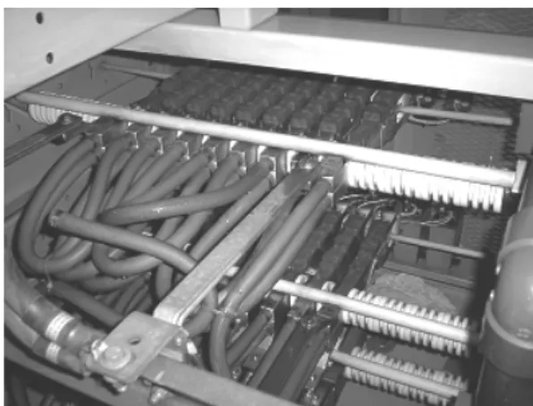
It is reported that the failure of a water cooling system for VFD (Variable Frequency Drive) of Pyungtack Unit 1 Facility (the Western Power Co. in Korea). The system has been operated for about 15 years, though the actual running time was not known. The induction motor of VFD is operating at the rate of 3200 HP. This motor is used to drive forced draft fans. The cooling system transfers heat from the thyristor bridges to the fluid, being passed into the heat exchanger. The fluid is a mixture of water and glycol to permit an operating temperature of -40 ℃ to +74 ℃. The water-glycol mixture (25% by volume) cir- culates through the deionized water tank to maintain the fluid resistivity level. The system is a closed-loop system, as shown in Fig. 1, with a reservoir into which fluid is added from time to time to replenish evaporation loss. The heated fluid leaving the heatsinks is drawn in by the pump.
Output fluid from the pump goes into the heat exchanger for cooling. The cooled fluid returning form the heat ex- changer goes to the heatsinks, preventing the temperature of the heatsinks from becoming too high.1)
Fig. 1. Schematic of the VFD cooling system
2. Visual inspection
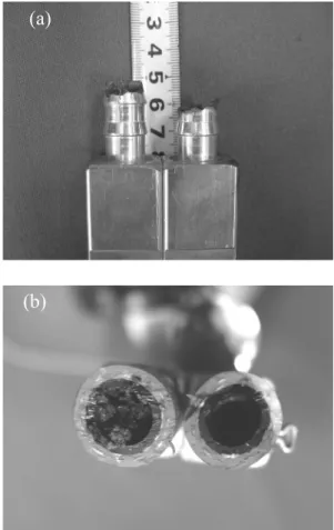
Fig. 2 shows a couple of the U-shaped heatsinks, as assembled into the system (a) and as detached therefrom (b). Fig. 2 shows that one of the heatsink was partly dam- aged at the connection and disconnected from the hose, leading to a leak. It can be seen that a damaged nipple of the heatsink, outlet nipple in this case. The failure was found repeatedly at the nipples of certain location through- out the whole system consisting of 9 U-shaped heatsink modules. Furthermore, there were no heatsink modules
JINE-SUNG JUNG, HAN-SANG LEE, MIN-TAE KIM, AND EUI-HYUN KIM
154 CORROSION SCIENCE AND TECHNOLOGY Vol.8, No.4, 2009
where the inlet and outlet nipples were damaged con- currently. This suggests a kind of galvanic corrosion. From a closer inspection, as shown in Fig. 3(a), it can be seen that one of the nipples maintains its original shape with some color change at the tip, while the tip of the other nipple was severely eroded away. Inside of the sound nip- ple and hose attached to this nipple were almost stuffed by corrosion-products, while that of the eroded was rela- tively clean, as shown in Fig. 3(b). The inside of the heat- sink remained unattacked, by an inspection using an endo- scope, as shown in Fig. 4. Some corrosion-products were in blue-green color in the filter, seemingly originated from the corrosion of the nipple, as shown in Fig. 5.
3. Analysis of corrosion products
In order to identify the cause of the failure, corro- sion-products accumulated at the inlet and outlet of the heat sink and in the filter, and the surface of a damaged outlet nipple were analyzed. Their chemical composition and micro-morphology were obtained with a scanning
(a)
(b)
Fig. 2. A couple of U-shaped heatsinks showing the failure at the connection: (a) as assembled into the system; (b) as detached therefrom.
electron microscope (SEM) equipped with energy-dis- persive spectrometer (EDX).
3.1 Corrosion-products
Fig. 6 shows the morphology of the corrosion-products taken by SEM accumulated (a) at the inlet and (b) outlet side. As shown, the corrosion-products have different
(a)
(b)
Fig. 3. A closer inspection of the nipples (a) and hoses (b).
Fig. 4. The inside of the heatsink inspected using an endoscope.
IDENTIFICATION OF THE FAILURE OF VFD HEAT SINK AT FOSSIL POWER PLANT
CORROSION SCIENCE AND TECHNOLOGY Vol.8, No.4, 2009 155 Fig. 5. Corrosion-products in blue-green color found in the filter.
(a)
(b)
Fig. 6. The morphology of the corrosion-products taken by SEM : (a) inlet and (b) outlet.
morphologies. Smaller grains are agglomerated at the out- let side, while bigger crystal-like grains are well adhered on the inlet side.
The chemical compositions of these products were taken from EDX measurements, and are listed in Tables 1-3.
As shown in these tables, the corrosion products are mostly composed of copper and oxygen. However, there is some
difference in the composition between the inlet and outlet side. From Tables 1 and 2 (from the atomic %), the corro- sion-products accumulated at the inlet is expected to be in the form of Cu(OH)2, and those at the outlet side Cu2O.2)-5) Those at the filter have almost the same chemical composition as those of inlet, as listed in Table 3.
3.2 Analysis of the nipple at the outlet side
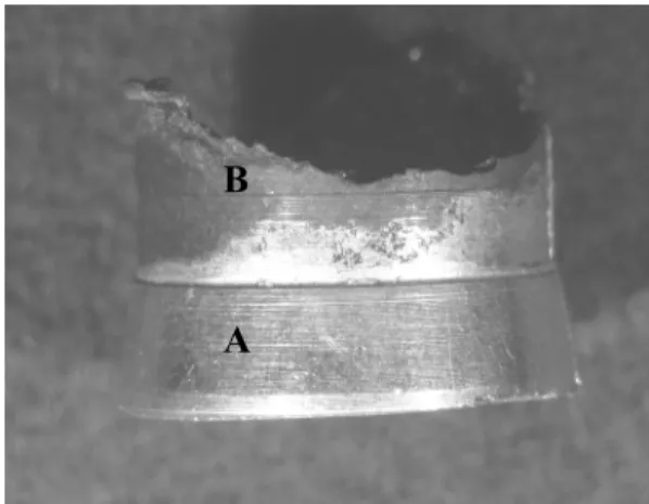
As shown in Fig. 8, some part of the tip of the eroded outlet nipple lost its original color. The color has been changed from metallic white into black-brown. In this part, a corrosive element, Cl, was detected in a considerable amount.(Table 4)
Table 1. Chemical composition of the corrosion-products accu- mulated at the inlet.
O Cu Ni Zn
w/o 33.52 61.45 1.07 3.96
a/o 66.70 30.79 0.58 1.93
Table 2. Chemical composition of the corrosion-products accu- mulated at the outlet
O Cu Cl Sn
w/o 13.24 84.77 0.39 1.60
a/o 37.86 61.03 0.50 0.62
Fig. 7. The morphology of the corrosion-products at the filter.
Table 3. Chemical composition of the corrosion-products accu- mulated at the filter.
O Cu Zn
w/o 31.60 65.23 3.17
a/o 64.75 33.66 1.59
JINE-SUNG JUNG, HAN-SANG LEE, MIN-TAE KIM, AND EUI-HYUN KIM
156 CORROSION SCIENCE AND TECHNOLOGY Vol.8, No.4, 2009
A B
Fig. 8. The morphology of the eroded outlet nipple: metallic white (A) and black-brown (B).
Table 4. Chemical composition of the surface of the nipple, w/o (a/o)
O Cl Cu Sn
A 5.02 (28.15) - - 94.98 (71.85)
B 22.49 (60.07) 12.45 (15.16) 1.61 (1.09) 63.45 (23.08)
4. Summary
Failure of the heat sink of the VDF systems was oc- curred due to the aqueous corrosion at the nipple tip of the heat sink attached to polymer hoses. Among the total 9 heat sink with an inlet and an outlet nipple for each heatsink, exactly 9 nipples were damaged at the tip. The heat sink was composed of Sn-coated copper, and thus the corrosion-products were mostly copper compounds.
The nipple at a position was corroded due to Cl ions which accumulated at the inside of the nipple of the other side.
References
1. Technical manual for Variable Frequency Drive, Ross Hill Controls Corp., 1989
2. T. H. Merkel, etc, Water Research, 36, 1547 (2002).
3. M. Edwards, etc, Corrosion Science, 43, 1 (2001).
4. S. Sathiyanarayanan, etc, Corrosion Science, 41, 1899 (1999).
5. B. Millet, etc, Corrosion Science, 37, 1903 (1995).