CopyrightⒸ2011 KSAE 1225-6382/2011/109-1 3 Transactions of KSAE, Vol. 19, No. 1, pp.89-94 (2011)
고효율 Oval형 EGR 쿨러 개발에 관한 연구
이 준*1)․문 전 일1)․한 창 석2)
호서대학교 로봇공학과1)․호서대학교 국방과학기술학과2)
A Study on Development of Oval Type High Efficient EGR Cooler
Joon Lee*1)․Jeon-Il Moon1)․Chang-Suk Han2)
1)Department of Robotic Engineering, Hoseo University, Chungnam 336-795, Korea
2)Department of Defence Science & Technology, Hoseo University, Chungnam 336-795, Korea (Received 26 February 2010 / Accepted 16 August 2010)
Abstract : The EGR system is one of important components in diesel engine. The regulation on NOx emission has been tightened up. Therefore, it is a significant issue to develop and commercialize the high efficient EGR cooler system that reduces NOx emission in DI diesel engine. Key performance factor of the EGR cooler system is how to properly design both wavy cooling fins and gas tubes. This paper proposes a high efficient EGR cooler that has been upgraded with both the optimized wavy cooling fins and the improved shape of structure. The evaluation of the heat exchange efficiency, outlet temperature, and gas pressure drop of the EGR cooler is performed with the prototype of the proposed EGR cooler. The result shows a good solution and will be implemented to the model of a clean diesel engine being developed for both domestic and overseas market.
Key words : EGR system(배기가스 재순환 장치), EGR cooler(배기가스 재순환 냉각기), Wavy-fin(열교환 핀), NOx(질소산화물)
1. 서 론1)
자동차의 주 동력원으로 사용되는 디젤 엔진은 1896년 Rudorf Diesel에 의해 발명된 후 우수한 출력 성능과 연비효율, 저 이산화탄소 배출, 내구 신뢰성 등의 장점으로 자동차분야 및 산업계에 널리 쓰이 고 있다.
21세기에 들어와 지구온난화 등 자동차에 의한 대기공해가 더욱 가속화 되고 있어 세계 각국은 자 동차배기가스 규제를 갈수록 엄격히 규정하고 있 다.1) 디젤엔진의 배기에는 NOx(Nitro Oxides: 질소 산화물) 및 그을음 등의 입자상 물질(PM: particulate matter)이 배출되는데 발암성 물질로 알려지게 되면
*Corresponding author, E-mail: [email protected]
서 자동차에 의한 대기오염의 주범으로 인식되고 있어 디젤엔진 차량의 존속을 위협하고 있다.2)
NOx 저감을 위해 제안된 배기가스 재순환(EGR:
exhaust gas recirculation) 장치의 성능 향상을 위해서 엔진 냉각수를 이용하여 강제 냉각시키는 cooler가 적용된 cooled type EGR system이 디젤 자동차에 적 용되고 있지만,3) 향후 적용될 Euro-6 디젤 배기규제 를 만족하기 위해서 디젤엔진의 다양한 운전영역에 서 성능과 배기가스 규제를 만족하는 고효율 EGR cooler 개발의 필요성이 요구되고 있다.4,5)
본 논문에서는 기존 디젤엔진의 배기가스 재순환 장치의 cooler 성능을 개선하기 위한 최적구조를 제 시하고 평가하고자 한다.
이 준․문전일․한창석
2. 본 론
2.1 Oval Type EGR Cooler의 제안
본 연구에서는 Fig. 1의 기존 shell & tube type EGR cooler와 차별화된 고효율 EGR cooler의 개발 을 위해 아래와 같은 설계 사양을 제안하였다.
1) 가스 유입면적 극대화, 유동흐름 방해면적 최 소화
2) 가스 유동성 향상 및 유속 증대 3) 가스 및 coolant ΔP 저감
4) wavy fin 설계 및 적용을 통한 난류 형성으 로 anti-fouling성 향상
5) 전열면적 극대화 실현
6) NOX 저감으로 배기가스 규제 능동대응 상기 사항의 만족을 위해 oval type의 gas tube와 열전달 면적을 증대시킨 wavy-fin을 병행하는 설계 사양을 제안하였다.
Fig. 2는 oval type EGR cooler의 개념도이다. 기존 의 shell & tube EGR cooler에 비해 열교환 성능 및 내 구성 확보를 위해 열교환 면적을 극대화하였다. 이 를 위한 방안으로 가스튜브 형상을 변경하고 wavy-fin을 내부에 삽입하였다.
현재 양산되고 있는 shell & tube type EGR cooler 는 내부에 다수의 원형 가스튜브가 삽입된 구조이 다. 또 가스튜브에는 나선형 groove가 형성되어 있
Fig. 1 The photograph of shell & tube type EGR cooler
Fig. 2 The concept of oval type EGR cooler
어서 가스의 난류 형성 및 열전달 면적이 증대된다.
전체 열전달은 가스튜브 외벽과 나선형 groove에 의 해 이루어진다.
그러나 oval type EGR cooler의 경우, Fig. 3과 같이 가스튜브 내부에 브레이징 용접으로 삽입된 얇은 wavy-fin에 의해 난류가 형성되고 이 fin에 의해 1차 적인 열전달이 일어나서 oval gas tube로 전달되어 냉각수에 의한 2차 열전달이 일어난다.6)
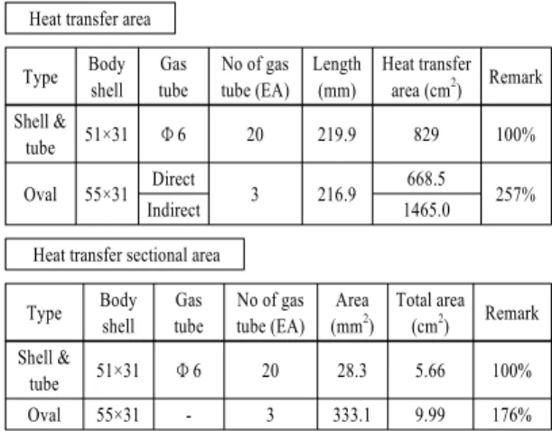
Fig. 3 The internal structure of oval type EGR cooler Table 1 The comparison of heat transfer area for shell &
tube vs oval type EGR cooler Heat transfer area
Type Body shell
Gas tube
No of gas tube (EA)
Length (mm)
Heat transfer area (cm2) Remark Shell &
tube 51×31 Φ 6 20 219.9 829 100%
Oval 55×31 Direct
3 216.9 668.5
Indirect 1465.0 257%
Heat transfer sectional area
Type Body
shell Gas tube
No of gas tube (EA)
Area (mm2)
Total area (cm2) Remark Shell &
tube 51×31 Φ 6 20 28.3 5.66 100%
Oval 55×31 - 3 333.1 9.99 176%
고효율 Oval형 EGR 쿨러 개발에 관한 연구
Table 1에서 보듯이 가스튜브만으로 형성된 직접 적인 열전달 면적이 약 20% 감소되지만 wavy-fin에 의한 간접적인 열전달 면적이 증대되어 기존 shell &
tube type 대비 열전달 면적이 약 1.5배 이상 증대되 었다.7)
또 EGR cooler의 성능에 중요한 요소인 가스 압력 강하를 최소화하기 위해 oval gas tube가 shell & tube 보다 훨씬 유리하다. flange로 유입된 가스가 유입면 적이 극대화된 oval gas tube로 원활히 공급되어 유 동성이 개선되었다.
2.2 Oval Type EGR Cooler 개발
제안된 oval gas tube 및 wavy-fin의 형상에 따른 성능향상의 검증을 위해 배기량 2.0L급 디젤엔진에 맞는 EGR cooler를 시제작 하였다.
Fig. 4에서 보듯이 좌측은 현재 양산중인 shell &
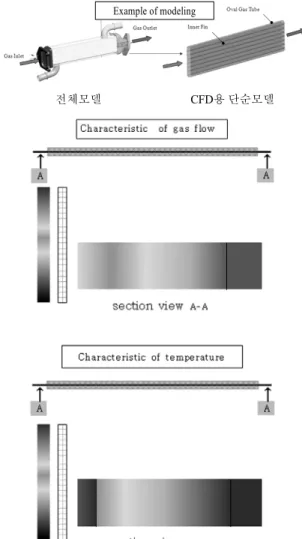
tube type EGR cooler이고 우측은 oval type EGR cooler 이다. Fig. 5는 oval 가스튜브 내의 가스유동 및 열전달에 의한 온도특성을 나타낸다. 난류모델 은 표준 K-ε 모델을 사용하였다. 가스유동이 원활히 일어나고 가스온도가 냉각수에 의해 양호하게 냉각 되고 있음을 알 수 있다.
열교환 성능에 직접 영향을 미치는 wavy-fin의형 상은 Fig. 6과 같이 끝단이 square type으로 피치와 높 이가 각각 6.0mm 이고 수평단면의 형상이 물결모양 이다. 배기가스가 이 물결모양의 fin 사이를 지나갈 때 난류가 발생되어 fin에 퇴적되어 있는 카본을 제 거한다.
(a) Shell & tube type (b) Oval type
Fig. 4 The comparison of shell & tube vs oval type EGR cooler
Example of modeling
전체모델 CFD용 단순모델
Fig. 5 The characteristic of gas flow & temperature contour in oval type EGR cooler
horizontal section
Fig. 6 The schematic of square type wavy-fin
Joon Lee․Jeon-Il Moon․Chang-Suk Han
Table 3 The comparison table of performance test results Condition (rpm) Gas out temp
(°C)
Gas side △P (kPa)
Wate out temp (°C)
Water side △P (kPa)
Efficiency (%) Shell & tube type
EGRC
1700 120.8 3.9 92.3 3.1 83.7
2500 153.8 6.7 94.2 6.0 82.4
3200 183.3 9.7 95.0 8.5 81.9
Oval type EGRC
1700 110.4 2.1 92.7 3.5 89.2
2500 133.6 3.7 94.1 8.3 87.9
3200 150.8 5.3 95.2 9.8 88.2
2.3 성능 시험 결과
본 연구에서 각각의 시험은 자동차 회사의 성능 시험 기준에 준하였고 엔진회전수가 다른 세 가지 조건에서 동일한 시험을 수행하여 그 결과를 비교 분석하였다.
Table 2는 oval type EGR cooler 시험 조건으로 1700rpm, 2500rpm 및 3200rpm에서 시험을 수행하 였다.
Fig. 7은 oval type EGR cooler의 시험 사진이다.
cooler의 방열효율(η)은 아래식과 같다.
Gas
i n°C Water
out°C
Gas
i n°C Gas
out°C
상기 식을 이용하여 사진 내의 시험기에서 가스 및 냉각수 온도를 측정하여 cooler의 효율을 구하 였다.
Table 3은 Table 2의 시험조건에서 shell & tube type 및 oval type의 성능 시험 결과를 나타내었다. 방 열효율은 shell & tube type에서 1700, 2500 및 3200rpm 별로 각각 83.7%, 82.4% 및 81.9%이며 oval type에서는 89.2%, 87.9% 및 88.2%이다. 가스 측 압 력강하는 shell & tube type에서 1700, 2500 및 3200rpm 별로 각각 3.9kpa, 6.7kpa 및 9.7kpa이며, oval type에서는 2.1kPa, 3.7kpa 및 5.3kpa이다. oval
Table 2 Performance test condition
items Engine speed (rpm)
1700 2500 3200
Coolant inlet temp. (°C) 90 90 90
Gas inlet temp. (°C) 280 452 605.5
Coolant flow rate (l/min) 13 20 28
Gas flow rate (kg/h) 52 63 75
abs. air pressure (bar) 1.6 1.6 1.6
Fig. 7 The photograph of heat dissipation test with EGR cooler
type이 shell & tube type 보다 모두 양호한 결과를 보 여주고 있다.
Fig. 8은 Table 2의 시험조건에서 엔진회전수변화 에 따른 결과를 도식화하였다. 엔진회전수 증가에 따른 출구 온도의 상승이 shell & tube type에 비하여 oval type이 약 10 ~ 30°C 정도 낮게 완만하게 상승하 고 있다. 이는 oval type EGR cooler의 양호한 열전달 특성에 기인된 현상이다.
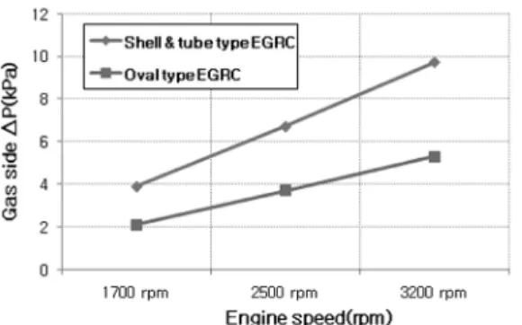
Fig. 9는 엔진회전수 증가에 따른 가스유량 증대 에 기인된 가스 측 압력강하를 보여 주고 있다. 압력
Fig. 8 Diagram for gas out temperature
A Study on Development of Oval Type High Efficient EGR Cooler
Fig. 9 Diagram for gas side △P
Fig. 10 Diagram for water side △P
Fig. 11 Diagram for Efficiency
강하 선도는 선형적으로 증가하고 있으며, shell &
tube type에 비해 oval type의 증가 경향이 완만한 형 태를 보여주며 최대 4.4kPa 정도 낮다. 이는 oval type EGR cooler가 가스가 통과하는 단면적이 크기 때문 이다.
Fig. 10은 엔진회전수 증가에 따른 냉각수 압력강 하를 보여준다. 저속에서는 냉각수 압력강하가 비 슷한 수준이지만 고속으로 갈수록 oval type이 shell tube type 보다 현저히 낮다. 즉 cooler 내부의 냉각수 흐름이 oval type경우 훨씬 더 양호함을 알 수 있다.
Fig. 11은 엔진회전수 증가에 따른 EGR cooler의 방열효율을 나타낸다. oval type이 shell & tube type
과 비교하여 약 5 ~ 6% 양호하다. 이는 Table 1에서 보는 바와 같이 oval type EGR cooler의 우수한 열전 달 특성 때문이라고 사료된다.
3. 결 론
Oval type EGR cooler의 설계 및 개발과 성능시험 을 통해 다음과 같은 결론을 도출하였다.
1) Oval gas tube 내에 wavy-fin을 삽입한 경우 가스 튜브에 의한 직접적인 열전달 면적은 기존 shell
& tube type EGR cooler 대비 약 20% 감소한 반면 wavy-fin에 의한 간접적인 열전달 면적은 약 1.7 배 증대되어 전체 열전달 면적은 약 1.5배 증가되 었다.
2) Oval gas tube 적용에 따라 실제 가스 유입 부 면 적이 증가 되어 가스 유동 방해 면적이 감소하여 가스 압력강하를 최소화 할 수 있었다.
3) 실제 가스 유입 부 면적 증대에 따른 유동성 향상 및 유속 증대가 이루어졌다.
4) 향후 wavy-fin pitch 및 형상 변경을 통하여 추가 적인 열교환 효율증대 및 가스 압력강하 저감이 가능할 것으로 사료된다.
후 기
“이 논문은 2009년도 호서대학교의 재원으로 학 술연구비(과제번호: 20090223) 지원에 의해 수행된 연구입니다.”
References
1) M. P. Walsh, “Global Trends in Diesel Emi- ssions Control,” SAE 970179, pp.101-109, 1997.
2) D. T. Montgomery and R. D. Reitz, “Six-Mode Cycle Evaluation of the Effect of EGR and Multiple Injection on Particulate and NOx Emission from a DI Diesel Engine,” SAE 960316, pp.15-19, 1996.
3) J. W. Lim, B. M. Kang, J. S. Park, J. K. Yeom, S. S. Chung and J. Y. Ha, “A Study on the Effects of EGR Temperature on Emission Characteristic in a HSDI Diesel Engine using
이 준․문전일․한창석
EGR Cooler,” Fall Conference Proceedings, KSAE, pp.306-312, 2004.
4) Nies, Jens, Use of Simulation Tools in EGR Design Process. 3. Vehicle Thermal Manage- ment Systems Conference (VTMS 5). Nash- ville, Tenn., pp.65-70, 2001.
5) A. Solz, F. Fleischer, W. Knecht, J. Nies and R.
Strahle, “Development of EGR Coolers for Truck and Passenger Car Application,” 01VTMS- 97, VTMS5, pp.155-159, 2001.
6) J. P. Holman, Heat Transfer, 9th Edn, McGraw- Hill, New York, pp.233-238, 2001.
7) B. Ismail, R. Zjang, D. Ewing, J.-S. Chang, and J. Cotton, “The Heat Transfer Characteristics of EGR Cooling Device,” Proceedings of the ASME International Mechanical Engineering Congress and Exposition (IMECE). LA, USA.
ASME paper No.IMECE HT-34559, pp.207- 215, 2002.