EHL Analysis of Rolling Bearings Considering the Effect of the
Number of Rolling Elements and the Shaft Load
Sung-Ho Hong and Kyung-Woong Kim†
1School of Mechanical, Aerospace & Systems Engineering, Korea Advanced Institute of Science and Technology, Daejeon, Korea
(Received 1 October 2009; Revised 17 November 2009)
Abstract: The numerical analysis of elastohydrodynamic lubrication for the ball and roller bearings is performed in order to study the effect of the number of rolling elements and the shaft load on the minimum film thickness. A finite difference method and the Newton-Raphson method are used in the analysis. For a given shaft load, the maximum load of rolling element is determined along with the number of rolling elements. And then the minimum film thickness is calculated for several rolling bearings. The shape of film thickness and the pressure distribution are also studied.
Keywords: EHL, rolling bearings, minimum film thickness, number of rolling elements
1. Introduction
Analysis of elastohydrodynamic lubrication is used to explain lubrication phenomena in highly stressed machine elements such as cams, traction drives, rolling element bearings and to help the complete understanding of the lubrication regions, ranging from boundary to hydrodynamic. Through EHL analysis, minimum film thickness which is a very important factor to avoid metal-to-metal contact is determined. Each ball and roller in a bearing carries different load according to the number of rolling elements and position of rolling elements under given shaft load [1,2]. Therefore, it is important to grasp load acting on each rolling elements from load information of rotating axis. In this paper, after determining the maximum load of rolling element from the shaft load, minimum film thickness is calculated using a finite difference method and the Newton-Raphson method. Besides, non–uniform grid system is used to get an accurate behavior of film shapes and to reduce the number of grid points [3,4].
2. Method
To solve EHL problems of rolling bearings, Reynolds and elasticity equations are used. Moreover, variation of density and viscosity of the lubricant according to pressure is considered [5-6]. From the viewpoint of mathematical analysis, the contact between rolling element and race can be
adequately described by a rolling element with equivalent radius of curvature near a plane.
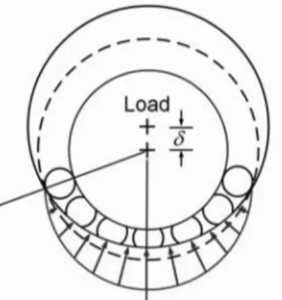
When the shaft load is applied, the interference with rolling elements, inner race and outer race is different according to the position and the number of rolling elements as shown in Fig. 1. To find the maximum load of rolling elements, equation (1) and (2) are used in ball and roller bearing. The equation related to the maximum load of rolling elements(wmax), the shaft load(wt) and the number of rolling elements(n) is as followed in ball(1) and roller bearing(2). It is assumed that rolling bearings have zero clearance [2].
(1)
(2)
3. Governing equations
3.1. Elliptic contact of ball bearing
Reynolds equation can be derived from the Navier-Stokes equation and continuity equation applying the general assumptions.
(3) where u is the mean velocity of mating surface in the rolling direction.
In nondimensional form, it becomes wmax 4.37wt n ---= wmax 4wt n ---= ∂ ∂x --- ρh 3 η --- ∂p ∂x ---⎝ ⎠ ⎛ ⎞ ∂ ∂y --- ρh 3 η --- ∂p ∂y ---⎝ ⎠ ⎛ ⎞ 12u ∂ ∂x ---( )ρh = +
†Corresponding author; [email protected] Tel: +82-42-350-3215, Fax : +82-42-350-3210
(4) where
a and b are the semimajor and semiminar axes of the hertzian contact ellipse. E is the modified modulus of elasticity.
Moreover, relation of the ellipticity parameter(k) and the ratio of equivalent radius of curvature in the x and y direction is represented as follows:
(5) where Rx and Ry are equivalent radius of curvature in the x and y direction.
The density [5] and viscosity [7] of the lubricant are described as followed in equations.
(6)
(7) where ρ0, η0 represent density and viscosity when
the pressure is zero. Z is the viscosity-pressure coefficient. Equation (6) and (7) in dimensionless form are described as follows:
(8)
(9) where E is given in GPa.
The film thickness can be defined as follows:
(10) where ho is a constant, hg(x,y) is the separation due to the geometry of the ball in the undeformed state and hd(x,y) is the amount of the elastic deformation. For the ellipsoidal solids, hg(x,y) can be written as:
(11) In dimensionless form, it becomes
(12) Elastic deformation at (x,y) due to pressure distributed over element as shown in Fig. 2 can be written as:
(13)
Equation (13) can be integrated and expressed dimensioless form as equation (14) if a uniform pressure is acting over the rectangular area. (14) where ∂ ∂X --- ρH 3 η --- ∂P ∂X ---⎝ ⎠ ⎛ ⎞ 1 k2 ---- ∂ ∂Y --- ρH 3 η --- ∂P ∂Y ---⎝ ⎠ ⎛ ⎞ 12Ub Rx --- ∂ ∂X ---(ρH) = + X x b --- Y y a --- P p E --- H h Rx --- , = , = , = , = ρ ρ ρ0 --- η η η0 --- U η0u ERx --- k a b ---= , = , = , = k 1.03 Ry Rx ---⎝ ⎠ ⎛ ⎞0.64 = ρ ρ0 1 0.58 10 9 – p × 1+1.68×10⁻⁹p ---+ ⎝ ⎠ ⎜ ⎟ ⎛ ⎞ p Pa[ ] , = η =η0 {ln( )η0 +9.67} 1 (1+5.1×10⁻⁹p) z + – { } [ ] exp ρ 1 0.58EP 1+1.68EP ---+ ⎝ ⎠ ⎛ ⎞ = η {ln( )ηo +9.67} 1 (1+5.1EP) z + – { } [ ] exp = h x y( , ) h= o+hg(x y, ) h+ d(x y, ) hg(x y, ) x 2 2Rx --- y 2 2Ry ---+ = Hg(X Y, ) 1 2 --- b Rx ---⎝ ⎠ ⎛ ⎞2 X2 Rx Ry ---k2Y2 + ⎝ ⎠ ⎛ ⎞ = d x y( , ) 2 πE --- p x( 1,y1)dx1dy1 x–x1 ( )2+(y–y1)2 ---a1 – a2
∫
b1 – b2∫
= d X Y( , ) PD= d X Y( , ) d x y( , ) Rx ---= D =2b πRx --- (X+m1) k Y( +n1)+ X m( + 1) 2 Y+n1 ( )2 + k Y( –n2)+ (X+m1)2+(Y–n2)2 ---⎝ ⎠ ⎜ ⎟ ⎜ ⎟ ⎛ ⎞ ln X–m2 ( ) k Y( –n2)+ (X–m2)2+(Y–n2)2 k Y( +n1)+ (X–m2)2+(Y+n1)2 ---⎝ ⎠ ⎜ ⎟ ⎜ ⎟ ⎛ ⎞ ln + k Y( +n1) X m1 (X+m1) 2 Y+n1 ( )2 + + + X m– 2+ (X–m2)2+(Y+n1)2 ---⎝ ⎠ ⎜ ⎟ ⎜ ⎟ ⎛ ⎞ ln +
Elastic deformation caused by the pressure acting over the lubrication region can be written as:
(15) where is an elastic influence coefficient and refers to the elastic deformation at grid point i, j caused by unit pressure acting over the rectangular pressure element at grid point k, l [3]. Therefore, film thickness in dimensionless form can be written as:
(16)
Boundary conditions are as following. The pressure vanishes on the edges of the computational domain and Reynolds condition is adjusted along the outlet boundary.
(17) The load condition in dimensionless form can be expressed as follows:
(18) where
3.2. Line contact of roller bearing
Reynolds equation in dimensionless form can be expressed as:
(19)
where
The density and viscosity of the lubricant in dimensionless form are described as equation (8), (9) like the case of ball bearing
The film thickness can be defined as equation (10).
For a cylindrical roller with axial crown profiling as shown in Fig. 3, hg(x,y) can be written as:
(20) In dimensionless form, it becomes
(21)
where
Elastic deformation caused by the pressure acting over the lubrication region can be written as:
(22) where
In dimensionless form, it becomes
(23)
where
Therefore, film thickness in dimensionless form can be written as:
(24) Boundary conditions are as following. The pressure vanishes k Y( –n2) X–m2 (X–m2) 2 Y–n2 ( )2 + + X+m1+ (X+m1)2+(Y–n2)2 ---⎝ ⎠ ⎜ ⎟ ⎜ ⎟ ⎛ ⎞ ln + m1 b1 b --- m2 b2 b --- n1 a1 a --- n2 a2 a ---= , = , = , = Hd(X Y, ) Di j k l, , , Pk l, l
∑
k∑
= Di j k l, , , H X Y( , ) H0 1 2 --- b Rx ---⎝ ⎠ ⎛ ⎞2 X2 Rx Ry ---k2Y2 + ⎝ ⎠ ⎛ ⎞ + = Di j k l, , , Pk l, l∑
k∑
+ P dP dX --- dP dY --- 0 = = = W kb 2 Rx2 ---∫∫
PdXdY = W w ERx2 ---= ∂ ∂X --- ρH 3 η --- ∂P ∂X ---⎝ ⎠ ⎛ ⎞ ∂ ∂Y --- ρH 3 η --- ∂P ∂Y ---⎝ ⎠ ⎛ ⎞ 12U ∂ ∂X ---(ρH) = + X x R --- Y y R --- P p E --- H h R --- , = , = , = , = ρ ρ ρ0 --- η η η0 --- U η0u ER ---= , = , = hg(x y, ) x 2 2R --- (y–yc) 2 2Rc ---+ = Hg(X Y, ) X 2 2 --- Y 2 Yc2 – ( ) 2RC* ---+ = Yc yc R ---- Rc* Rc R ---= , = hd Di j k l, , , Pk l, l∑
k∑
= D 2 π --- (x+b1) y a1 (x+b1) 2 y+a1 ( )2 + + + y–a2+ (x+b1)2+(y–a2)2 ---⎝ ⎠ ⎜ ⎟ ⎜ ⎟ ⎛ ⎞ ln = x–b2 ( ) y–a2+ (x–b2)2+(y–a2)2 y+a1+ (x–b2)2+(y+a1)2 ---⎝ ⎠ ⎜ ⎟ ⎜ ⎟ ⎛ ⎞ ln + y+a1 ( ) x+b1+ (x+b1)2+(y+a1)2 x–b2+ (x–b2)2+(y+a1)2 ---⎝ ⎠ ⎜ ⎟ ⎜ ⎟ ⎛ ⎞ ln + y–a2 ( ) x–b2+ (x–b2)2+(y–a2)2 x+b1+ (x+b1)2+(y–a2)2 ---⎝ ⎠ ⎜ ⎟ ⎜ ⎟ ⎛ ⎞ ln + Hd(X Y, ) D*i j k l, , , Pk l, l∑
k∑
= D*i j k l, , , Di j k l, , , R ---= H X Y( , ) H0 X 2 2 --- Y 2 Yc2 – ( ) 2RC* --- D*i j k l, , , Pk l, l∑
k∑
+ + + =on the edges of the computational domain and Reynolds condition is adjusted along the outlet boundary.
(25) The load condition in dimensionless form can be expressed as follows:
(26) where
4. Results & Discussion
The material of bearings is steel that has elastic modulus of 200GPa and poisson’s ratio of 0.3. The viscosity of the lubricant changes with the pressure as shown in Fig. 4. The pressure dependency of viscosity can be represented by the
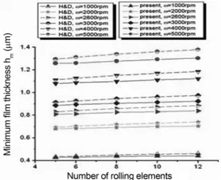
Barus equation and the Roelands equation. In the Barus equation, ηo is 0.032 Pa·s and viscosity-pressure coefficient, α, is 1.37×10⁻⁸m2/N And in the Roelands equation, ηo is also 0.032 Pa·s and viscosity-pressure coefficient, z, is 0.44 [1]. The maximum load of rolling elements in ball and roller bearing is calculated when shaft load is constant as 3830 N. Fig. 5~8 show numerical results about ball bearing and Fig. 11 represents those about roller bearing. ω is the angular velocity of the rolling element with equivalent radius of curvature.
Figure 5 shows the minimum film thickness for 1000, 2000, 3000, 4000, 5000 rpm and k = 6 in ball bearing. Present results are got by numerical EHL calculation and H&D results are calculated by formula about minimum film thickness proposed by Hamrock and Dowson [6]. The minimum film thickness calculated by formula of Hamrock and Dowson is different from that of present research because of difference in viscosity on the region that high pressure occurs as shown in Fig. 4. Present results have smaller minimum film thickness than H&D results as shown in Fig. 5. When the speed is constant, the minimum film thickness increases a little with increment of the number of rolling elements. However, the minimum film thickness increases remarkably with increment of the speed for the same number of rolling elements. Therefore, the influence of the maximum load of rolling elements on minimum film thickness is less than that of the speed.
Figure 6 represents dimensionless pressure profiles and film shapes at center line of computational region for three kinds of speed when the number of rolling elements is 12 and the ellipticity parameter is 6. Pressure spike is more distinct and the minimum film thickness is also larger at relatively high speed. The position where the minimum film thickness becomes is closer to outlet boundary at low speed rather than at high speed.
Figure 7 shows dimensionless pressure profiles and film shapes at center line of computational region for several number of rolling elements when the speed(ω = 2600 rpm) and the ellipticity parameter(k = 6) are fixed. The minimum film thickness increases with increment of the number of rolling elements. Because of a large elastic deformation at the position
P dP dX --- dP dY --- 0 = = = W =
∫∫
P Xd dY W w ER2 ---=Fig. 4. Comparision of viscosity obtained from Barus and Roelands equations for a wide range of pressure.
Fig. 5. Variation of minimum film thickness for different speed and the number of rolling elements in ball bearing (k = 6).
Fig. 6. Dimensionless pressure profiles and film shapes for different speed in the ball bearing (n = 12, k = 6).
of pressure spike, the position where minimum film thickness occurs is not same with that where pressure spike appears.
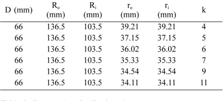
Figure 8 represents the minimum film thickness for various ellipticity parameters and several number of rolling elements in ball bearing. Figure 9 shows the cross section of the ball bearing. Table 1 shows the geometries of the ball bearing and indicates the ellipticity parameter for the geometry of ball bearing. The speed is fixed as 2600 rpm. The larger ellipticity parameter is, the larger the minimum film thickness is generated. In case of larger ellipticity parameter, side leakage of lubricant in the Y direction is not easy, so the larger minimum film thickness is calculated. Moreover, the minimum film thickness is large when the radius of inner race(ri) that
contacts with the ball is small because the ellipticity parameter of the contact is large.
Figure 10 shows the cross section of the roller bearing. And bearing geometries are listed in Table 2. The minimum film thickness for various speeds and several number of rolling
Fig. 7. Dimensionless pressure profiles and film shapes for the number of rolling elements in ball bearing (ω = 2600 rpm, k = 6).
Fig. 8. Variation of minimum film thickness for the ellipticity parameter and the number of rolling elements in ball bearing (ω = 2600 rpm).
Fig. 9. Cross section of the ball bearing.
Fig. 10. Cross section of the roller bearing.
Fig. 11. Variation of minimum film thickness for different speed and the number of rolling elements in roller bearing.
elements in roller bearing is shown in Fig. 11. Like the tendency of ball bearing, minimum film thickness increases with increment of speed and the number of rolling elements.
5. Conclusions
In this paper, to investigate the influence of the number of rolling elements in ball and roller bearing, the EHL analysis is performed by using a finite difference method, the Newton-Raphson method and non-uniform grid system. The minimum film thickness increases with increment of the number of rolling elements in rolling bearings under the same shaft load. Moreover, there is a considerable change in the minimum film thickness when the speed is changed.
Acknowledgement
This work was supported by the Brain Korea 21 Project.
References
1. Hamrock, B. J., Fundamentals of Fluid Film Lubrication, McGraw-Hill, 1994.
2. Harris, T. A., Rolling Bearing Analysis. Third edition, A Wiley-Interscience Publication, 1991.
3. Park, T. J. and Kim, K. W., A Numerical Analysis of the Elastohydrodynamic Lubrication of Elliptical Contacts, Wear, Vol. 136, pp. 299-312, 1990.
4. Park, T. J. and Kim, K. W., Elastohydrodynamic Lubrication of a Finite Line Contact, Wear, Vol. 223, pp. 102-109, 1998. 5. Dowson, D. and Higginson, G. R., Elasto-hydrodynamic
Lubrication, SI Edition, Pergamon, 1977.
6. Hamrock, B. J. and Dowson, D., Isothermal Elastohydrodynamic Lubrication of Point Contact, part-1:Theoretical Formulation, Journal of Lubrication Technology, Vol. 98, pp. 223-229.,1976., part-2:Ellipticity Parameter Results, Vol. 98, pp. 375-383., 1976., 3: Fully Flooded Results, Vol. 99, pp. 264-276., 1977., part-4: Starvation Results, Vol. 99, pp. 15-23, 1977.
7. Roelands, C. J. A., Correlational Aspects of the Viscosity-Temperature-Pressure Relationship of Lubricating Oils, Druk, V.R.B., Groningen, Nertherlands, 1966.
8. Kang, Y. and Shen, P. C. and Huang, C. C. and Shyr, S. S. and Chang, Y. P., A Modification of the Jones-Harris Method for Deep-Groove Ball Bearings, Tribology International, Vol. 39, pp. 1413-1420, 2006.
9. Yoo, G. Y. and Kim, K. W., Numerical Analysis of Grease Thermal Elastohydrodynamic Lubrication Problems using the Herschel-Bulkley Model, Tribology International, Vol. 30, pp 401-408, 1997.
Table 1. Geometries and ellipticity parameters of ball bearing D (mm) Ro (mm) (mm)Ri (mm)ro (mm)ri k 66 136.5 103.5 39.21 39.21 4 66 136.5 103.5 37.15 37.15 5 66 136.5 103.5 36.02 36.02 6 66 136.5 103.5 35.33 35.33 7 66 136.5 103.5 34.54 34.54 9 66 136.5 103.5 34.11 34.11 11 Table 2. Geometries of roller bearing
R
(mm) (mm)Ro (mm)Ri (mm)Rc (mm)yc (mm)l 33 136.5 103.5 6255 28.77 60.14