- 603 -
2세대 도체 344B를 사용한 초전도 모델 케이블에서의 과전류 특성분석
김대원*, 김아롱*, 김진근*, 박민원*, 유인근*, 조전욱**, 심기덕**, 김석호**
창원대학교*, 한국전기연구원**
Over current characteristic analysis of superconducting model cable using 2G wire 344B
Dae-Won Kim*, A-Rong Kim*, Jin Geun Kim*, Minwon Park*, In-Keun Yu*, Jeonwook Cho**, Ki-Deok Sim**, Seockho Kim**
Changwon National University*, Korea Electrotechnology Research**
Specification 22.9kV 50MVA
HTS cable Model cable
Wire type AMSC
Bi-2223
AMSC YBCO 344B
Wire stabilizer Brass Brass
Number of HTS wire 28 4
PPLP insulation 4.6mm 4.6mm
Cross sectional area
of copper stabilizer 150mm2 22mm2
Abstract - HTS tape is developed for the purpose of being applied to the power cable, motor and generator, etc. The resistance of conventional power cables is not changed a lot by over current condition. But HTS(High temperature superconductor)power cable has some different properties. The impedance of superconductor is changed due to the magnitude of current, temperature, and magnetic field. And the characteristics analysis of HTS power cable under many kind of fault conditions are important to apply real system. In addition the magnitude of over current is 10 times larger than rated current. In this paper, the characteristics of HTS power cable are analyzed when over current flows. Model cable used 2G wires was made and experimented. The results will be helpful to manufacture real HTS power cable.
1. Introduction
The peak power demand in Korea is increasing by about 4∼5%
annually, and the peak demand in 2017 will be over 68,000 MW [1].
There are many problems in extending power capacity in some areas, especially in large complex cities. Some of the problems are power quality, space for downtown substations, environmental protection, power line right-of-way and routes. HTS technology can be useful to overcome these problems. When compared to existing conventional power cables, HTS cables enable a larger transmission capacity at the same voltage. In addition, HTS power cables have higher transmission efficiency (lower power loss) resulting in a cost saving that it is expected to have high utility value in the next generation power transmission system [2]. Especially HTS power cables are presently being developed and evaluated for use in electrical grid.
These cables can offer the advantages of lower loss, lighter weight, and more compact dimensions, as compared to conventional cables [3]. Recently the HTS power cable uses 2G HTS wire. It has higher current density characteristics than 1G HTS wire. Fault states in power grid can have a magnitude of up to several times of rated current. It may cause problems and permanent damage to electrical equipment in grid. In this paper, the high temperature superconducting model cable was made by YBCO 344B wire and analyzed the characteristics of cable under over current.
2. Experimental setup
The specifications of the 22.9kV class, 50MVA HTS power cable were referred to manufacture the model cable. The conducting layer of 22.9kV class HTS power cable consists of 28 Bi-2223 brass laminated wires. Also those 28 wires are surrounded by the copper stabilizer in order to protect the over current [4]. The 22.9kV HTS power cable system which had been installed in Kochang KEPCO Power Testing Center by KERI and LS cable Co. The specifications of the 22.9kV HTS power cable and model cable used in this work are shown in Table 1. The total length of the cable is 500 mm and HTS tape is 400 mm at which voltage taps are attached to the central region of the tape with a distance of 200 mm to each other by soldering. E-type thermocouples were used for temperature measurement. Each HTS wire has copper stabilizer. Fig. 1 shows the HTS model cable and cross sectional area of the tapes. An HTS tape and copper tapes are fixed to current terminals by soldering.
The experimental circuit diagram for the tests of over current
characteristics is shown in Fig. 2. The current source is IDX power supply. Voltage and current were measured using the SCXI(signal conditioning extension for instrumentation) measurement system at 77K. The SCXI system has a high-performance signal such as temperature, voltage and current measurement system.
< TABLE 1 > Specifications of the 2G HTS model cable
(a)
(b)
< Fig. 1 > (a) Specifications of the model cable, (b)Cross sectional area
< Fig. 2 > Experimental circuit diagram for measurement 2009년도 대한전기학회 하계학술대회 논문집 2009. 7. 14 - 17
- 604 -
3. Experimental results
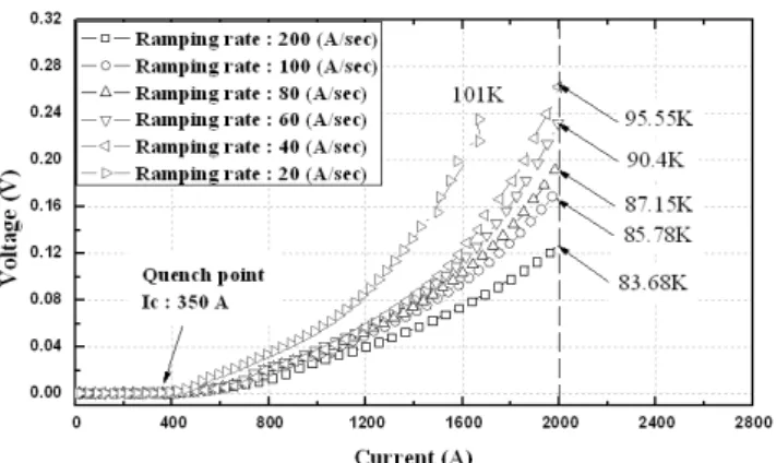
Fig. 3 shows that the critical current of HTS tape is decreased by increasing temperature. Fig. 4 shows the generated voltage of model cable under over current. The voltage is slightly increased before the quench point of model cable. Fig. 5 shows the characteristics of voltage, resistance and temperature by DC over current (Io/Ic=5). When the peak current began to be over the critical current, superconductor in HTS model cable began to get heated up slightly. But when the current passes over the quench point, the resistance occurs hastily. The authors stopped the experimenting because the temperature was increasing continuously in proportion to time when over current was transported. Fig. 6 shows the generated voltage of the model cable under various current ramp up speed.
Table 2 shows the temperature variation by over current. When current increases, the temperature of the model cable also increases in proportion to time. In Fig. 3 and table 2, the current flowing in HTS tape is decreasing because of the temperature increasing by over current and the rest of the current is transported through the stabilizer, copper.
< Fig. 3 > Characteristics of the YBCO HTS tape of critical current by increasing temperature.
< Fig. 4 > Generated voltage of the HTS model cable
< Fig. 5 > Characteristics of resistance and temperature by DC over current (Io/Ic=5)
< Fig. 6 > Generated voltage of the model cable under over current with various current ramping rate
< Table 2 > Temperature variation by over current
Io/Ic Maximum
Current(A)
Temperature(K)
Min Max △T
1 400 77.3 77.4 0.1
2 800 77.3 78 0.7
3 1200 77.3 80.2 2.9
4 1600 77.3 83.5 6.2
5 2000 77.3 85.2 7.9
4. Conclusions
The transient phenomenon of the model cable by the AC and DC over current was experimented and analyzed in this paper. The authors manufactured the HTS model cable using 2G HTS tape. The temperature and voltage characteristics of the 2G HTS model cable were measured under over current conditions with different ramp up speed. The results obtained from the experiments provide the most important data and give good information in order to design and fabricate 2G HTS power devices. The following conclusion can be drawn regarding this paper.
1. The resistance variation of the 2G HTS model cable is proportional to rising temperature.
2. After the over current experiments, critical currents degradation do not occur in the model cable.
Acknowledgement
This research was supported by a grant from Center for Applied Superconductivity Technology of the 21st Century Frontier R&D Program funded by the Ministry of Education, Science and Technology, Republic of Korea
[ References ]
[1] KEPCO (Korea Electric Power Corporation), Long-Term Prospects for Transmission System, 2005.
[2] J. Yoon, S. R. Lee, and J. Y. Kim, “Application methodology for 22.9 kV HTS cable in metropolitan city of south korea,” IEEE transactions on applied superconductivity Vol. 17, pp. 1656–-1659, 2007.
[3] Willen, D.W.A. Hansen, F. Rasmussen, C.N. Dauming, M.
Schuppach, O.E. Hansen, E. Baerentzen, J. Svarrer-Hansen, B.
Traeholt, C. “Test results of full-scale HTS cable models and plans for a 36kV, 2kArms utility demonstration”, IEEE transactions on applied superconductivity Vol. 11 No.1 pt.2, 2001, pp.2473-2476 [4] J.-H. Kim, M. Park, M. H. Ali, J. Cho, K.-D. Sim, S. Kim, H.-J.
Kim, S. J. Lee, I.-K. Yu “Investigation of the over current characteristics of HTS tapes considering the application for HTS power devices”, IEEE transactions on applied superconductivity Vol.
18, No. 2, 2008 pp.1139-1142