Vol.22, No.1, (2020), pp.7~11 https://doi.org/10.9714/psac.2020.22.1.007
```
1. INTRODUCTION
Annual power demand is continuously increasing and interconnections of substations are considered in an urban area to enhance grid stability. The interconnection of substations however is expected to increase the fault current in the event of a short circuit. This is meaning exceeding the maximum capacity of the existing circuit breaker. [1, 2].
To reduce the fault current, many kinds of superconducting fault current limiters (SFCL) have been developed and some are operating in commercial grids [3–12]. A standalone SFCL usually is installed in the substation and connected to power cables. It requires cryogenic refrigeration system and cryostat as in high temperature superconductor (HTS) power cables. Since the SFCL operating in case of fault conditions, it just consumes electric power and occupies an installation space for normal operation. To solve this inconvenience, several research efforts have been made to combine the SFCL with the HTS power cable, so called fault current limiting (FCL) HTS power cable [12, 13].
The general of HTS power cables are designed to bypass the fault current using a low resistance of copper former, where the maximum fault current is limited by an internal impedance in a transformer [14, 15]
However, the FCL HTS power cable should be designed to generate appropriated resistive impedance when the fault current is introduced while temperature of the HTS cable should be below the saturation temperature of liquid
nitrogen to ensure its dielectric strength. The resistive impedance is related material and cross section area of cable former and resistance of HTS wire itself over the critical current at quench condition. The temperature rise of the FCL HTS power cable is related to the heat capacity and the generated Joule heating. Therefore, the heat capacity should be increased while the resistance should be larger than the design value to reduce the fault current.
This paper describes a design of FCL HTS power cable of 600 MVA, 154 kV class with developed HTS wires. The target FCL function of the cable is reducing the fault current from 63 kA to less than 45 kA considering transmission level in South. To meet the allowable temperature rise and the fault current reduction, parametric studies were conducted for the resistance characteristics of the HTS wire, cross sectional area of former which is made by stainless steel and the cable length. The design process involved a thermal analysis model incorporated with an electric circuit that includes electric characteristics of FCL HTS power cable.
2. TEMPERATURE RISE OF FCL HTS POWER CABLE BY LUMPED ANALYSIS
2.1. Characteristics of HTS wire
The FCL HTS power cable utilizes the increase of resistance caused by quench of HTS wires when the fault current is introduced. Thus, designing the FCL HTS power cable is related with the resistance of HTS wire during quench status at operating temperature.
Design of HTS power cable with fault current limiting function
Dongmin Kim
a, Sungkyu Kim
b, Jeonwook Cho
b, and Seokho Kim
*, aa Changwon University, Changwon, Korea
b Korea Electrotechnology Research Institute (KERI), Changwon, Korea
(Received 19 February 2020; revised or reviewed 27 March 2020; accepted 28 March 2020)
Abstract
As demand for electricity in urban areas increases, it is necessary to improve electric power stability by interconnecting neighboring substations and high temperature superconductor (HTS) power cables are considered as a promising option due to its large power capacity. However, the interconnection of substations reduces grid impedance and expected fault current is over 45 kA, which exceeds the capacity of a circuit breaker in Korean grid. To reduce the fault current below 45 kA, a HTS power cable having a fault current limiting (FCL) function is considered by as a feasible solution for the interconnection of substations. In this study, a FCL HTS power cable of 600 MVA/154 kV, transmission level class, is considered to reduce the fault current from 63 kA to less than 45 kA by generating an impedance over 1 Ωwhen the fault current is induced. For the thermal design of FCL HTS power cable, a parametric study is conducted to meet a required temperature limit and impedance by modifying the cable core from usual HTS power cables which are designed to bypass the fault current through cable former. The analysis results give a minimum cable length and an area of stainless steel former to suppress the temperature of cable below a design limit.
Keywords: impedance, fault current, former, HTS power cable, quench
* Corresponding author: [email protected]
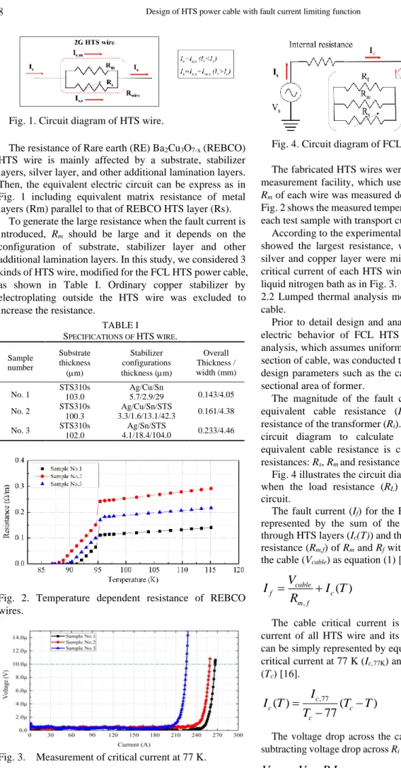
The resistance of Rare earth (RE) Ba
2Cu
3O
7-x(REBCO) HTS wire is mainly affected by a substrate, stabilizer layers, silver layer, and other additional lamination layers.
Then, the equivalent electric circuit can be express as in Fig. 1 including equivalent matrix resistance of metal layers (Rm) parallel to that of REBCO HTS layer (Rs).
To generate the large resistance when the fault current is introduced, R
mshould be large and it depends on the configuration of substrate, stabilizer layer and other additional lamination layers. In this study, we considered 3 kinds of HTS wire, modified for the FCL HTS power cable, as shown in Table I. Ordinary copper stabilizer by electroplating outside the HTS wire was excluded to increase the resistance.
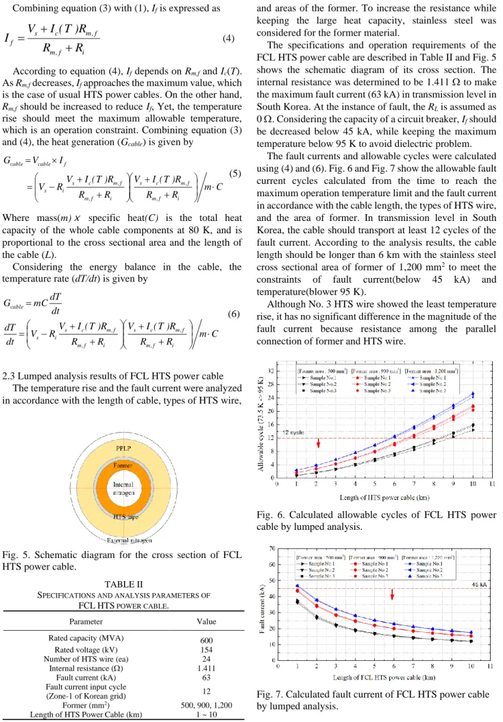
Fig. 2. Temperature dependent resistance of REBCO wires.
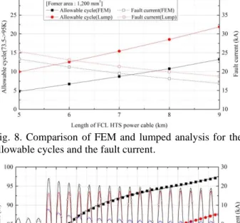
Fig. 3. Measurement of critical current at 77 K.
Fig. 4. Circuit diagram of FCL HTS power cable.
The fabricated HTS wires were installed in a resistance measurement facility, which uses a G-M cryocooler, and
Rmof each wire was measured depending on temperature.
Fig. 2 shows the measured temperature resistance curve for each test sample with transport current of 1 A.
According to the experimental results, the sample No. 2 showed the largest resistance, where the thicknesses of silver and copper layer were minimized. In addition, the critical current of each HTS wire was also measured in a liquid nitrogen bath as in Fig. 3.
2.2 Lumped thermal analysis model of FCL HTS power cable.
Prior to detail design and analysis on the thermal and electric behavior of FCL HTS power cable, a lumped analysis, which assumes uniform temperature in the cross section of cable, was conducted to investigate the effect of design parameters such as the cable length and the cross sectional area of former.
The magnitude of the fault current is determined by equivalent cable resistance (R
cable) and the internal resistance of the transformer (R
i). Fig. 4 shows a simplified circuit diagram to calculate the fault current. The equivalent cable resistance is calculated by the parallel resistances: R
s, R
mand resistance of former (R
f).
Fig. 4 illustrates the circuit diagram for the fault current when the load resistance (R
L) becomes zero by short circuit.
The fault current (I
f) for the FCL HTS power cable is represented by the sum of the critical current flowing through HTS layers (I
c(T)) and the current thourgh parallelresistance (R
m,f) of R
mand R
fwith the voltage drop across the cable (V
cable) as equation (1) [16].
, cable
( )
f c
m f
I V I T
= R + (1)
The cable critical current is the sum of the critical current of all HTS wire and its temperature dependency can be simply represented by equation (2) considering the critical current at 77 K (I
c,77K) and the critical temperature (T
c) [16].
( )
,77( )
77
c
c c
c
I T I T T
= T −
− (2) The voltage drop across the cable in (1) is obtained by subtracting voltage drop across R
ifrom V
sas in equation (3).
f i s
cable
V R I
V = − (3) Fig. 1. Circuit diagram of HTS wire.
TABLE I
SPECIFICATIONS OF HTS WIRE. Sample
number
Substrate thickness
(m)
Stabilizer configurations thickness (m)
Overall Thickness / width (mm)
No. 1 STS310s
103.0
Ag/Cu/Sn
5.7/2.9/29 0.143/4.05
No. 2 STS310s
100.3
Ag/Cu/Sn/STS
3.3/1.6/13.1/42.3 0.161/4.38
No. 3 STS310s
102.0
Ag/Sn/STS
4.1/18.4/104.0 0.233/4.46
TABLE II
SPECIFICATIONS AND ANALYSIS PARAMETERS OF
FCLHTS POWER CABLE.
Parameter Value
Rated capacity (MVA) 600
Rated voltage (kV) 154
Number of HTS wire (ea) 24
Internal resistance () 1.411
Fault current (kA) 63
Fault current input cycle
(Zone-1 of Korean grid) 12
Former (mm2) 500, 900, 1,200
Length of HTS Power Cable (km) 1 ~ 10
Combining equation (3) with (1), I
fis expressed as
i f , m
f , m c s
f
R R
R ) T ( I I V
+
= + (4)
According to equation (4), I
fdepends on R
m,fand I
c(T).
As R
m,fdecreases, I
fapproaches the maximum value, which is the case of usual HTS power cables. On the other hand,
Rm,fshould be increased to reduce I
f, Yet, the temperature rise should meet the maximum allowable temperature, which is an operation constraint. Combining equation (3) and (4), the heat generation (G
cable) is given by
C R m
R R ) T ( I V R R
R ) T ( I RV V
I V G
i f , m
f , m c s
i f , m
f , m c s i s
f cable cable
+ +
+
− +
=
=
(5)
Where mass(m) ⅹ
specific heat(C) is the total heatcapacity of the whole cable components at 80 K, and is proportional to the cross sectional area and the length of the cable (L).
Considering the energy balance in the cable, the temperature rate (dT/dt) is given by
C R m
R R ) T ( I V R R
R ) T ( I RV dt V
dT
dt mCdT G
i f , m
f , m c s
i f , m
f , m c s i s cable
+ +
+
− +
=
=
(6)
2.3 Lumped analysis results of FCL HTS power cable The temperature rise and the fault current were analyzed in accordance with the length of cable, types of HTS wire,
Fig. 5. Schematic diagram for the cross section of FCL HTS power cable.
and areas of the former. To increase the resistance while keeping the large heat capacity, stainless steel was considered for the former material.
The specifications and operation requirements of the FCL HTS power cable are described in Table II and Fig. 5 shows the schematic diagram of its cross section. The internal resistance was determined to be 1.411 to make the maximum fault current (63 kA) in transmission level in South Korea. At the instance of fault, the R
Lis assumed as 0 . Considering the capacity of a circuit breaker, I
fshould be decreased below 45 kA, while keeping the maximum temperature below 95 K to avoid dielectric problem.
The fault currents and allowable cycles were calculated using (4) and (6). Fig. 6 and Fig. 7 show the allowable fault current cycles calculated from the time to reach the maximum operation temperature limit and the fault current in accordance with the cable length, the types of HTS wire, and the area of former. In transmission level in South Korea, the cable should transport at least 12 cycles of the fault current. According to the analysis results, the cable length should be longer than 6 km with the stainless steel cross sectional area of former of 1,200 mm
2to meet the constraints of fault current(below 45 kA) and temperature(blower 95 K).
Although No. 3 HTS wire showed the least temperature rise, it has no significant difference in the magnitude of the fault current because resistance among the parallel connection of former and HTS wire.
Fig. 6. Calculated allowable cycles of FCL HTS power cable by lumped analysis.
Fig. 7. Calculated fault current of FCL HTS power cable
by lumped analysis.
3. FEM ANALYSIS OF FCL HTS POWER CABLE
3.1 FEM analysis model of FCL HTS power cable The lump analysis assumes the same temperature in the cross section of cable, but the actual temperature distribution in the cross section varies with the radial distance, depending on the heat capacity and the heating power of individual components such as the stainless steel former and the HTS layer. To consider the detail temperature distribution, 2D FEM analysis was conducted the radial heat transfer between components in Fig. 5.
In order to distinguish the local heat generations in the former and the HTS layer, the current in each layer and resultant heat generations should be separated as in the circuit diagram of Fig. 4. The voltage drop of cable can be obtained combining (1) and (3) as in (7). Then, I
formerand
Iwirecan be determined by (8).
,
( ) 1
s i c
cable
i m f
V R I T
V R
R
= − +
(7)
cable
,
former wire f former
f
I V I I I
= R = − (8)
To calculate the transient heat transfer and the variation of fault current, a commercial FEM analysis software,
comsolmultiphysics ver. 5.2, was adapted using a fullycoupled heat transfer and electric circuit module. The Joule heating of each layer is calculated by V
cable, I
formerand I
fto be used in the heat transfer module. The low thermal conductivity of insulation layer of PPLP (polypropylene laminated paper) and temperature boundary condition were considered [17]. The resultant temperature is reflected in the calculation of I
c(T) and temperature dependent electric resistivity.
3.2 Analysis results of FCL HTS power cable
In the analysis model, the sample No. 3 was considered due to its largest resistance. Table III shows the analysis parameters.
According to the FEM analysis, the concentrated heat generation in the thin HTS layer increased the temperature more and the resultant allowable fault cycles decreased at the same cable length compared with the lumped analysis.
And the fault current was decreased from FEM analysis due to the increased temperature of HTS wire. Fig. 8 compares the FEM analysis with the lumped analysis.
Fig. 9 shows a representative FEM analysis result of 9 km that meets the temperature and fault current constraint.
In this case, the allowable fault cycle was 13 cycles and the fault current was 17 kA.
4. SUMMARY AND CONCLUSION
In this study, we developed a simplified lumped analysis model to design of a FCL HTS power cable. For the precise modelling, the resistances of manufactured HTS wires were measured and taken into the analysis model.
Through the lumped analysis model, it was confirmed that the cable length should be longer than 6 km with a stainless steel cross sectional area of former of 1,200 mm
2to limit the maximum temperature below 95 K while reducing the fault current below 45 kA from 63 kA. For more precise simulation, FEM analysis was conducted with the cross section of the cable using a fully coupled heat transfer and electric circuit model. Due to the localized heat generation and poor heat transfer between the HTS layer and stainless steel former, the temperature of HTS layer increased more than the lumped model. In this case, the required cable length was increased to 9 km.
Through the lumped analysis and FEM analysis, it was possible to obtain the required cable length and the cross sectional area of former by increasing both the resistance and heat capacity. However, it is not thought to be easy to meet our design requirements with only resistive impedance due to the large fault current and the grid voltage in Korea transmission grid. To meet the design requirements with a short length of the cable, other impedance generation mechanism, such as inductive impedance, should be incorporated. Whereas it may be possible to obtain an appropriate design results for the distribution level grid, where the grid voltage is 22.9 kV and maximum fault current is 25 kA.
Fig. 8. Comparison of FEM and lumped analysis for the allowable cycles and the fault current.
Fig. 9. Representative FEM analysis results for the variation of temperature and fault current when the cable length is 9 km.
TABLE III
F
EM ANALYSIS PARAMETERS.
Parameter Value
Length of HTS power cable (km) 5 ~ 9 Cross sectional area of former (mm2) 1,200
HTS wire No.3
Initial temperature (K) 73.5
ACKNOWLEDGMENT
This supported by the Korea Institute of Energy Technology Evaluation and Planning (KETEP) and the Ministry of Trade, Industry & Energy (MOTIE) of the Republic of Korea (No. 20171220100400), and the National Research Foundation of Korea (NRF) grant funded by the Korea government (MSIT) (No.
2019R1A5A808320111)
REFERENCES
[1] L. Ye, M. Majoros, T. Coombs, and A. M. Campbell, “System studies of the superconducting fault current limiter in electrical distribution grids,” IEEE Trans. Appl. Supercond., vol. 17, no. 2, pp.
2339–2342, 2007.
[2] Y. Jia, J. Yuan, Z. Shi, H. Zhu, Y. Geng, and J. Zou, “Simulation method for current-limiting effect of saturated-core superconducting fault current limiter,” IEEE Trans. Appl.
Supercond.,vol. 26, no.4, pp. 1-4. 2016.
[3] M. C. H. V. M. R, “A review on super conducting fault current limiter ( SFCL ) in power system,” Int. J. of Eng. Research and General Science, vol. 3, no. 2, pp. 485–489, 2015.
[4] S. Yadav, G. K. Choudhary, and R. K. Mandal, “Review on fault current limiters,” Int. J. Eng. Res. Technol., vol. 3, no. 4, pp.
1595–1604, 2014.
[5] S. H. Lim, “Comparative study on current limiting characteristics of flux-lock type SFCL with series or parallel connection of two coils,” Phys. C Supercond., vol. 468, no. 15–20, pp. 2076–2080, 2008.
[6] B. Li, F. Guo, J. Wang, and C. Li, “Electromagnetic transient analysis of the saturated iron-core superconductor fault current limiter,” IEEE Trans. Appl. Supercond., vol. 25, no. 3, pp. 1-5, 2015.
[7] M. Chen et al., “6.4 MVA resitive fault current limiter based on Bi-2212 superconductor,” Phys. C Supercond., vol. 372–376, no.
PART 3, pp. 1657–1663, 2002.
[8] S. Srilatha and K. V. Reddy, “Analysis of positioning of superconducting fault current limiter in smart grid application,”
INTERNATIONAL JOURNAL OF ADVANCED AND
INNOVATIVE RESEARCH, no. January 2012, pp. 24-31, 2016.
[9] R. Dommerque et al., “First commercial medium voltage superconducting fault-current limiters: Production, test and installation,” Supercond. Sci. Technol., vol. 23, no. 3, 2010.
[10] J. G. Kim et al., “HTS power cable model component development for PSCAD/EMTDC considering conducting and shield layers,”
IEEE Trans. Appl. Supercond., vol. 19, no. 3, pp. 1785–1788, 2009.
[11] C. Neumann, “Superconducting fault current limiter (SFCL) in the medium and high voltage grid,” 2006 IEEE Power Eng. Soc. Gen.
Meet., pp. 1–6, 2006.
[12] C. M. Rey et al., “Test results for a 25 meter prototype fault current limiting HTS cable for project hydra,” AIP Conf. Proc., vol. 1218, pp. 453–460, 2010.
[13] J. Maguire et al., “Status and progress of a fault current limiting HTS cable to be installed in the con Edison grid,” AIP Conf. Proc., vol. 1218, no. 3, pp. 450 2010.
[14] J. H. Kim et al., “Investigation of the over current characteristics of HTS tapes considering the application for HTS power devices,”
IEEE Trans. Appl. Supercond., vol. 18, no. 2, pp. 1139–1142, 2008.
[15] M. Yagi et al., “Design and evaluation of 275 kV-3 kA HTS power cable,” Phys. Procedia, vol. 45, pp. 277–280, 2013.
[16] Y. Iwasa, Case studies in superconducting magnets: Design and operational issues: Second edition, Springer Science & Business Media, 2009.
[17] Y. S. Choi, D. L. Kim, D. W. Shin, and S. D. Hwang, “Thermal property of insulation material for HTS power cable,” AIP Conf.
Proc., vol. 1434, no. 57, pp. 1305–1312, 2012.