Effect of Injection Stage of SF 6 Gas Incorporation on the Limitation of Carbon Coils Geometries
Sung-Hoon Kim*
Department of Engineering in Energy & Applied Chemistry, Silla University, Busan 617-736 (Received May 31, 2011, Revised August 13, 2011, Accepted August 23, 2011)
Carbon coils could be synthesized on nickel catalyst layer-deposited silicon oxide substrate using C
2H
2and H
2as source gases and SF
6as an additive gas under thermal chemical vapor deposition system. The characteristics (formation density and morphology) of as-grown carbon coils according to the injection stage of SF
6gas incorporation were investigated. A continuous injecting of SF
6gas flow could give rise to many types of carbon coils-related geometries, namely linear tub, micro-sized coil, nano-sized coil, and wave-like nano-sized coil. However, the limitation of the geometry as the nano-sized geometries of carbon coils could be achieved by the incorporation of SF
6in a short time (1 min) during the initial deposition stage. A delayed injection of a short time SF
6gas flow can deteriorate the limitation of the geometries.
It confirms that the injection time and its starting point of SF
6gas flow would be very important to determine the geometries of carbon coils.
Keywords : Carbon coil, SF
6, Geometry, Injection stage, Thermal chemical vapor deposition
I. Introduction
Carbon coils have been occasionally found as the low-content byproducts of the vapor preparation of the carbon fibers in microwave plasma-enhanced chemical vapor deposition or in thermal chemical vapor deposition [1,2]. Because of the unique shape, they were predicted to have promising materials characteristics [3,4]. Microscopically, helically coiled carbon nanotubes were known to be constructed by periodically inserting heptagonal and pentagonal rings into hexagonal network [5]. Double helix shaped carbon coils geometry may induce an electrical current and consequently generate a magnetic field.
So, electrical, magnetic and mechanical properties of
carbon coils are more attractive for nanoelectro-
magnetism than straight ones [6]. The electrical
properties of carbon nanofilaments or helically coiled
carbon nanotubes may be metallic, semiconducting or
semi-metallic depending on their geometry including
diameter and the pentagonal and heptagonal rings
placement in carbon coils [7-9]. Therefore the
controlled geometry of carbon coils would be essential
to achieve the controlled electrical properties of
carbon coils. Indeed, carbon coils devices or sensors
were supposed to show the femto-scaled sensitivity
and ultra-high resolution [10,11]. Furthermore, the
coiled structure seemed to avoid the covalent
functionalization problem in the graphite network of
the reinforced carbon nanotube [12].
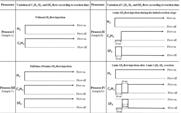
Figure 1. Different reaction processes: process I (sample A): continual H
2+C
2H
2flow (90 min), process II (sample B): H
2+SF
6flow (1 min)→H
2+C
2H
2flow (89 min), process III (sample C): continual H
2+C
2H
2+SF
6flow (90 min), process IV (sample D): H
2+C
2H
2flow (1 min)→H
2+SF
6flow (1 min)→H
2+C
2H
2flow (88 min).
Among the various techniques to synthesize carbon coils, thermal chemical vapor deposition (TCVD) technique using the metal catalyst has been more noticed because of its relative inexpensive and applicable feature. The mainly used metal-based catalysts for carbon coils in TCVD were Fe, Co, Ni or their organic compounds [13-15]. For incorporated additives, meanwhile, a trace of sulfur-related spe- cies [16-18] was regarded as promising additives for the formation of carbon coils. In general sulfur- related species are very hazardous for environment and inevitably damage the health of the people in surroundings. So, it should be indispensible to reduce the use of these materials in the synthesis of carbon coils as possible as one can.
To do this, in this work, we chose SF
6as a sulfur species because it was known as a relatively safe material among the materials containing sulfur species. Furthermore, we tried to reduce the amount of the used SF
6gas by shortening the injection time
as low as 1 min. In this work, therefore, we varied the injection starting point of a short time (1 min) SF
6gas flow (1 min-SF
6flow). The variation of the as-grown carbon coils characteristics, namely the formation density and the geometry, according to the injection starting point of a 1 min-SF
6flow was examined and discussed.
II. Experiments
The SiO
2substrates in this work were prepared by the thermal oxidation of the 2.0×2.0 cm
2p-type Si (100) substrates. The thickness of silicon oxide (SiO
2) layer on Si substrate was estimated about 300 nm. To form Ni catalyst layer, a 0.1 mg Ni powder (99.7 %) was evaporated for 1 min on the substrate using thermal evaporator. The estimated Ni catalyst layer on the substrate was about 400 nm.
For carbon coils deposition, thermal chemical vapor
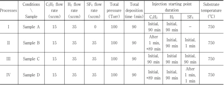
Table 1. Experimental conditions for the deposition of carbon coils on the substrates for samples A∼D.
Processes
Conditions
∖ Sample
C
2H
2flow rate (sccm)
H
2flow rate (sccm)
SF
6flow rate (sccm)
Total pressure
(Torr)
Total deposition time (min)
Injection starting point duration
Substrate temperature
(
oC) C
2H
2H
2SF
6I Sample A 15 35 0 100 90 Initial,
90 min
Initial,
90 min - 750
II Sample B 15 35 35 100 90
After 1 min,
*89 min
Initial, 90 min
Initial,
1 min 750
III Sample C 15 35 35 100 90 Initial,
90 min
Initial 90 min
Initial,
90 min 750
IV Sample D 15 35 35 100 90 Initial,
*89 min
Initial, 90 min
After 1 min,
1 min
750
*In process IV (sample D) case, C
2H
2flow was intermitted for 1 min after 1 min C
2H
2+H
2reaction.
deposition system was employed. C
2H
2and H
2were used as source gases. SF
6was injected for a relatively short time (1 min). Total flow rate was fixed at 50 standard cm
3per minute (sccm). According to the different reaction processes, the flows of source gases were as follows, namely
process I: continual H
2+C
2H
2flow (90 min),
process II: H
2+SF
6flow (1 min) → H
2+C
2H
2flow (89 min),
process III: continual H
2+C
2H
2flow+SF
6flow (90 min),
process IV: H
2+C
2H
2flow (1 min) → H
2+SF
6flow (1 min) → H
2+C
2H
2flow (88 min).
Carbon species to form carbon coils are generated from H
2+C
2H
2flow (C
2H
2flow on). On the contrary, H
2+SF
6flow (C
2H
2flow off) may etch carbon compo- nents. Fig. 1 shows the detailed manipulation of these gases flows according to the processes.
We fixed H
2flow rate, C
2H
2flow rate, SF
6flow rate and total reaction time as 35 sccm, 15 sccm, 35 sccm and 90 min, respectively. The detailed reaction conditions according to the different processes with samples were shown in Table 1.
Detailed morphologies of carbon coils-deposited substrates were investigated by using field emission scanning electron microscopy (FESEM).
III. Results and Discussion
Fig. 2 shows FESEM images showing the surface morphologies of samples according to the processes (processes I ∼IV, samples A∼D). As shown in Fig.
2(a), carbon nanofilaments-related materials could be developed on the surface of sample without SF
6incorporation case (sample A). The embryo for carbon nanofilaments formation and the immatured carbon nanofilaments could be well observed as shown in high-magnified FESEM images (Fig. 3(a)).
Fig. 2(b) shows FESEM images showing the surface
morphology for sample with 1 min-SF
6flow injection
during the initial reaction stage case (sample B). In
this case, however, the dominant formation of
nano-sized wave-like coil types could be clearly
observed (compare Fig. 3(a) with 3(b)). Occasionally,
a couple of micro-sized carbon coils such as linear
tub (LT), micro-sized coil (MC) could be well
observed around the center position of sample B as
shown in Fig. 4(a) and 4(b). Diameters of the micro-
sized carbon coils and the individual carbon nano-
filaments are in the range of several micrometers and
a few hundred nanometers, respectively. The length
range of the coil are in the range between a few
micrometers and a few tens micrometers. In general,
Figure 4. FESEM images of the carbon coils-deposited substrate for sample B (a) around the center position on the substrate and (b) its magnified image. Occasionally, a couple of micro-sized carbon coils could be observed on the surface of the substrate. Fig. 4(c) shows the generally accepted four geometrical categories of carbon coils, namely linear tub (LT), micro-sized coil (MC), nano-sized coil (NC), and wave-like nano-sized coil (WNC).
Figure 2. FESEM images of carbon coils-related materials-deposited substrates for (a) sample A, (b) sample B, (c) sample C and (d) sample D.
Figure 3. High-magnified FESEM images of carbon coils-related materials-deposited substra- tes for (a) sample A, (b) sample B, (c) sample C and (d) sample D.
many types of carbon coils-related geometries could be formed, so they could be usually classified into four geometrical categories, namely linear tub (LT), micro-sized coil (MC), nano-sized coil (NC), and wave-like nano-sized coil (WNC) as shown in Fig.
4(c). Among many types of carbon coils-related geometries, wave-like nano-sized coil (WNC) could be mostly observed on sample B as shown in Fig. 3(b).
To figure out the difference between a 1 min-SF
6flow case and a full time (90 min) SF
6flow case, the morphologies of sample (process III, sample C) com- pleting full time (90 min) incorporation of SF
6flow were examined. As shown in Fig. 2(c) and 3(c), vari-
ous types of carbon coils-related geometries such as LT, MC, NC and WNC could be well observed. This result reveals that a full time SF
6flow injection can ’t limit the geometries of carbon coils related materials.
To know the effect of injecton starting point of 1 min-SF
6flow, we set back the injecting of 1 min-SF
6flow by 1 min carbon coils synthesis reaction like process IV (sample D), namely H
2+C
2H
2flow (1 min)
→ H
2+SF
6flow (1 min) → H
2+C
2H
2flow (88 min). As shown in Fig. 3(d), various types of carbon coils- related geometries such as LT, MC, NC and WNC could be well observed like a full time (90 min) SF
6flow case (process III, sample C). Based on the results
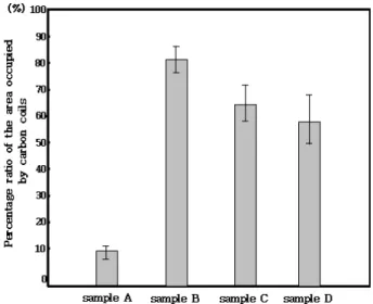
Figure 5. The occupied areas by various types carbon coils according to the (a) process I (sample A), (b) process II (sample B), (c) process III (sample C) and (d) process IV (sample D).
It was measured under the assumption of monolayer-grown carbon coils formation on the substrate.
from Fig. 2 and 3, we confirm that even a short time (1-min) SF
6flow injection could change the geometry of carbon-coils related materials. Furthermore, the injection starting point of 1 min-SF
6flow would be very important to limit the geometries of carbon coils related materials.
Carbon coils formation densities were mainly measured using several 10 k magnified FESEM ima- ges. For objectively measuring carbon coils formation density, image analyzing method has been developed by placing square-graphed transparent paper onto the enlarged copies of FESEM images. Under the assumption of monolayer-grown carbon coils forma- tion on the substrate, the occupied areas by various type carbon coils according to the processes were measured as shown in Fig. 5. The y-axis represents the percentage ratio of the area occupied by carbon coils-related materials. The analysis showed that the average occupied area by carbon coils-related mater- ials of process II is higher than that of any other process.
Based on the results shown in Fig. 2 ∼5, we pro- pose that 1 min-SF
6flow injection during the initial reaction stage (process II, sample B) could give rise to the limitation of the geometry for a dominant WNC type as well as the enhancement of carbon coils- related materials formation density. However, a con- tinuous injecting of SF
6gas flow or a delayed injec- ting of SF
6gas flow can deteriorate the limitation of the geometries. The study on the exact causes and the detailed mechanism for developing the contro- lled-geometry carbon coils by 1 min-SF
6flow injec- tion during the initial reaction stage is underway.
IV. Conclusions
The carbon coils geometry limitation from various types to the dominant formation of nano-sized coil- like type could be achieved by 1 min-SF
6flow injec-
tion during the initial reaction. In addition, the SF
6incorporation during the initial reaction could pro- mote the formation density of carbon coils-related materials. It confirms that even a short time (1-min) SF
6flow injection could change the geometry of carbon-coils related materials. Furthermore, the injection starting point of 1 min-SF
6flow would be very important to limit the carbon coils related geometries.
References
[1] W. R. Davies, R. J. Slawson, and G. R. Rigby, Nature 171, 756 (1953).
[2] R. T. K. Baker, Carbon 27, 315 (1989).
[3] L. J. Pan, T. Hayashida, M. Zhang, and Y.
Nakayama, Jpn. J. Appl. Phys. 40, L235 (2001).
[4] S. Amelinckx, X. B. Zhang, D. Bernaerts, X. F.
Zhang, V. Ivanov, and J. B. Nagy, Science 265, 635 (1994).
[5] A. Fonseca, K. Hernadi, J. B. Nagy, Ph. Lambin,
and A. Lucas, Carbon 33, 1759 (1995).
[6] S. Ihara and S. Itoh, Carbon 33, 931 (1995).
[7] K. Akagi, R. Tamura, and M. Tsukada, Phys. Rev.
Lett. 74, 2307 (1995).
[8] K. D. Kim and S. H. Kim, J. Korean Vacuum Soc.
18, 481 (2009).
[9] Y. Song and S. J. Kang, J. Korean Vacuum Soc.
18, 488 (2009).
[10] A. Volodin, D. Buntinx, M. A. Ahlskog, A.
Fonseca, J. B. Nagy, and C. V. Haesendonck, Nano Lett. 4. 1775 (2004).
[11] A. Szabó, A. Fonseca, J. B. Nagy, Ph. Lambin, and L.P. Biró, Carbon 43, 1628 (2005).
[12] L. S. Schadler, S. C. Giannaris, and P. M. Ajayan, Appl. Phys. Lett. 73, 3842 (1998).
[13] V. Ivanov, J. B. Nagy, Ph. Lambin, A. A. Lucas, X. B. Zhang, X. F. Zhang, D. Bernaerts, G.
Vantendeloo, S. Amelinckx, and J. Vanlanduyt, Chem. Phys. Lett. 223, 329 (1994).
[14] M. Lu, H. L. Li, and K. T. J. Lau, Phys. Chem.
B 108, 6186 (2004).
[15] C. J. Su, D. W. Hwang, S. H. Lin, B. Y. Jin, and L. P. Hwang, Phys. Chem. Commun. 5, 34 (2002).
[16] S. Motojima, Y. Itoh, S. Asakura, and H. Iwanaga, J. Mater. Sci. 30, 5049 (1995).
[17] X. Chen and S. Motojima, J. Mater. Sci. 34, 5519 (1999).
[18] S. Motojima, S. Asakura, T. Kasemura, S. Takeu-
chi, and H. Iwanaga, Carbon 34, 289 (1996).
육불화황 기체의 주입단계에 따른 탄소코일 기하구조의 제약
김성훈*