A Design of Software Receiver for GNSS Signal Processing
Seung Hyun Choi, Jae Hyun Kim, Cheon Sig Shin, Sang Uk Lee, Jae Hoon Kim
요 약
최근들어 하드웨어방식의 GPS 수신기를 소프트웨어 방식의 Software-Defined Radio(SDR)기법으로 구성하 는 연구가 활발히 진행되고 있다. 이러한 소프트웨어 기반의 GPS 수신기는 기존의 하드웨어 방식으로 처리하 는 신호획득부와 추적부를 마이크로 프로세서를 통해 소프트웨어 기법으로 처리하는 것을 말한다. 본 논문에서 는 이러한 소프트웨어 기법을 이용하여 GPS 수신기를 설계하며 PC 기반에서 시뮬레이션을 통해 신호획득부, 추적부, 메시지 복조부를 설계하고 검증한다. 또한 의사거리 오차를 도출하기 위하여 신호 획득부와 추적부에 대해 효율적인 알고리즘을 제안하고 최종적으로L1 주파수대역의 여러 위성을 통해 수신된 채널간의 상대적 지 연을 통해 의사거리를 계산한다. 본 논문에서 제시된 수신기기법은 향후 개발목표인 GPS/Galileo 복합시스템의 개발요소에 포함될 것이며 규격 및 성능을 검증할 방법을 제시할 뿐만 아니라 다양한 디버깅 환경을 제공함으 로써 개발단계에 매우 유용하게 적용될 것이다.
ABSTRACT
Recently, the research of GPS receiver which uses the Software-Defined Radio(SDR) technique is being actively proceeded instead of traditional hardware-based receiver. The software-based GPS receiver indicates that the signal acquisition and tracking treated by the hardware-based platform are processed as the software technique through a microprocessor. In this paper, GPS software receiver is designed by using SDR technique and then the signal acquisition, tracking, and the navigation message decoding parts are verified through the PC-based simulation. Moreover, the efficient algorithms are developed about the signal acquisition and tracking parts in order to obtain the accurate pseudorange. Finally, the pseudorange is calculated through the relative channel delay received through the different satellite of L1 frequency band. GPS software receiver proposed in this paper will be included in the element of GPS/Galileo complex system of development target and will provide not only the method that verifies the performance for Galileo Sensor Station standard but also usability by providing various debugging environments.
TKey Words : TSoftware Receiver, GPS, Galileo, Signal Processing, Navigation, GNSST
T
I
T. Introduction
The Global Navigation Satellite System (GNSS) benefits civilian societies in many aspects such as Geodesy, Surveying, its and Personal Navigation. It is expected that the application of GNSS will be the combination of many navigation system, especially GPS and Galileo system to enhance positioning accuracy and service coverage.[1] We are researching the GPS and Galileo complex system and our purpose of development is to implement GPS and Galileo Senor station. In this paper, the design of receiver is a software-defined radio(SDR) approach. The first step in the receiver processing is a RF Digital Front-End (DFE). The digitized samples are processed by using digital acquisition block with the C/A and digitally mix the result to the baseband, using a parallel code phase search to
remove the effect of the Doppler and receiver coarse frequency offset. And then the next correlator engine takes as coarse synchronized IF sample data. The standard correlator is early-late- prompt configuration, where the user can select predefined correlator chip spacing. All prompt correlator values are passed GPS demodulation such as bit synchronization, parity check, frame synchronization. By using synchronization bit, pseudorange can be calculated. In this paper we give a general overview of our signal processing and show the simulation results obtained the real GPS IF data. [2]
In next section, we introduce the acquisition of GPS multi-channel to estimate coarse carrier phase and code phase. Section 3 illustrates the configuration of tracking and Section 4 presents demodulation algorithm. Finally we draw the conclusion in Section 5.
* Electronics and Telecommunications Research Institute(ETRI) Sattelite Ground Control Technology Team 161 Gajeong-dong, Yuseong-gu, Daejeon, KOREA, 305-700 Email: [email protected], HTU[email protected]UTH
2. Signal Acquisition
GPS signal of open service is transmitted at 1.5 GHz and RF front-end device down converts from raw signal to lower frequency. This frequency data is called Intermediate Frequency(IF). The signal is digitized(A/D conversion) at bit resolution.
The first task of baseband algorithm in the S/W receiver is to fine a rough estimate of the PRN code phase offset and carrier frequency through the digitized IF signal. This information is used to track the signal and demodulate the navigation data. [3]
In the method of the signal acquisition, we use parallel code space search that is suitable for the S/W receiver and improve the TTFF and reduce the computational complexity. The parallel code search algorithm obtains the correlation function value about all combinations between the replica signal sample and the digitized IF signal sample by using DFT. Instead of multiplying the input signal with a PRN code with 1023 different code phases as done in the serial search acquisition method, it is more convenient to make a circular cross correlation between the IF digitized input and local PRN code.
For a stationary receiver, Doppler frequency shift is around ± 5 kHz . If the receiver is used in a high-speed vehicle, it is reasonable to assume that the maximum Doppler shift ± 10 kHz . [4][5]
Figure.1 shows the acquisition flow diagram from the digitized IF input data. The acquisition results represent the code phase (beginning of C/A code) and carrier frequency.
TFigure 1. Signal Acquisition Flow diagram
3. Signal Tracking
T
Acquisition results are handed over to the tracking loops, the function of which are to track the variations in the carrier Doppler and code offset. In this paper, the tracking module includes following function and
Tone of these four
configurations can be possible for GPS and Galileo signal processing.
y Tracking of data channel with or without sub- carrier
y Tracking of two channels(given pilot) with or without sub-carrier
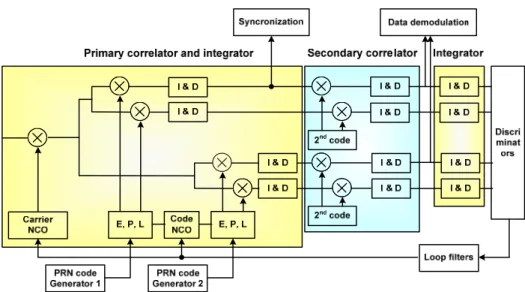
The modernized GPS and Galileo signal includes the pilot channel, which has to be processed for the better performance. But the tracking module of GPS L1 doesn’t need a part of processing pilot. The tracking module consists of the following sets:
Local code generators : A code of GNSS signal is generated and stored in the buffer connecting with the correlator integrator block.
And it is necessary that the size of the buffer be equal to the length of the code.
Primary correlator and integrator: The local code is fixed on the value corresponding to the estimated delay and the correlation is performed until the end of the primary code. This correlation is not carried out over a complete length of code because of the initial delay. It is decided "to throw"
this first correlation and to transmit to the loops only correlations over a complete length of code.
The carrier NCO makes it possible to generate the estimated phase whose complex combined exponential is applied to the entering signal. The command of the NCO corresponds to the output of the loop filter on the carrier (PLL or FPLL or FLL). The correspondence between the state of the NCO and the value of the cosine and sine used for the multiplication by the complex exponential is performed via lookup tables. At the initialization, the tables of sine and cosine are created according to the resolution selected for the phase (typically 16 bits).
The code NCO makes it possible to produce the code at the frequency as follows: K*F
BcB+ NCO command. The command corresponds to the output of the DLL loop filter.
Table 1. NCO configuration: BPSK, BOC(M, N)
No sub-carrier K=1 BOCBsinB K=2*M/N BOCBcosB K=2*[2*M/N]
BCS K=5
T
The resolution N of the NCO is a parameter, it is
to the maximum equal to 64 bits and must be
higher or equal to 48 bits to have good
performances. The NCO takes values between 0
and 2N-1, the increment is calculated
Tas follows:
2 *
N outs
Increment F
= F
F
BoutBis the output frequency of the NCO (F
Bout B= K*F
Bc B+ NCO command), F
BsBis the frequency of the NCO, equal to the sampling rate of the receiver.
Discriminator: First, The discriminator block includes the DLL, PLL and FLL. After calculation, block combines the values of the discriminators if there is a tracking on two channels. The discriminators are implemented as follows:
Table 2. Various Discriminators
DLL Dot product
PLL Atan, Atan2
FLL Differential Atan
In the case of signal with pilot and data channel, there are two possibilities. That’s the tracking only on pilot channel or tracking on pilot and data channel. In the first case, the output of the combined discriminators is equal to the discriminators of pilot channel. In the second case, the discriminators of both channels are combined by using weighting coefficients.
4. Signal demodulation
We use I/Q demodulation in all of the standard
tracking loops. This Demodulation block must decode the navigation data stream from tracking result. The bits are clearly visible in the inphase channel of the tracking loop.
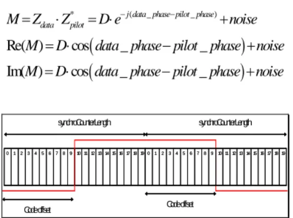
Synchronization: Correlator outputs need to be synchronized with the transition bits and the beginning of the secondary code. There are two types of synchronization by signal property. When the signal is composed of a secondary code, acquisition of the secondary codes is performed.
If the signal contains only data, block transmits the offset to the controller.
Data demodulation: Data demodulation integrates the values over the duration of a bit and determines from the sign of the sum if the data is 0 or 1.
From the integrated value, the determination of the corresponding bit of data is different according to whether a channel or two channels are tracked:
The complex values of the data and pilot channel accumulator are:
( _ )
( _ )
j data phase
data data
j pilot phase
pilot pilot
Z D e Noise
Z e Noise
θ
θ +
+
= ⋅ +
= +
By carrying out the combined complex product of Z
BdataBand Z
BpilotB, the value of the data can be obtained:
Figure 2. Tracking Architecture
( )
( )
* ( _ _ )
Re( ) cos _ _
Im( ) cos _ _
j data phase pilot phase data pilot
M Z Z D e noise
M D data phase pilot phase noise M D data phase pilot phase noise
− −
= ⋅ = ⋅ +
= ⋅ − +
= ⋅ − +
synchroCounterLength
Code offset
19 18 17 16 15 14 13 12 11 10 9 8 7 6 5 4 3 2 1
012345678910111213141516171819 0
19 18 17 16 15 14 13 12 11 10 9 8 7 6 5 4 3 2 1
012345678910111213141516171819 0
synchroCounterLength
Code offset
Figure 3. Bit Synchronization of the GPS L1 signal
5. Conclusions
In this paper, we introduced a S/W receiver architecture for signal processing of GPS and Galileo channel. This software-defined radio offers more significant advantages than traditional hardware design due to the flexibility and complexity. Therefore the hardware GNSS receiver unit of our target in the future will be developed based on this software receiver designed in this paper. In the GNSS signal, the proposed software receiver can find the signal acquisition and signal tracking for the multi- channel. By using the parallel code searching algorithm, the signal acquisition algorithm could do the fast and exact signal acquisition with a few data. Moreover, by using the fine acquisition, DLL and PLL could be finely tracked. In this S/W receiver architecture, acquisition could be complete and the acquired signal is successfully tracked by tracking algorithm of DLL, PLL. We presents the tracking architecture for not only GPS L1 channel but also other channels.
In conclusions, the proposed software receiver of multi-channel can simply modify the structure with flexibility and prove the possibility of the GNSS receiver which will be developed in the future.
Acknowledgment
This work was supported by the IT R&D program of MIC/IITA. [
T2007-S-301-01
T, Develop- ment of Global Navigation Satellite System Ground Station and Search And Rescue Beacon Technologies]
Reference
[1] Dinesh Manadhar, Ryosuke Shibasaki, Software-Based GPS Receiver: A research and Simulation tool for Global Navigation Satellite system
[2] K. Borre, D. M. Akos, N. Bertelsen, P. Rinder, S. H. Jensen, “A Software-Defined GPS and Galileo Receiver,” Birkhauser Boston, 2007.
[3] Jong-Hoon Won, Thomas Pany, Gunter W.Hein, GNSS Software Defined Radio; Real Receiver or Just a Tool for Expert
[4] Van Nee, J.R. & Coenen, J.R.M., “New Fast GPS Code-Acquisition Technique Using FFT,”
Electronics Letters, Vol.27.2, Jan., 1991.
[5] Manandhar, D., Y. Suh, R. Shibasaki, “GPS Signal Acquisition and Tracking – An Approach towards Development of Software-based GPS Receiver,” Technical Report of IEICE, ITS2004, July 16, 2004
[6] J. Bao and Y. Tsui, “Fundamentals of Global Positioning System Receivers A Software Approach,” Willey, second edition, 2005.
[7] P.-L Normark, C. Stahlberg, “Hybrid GPS/Galileo Real Time Software Receiver,”
Proceedings of ION GNSS 2005, Long Beach, Sept., 2005
[8] N. Bertelsen, K. Borre, P. Rinder, “THE GPS CODE SOFTWARE RECEIVER AT AALBORG UNIVERSITY” 2nd ESA Workshop on Satellite Navigation. Navitech 2004 Proceedings, pp.
373-380, 2004.
[9] Lei Dong, et. al., “Implementation and verification of a Software-based IF GPS Signal Simulator,” National Technical Meeting, Institute of Nav., San Diego, Jan. 26~28, 2004.
[10] Kenn G, Alison B, “Architecture and performance Testing of a Software GPS Receiver for Space-based Applications,”
Proceedings of IEEE, March, 2004
U