SGR에서 신호처리과정의 분석과 시뮬레이션
장위*․서희종**
Analysis and Simulation of Signal Acquisition of GPS Software Receiver
Wei Zhang
*․Hee-jong Suh
**요 약
본 논문에서는 SGR(software-based Global Positioning System receiver)에서 GPS(Global Positioning System)의 자료처리과정을 분석하기 위해서, GPS 신호의 수신방법을 심도있게 분석했다. 그리고 이 처리과정 을 Matlab를 사용해서 모의실험을 했다. 실험결과, 이 분석방법의 타당성을 찾을 수 있었고, 이 실험은 실제 환경조건에서와 일치함을 확인할 수 있었다. 또 SGR의 성능을 향상시키기 위해서는 수신기의 성능을 향상시 켜야 한다는 사실을 확인 할 수 있었는데, 동조되는 최적의 주파수는 수십 Hertz내에서 위상을 비교해서 찾을 수 있었다.
ABSTRACT
In this paper, for a software-based Global Positioning System receiver (SGR), the principle capturing Global Positioning System (GPS) signal is researched extensively in order to analyze the processing of the GPS raw data signal at the lowest level, and the process of capturing the GPS signal was simulated by Matlab. The simulation results show the accuracy and the feasibility of this method, which is comparable to study under a true environment. We know that the improvement of the receiving facilities is of very vital significance to the performance of this system, and the fine frequency can be found through comparing phases within a few tens of Hertz.
키워드
GPS, Software GPS, Acquisition
* 북경석유화학원 정보공과대학([email protected]) ** 전남대학교 전자통신공학과([email protected])
접수일자 : 2010. 12. 12 심사(수정)일자 : 2011. 01. 17 게재확정일자 : 2011. 02. 09
I. INTRODUCTION
The Global Positioning System (GPS) has already been used widely in both the civilian and the military community for positioning, navigation, timing and other position related applications. The system has already proved its reliability, availability and good accuracy for many applications [1]. The GPS is a satellite-based navigation system. It is
based on the computation of range from the
receiver to multiple satellites by multiplying the
time delay that a GPS signal needs to travel from
the satellites to the receiver by the velocity of
light. To detect the presence of the signal, an
acquisition method must be used, and the
information in the GPS signal is tracked and
decoded. Once the signal is detected, the necessary
parameters must be obtained and passed to a
tracking program. By the tracking program, information, such as the navigation data, can be obtained. Then the acquisition method must search over a frequency range of ±10 kHz to cover all of the expected Doppler frequency range shifts needed for high-speed aircraft. And to accomplish the search in a short time, the bandwidth of the searching program cannot be very narrow.
When processing the signal acquisition in GPS, a two-dimensional (code and frequency) search is adopted. It is for synchronizing the GPS receiver replica code and the carrier frequency [3]. Usually, coarse acquisition (C/A) code can be acquired quickly and easily, and is used as a hand-over for P-code acquisition [2]. Using a narrow bandwidth for the search means taking many steps to cover the desired frequency range and so it is time-consuming. A search using a wide bandwidth filter will provide relatively poor sensitivity. On the other hand, the tracking method has a very narrow band width; thus a high sensitivity can be achieved [4].
The modern standard GPS receivers are commonly based on ASIC for signal processing.
The main strengths of using ASIC for signal processing include its speed and sensitiveness.
However, the downside is the cost of re-designing, and it is unable to re-programmed. Then, the GPS software receiver, which is different from the ordinary receiver, performs all the operations in a programmable microprocessor, making the system highly flexible. So we contrapose the actuality of mobile communication and put forward a newly defined wireless communication system called Software based GPS Receiver(SGR). It is the third transform in the wireless communication after simulation to digital and immobility to mobile.
In this paper, we analyze the processing of the GPS raw data signal at the lowest level in a software-based Global Positioning System receiver (SGR), we simulate the process of capturing the
GPS signal using Mathlab. Our method is equivalent to studies done under a true environment; we confirmed the accuracy and feasibility of this method. With this simulation we reconfirmed that the improvement of the receiving facilities is of very vital significance in the performance of this system.
This paper is organized as follows; In Section II, the C/A Code Signals acquisition methods are introduced. In Section III, the GPS signal simulation and implementation based on Mathlab is found. The conclusions are given in Section IV, and the references follow.
II. THE ACQUISITION METHODS
The GPS signal is the modulated signal of the C/A code and the navigation message. The navigation message can be obtained from the GPS signal, by removing the carrier wave and C/A code through demodulation and de-spreading. After the demodulation and de-spreading of the signal, the resultant navigation message may include some noise. These navigation messages are then interpreted in accordance with the definitions or coding scheme provided in the GPS interface control document (ICD) [1]. One common way to start an acquisition program is to search for satellites that are visible to the receiver. If the rough location (say Dayton, Ohio, U.S.A.) and the approximate time of day are known, information is available on which satellites are available, such as on some Internet locations, or can be computed from a recently recorded almanac broadcast. When one uses this method for acquisition, only a few satellites (a maximum of 11 satellites if the user is on the earth’s surface) need to be searched for.
However, in the case of a wrong location or time
provided, the time to locate the satellites increases
as the acquisition process may initially search for
the wrong satellites [4].
The other method used to search for the satellites is to perform an acquisition on all the satellites in space; there are 24 satellites. This method assumes that one knows which satellites are in space. When one does not even know which satellites are in space, as in there could be 32 possible satellites, the acquisition must be performed on all of the satellites. This approach is time consuming; a fast acquisition process is always preferred. However, the conventional approach to perform signal acquisition is through the hardware in the time domain. Once the signal is found, the information will immediately passed to the tracking hardware. The acquisition is performed on the input data continuously. In some receivers the acquisition can be performed on many satellites in parallel.
A software-based GPS receiver usually performs the acquisition on a block of data. When the desired signal is found, the information is passed on to the tracking program. If the receiver is working in real time, the tracking program will work on data currently collected by the receiver.
Therefore, there is a time elapse between the data used for acquisition and the data being tracked.
When the acquisition is slow, the time elapse is long so the information passed to the tracking program obtained from old data might be out-of-date. In other words, the receiver may not be able to track the signal. If the software receiver does not operate in real time, the acquisition time is not critical because the tracking program can process stored data. It is desirable to build a real-time receiver; thus, the acquisition speed is very important.
A. The Signal Doppler Estimation
In many GPS receiver applications it is desirable to minimize the time to first fix (TTFF) which is the time from the receiver turn on until the first
navigation solution is obtained. The TTFF can be reduced if the approximate Doppler shifts of the visible satellite singles are known. This permits the receiver to establish a frequency search pattern in which the most likely frequencies of reception are searched first. The expected Doppler shifts can be calculated from knowledge of the approximate position, the approximate time, and valid almanac data. The greatest benefit is obtained when the receiver has a reasonably accurate clock reference oscillator.
However, once the first satellite signal is found, a fairly good estimate of the receiver clock frequency error can be determined by comparing the predicted Doppler shift with measured Doppler shifts. This error can be subtracted out while searching out the frequencies of the remaining satellites, thereby significantly reducing the range of frequencies that need to be searched [5].
B. The GPS Signal Frequency Characteristics, Modulation Methods and their Characteristics
The basic idea of the acquisition is to dispread the input signal and find the carrier frequency [4].
Fig. 1 illustrates a continuous wave signal by multiplying the incoming signal with a perfectly aligned locally generated PRN sequence. Of course, this only happens when the locally generated PRN code is perfectly aligned with the code in the incoming signal. If the incoming signal contains signal components from other satellites, these components will be minimized as a result of the cross-correlation properties of the PRN sequences.
In parallel frequency space search acquisition, the
upper signal in Fig. 1 is the input to the Fourier
transform function. With a perfectly aligned PRN
code, the output of the Fourier transform will show
a distinct peak in magnitude. The peak will be
located at the frequency index corresponding to the
frequency of the continuous-wave signal and
therefore the frequency of the carrier wave signal.
The accuracy of the determined frequency depends on the length of the DFT. The length corresponds to the number of samples in the analyzed data.
When 1 ms of data is analyzed, the number of samples is found to be 1/1000 of the sampling frequency. In other words, if the sampling frequency is fs=10 MHz, the number of samples is N=10,000. In Fig. 1(a) the PRN code is modulated onto the carrier wave. Fig. 1(b) is a perfectly aligned PRN sequence. In Fig. 1(c) we recover the continuous wave after multiplying the incoming signal with the perfectly aligned PRN sequence.
Fig. 1 The PRN code demodulation (a) the incoming signal, (b) the local PRN code, and
(c) the result of multiplication.
The code tracking is very often implemented as a delay lock loop (DLL) where three local codes (replicas) are generated and correlated with the incoming signal. These three replicas are referred to as the early, prompt, and late replica. The three codes are often separated by 12 chips. The other component of the tracking is the carrier wave tracking. This tracking can be done in two ways, either by tracking the phase of the signal or by tracking the frequency. The tracking runs continuously to follow the changes in frequency as a function of time. If the receiver loses track of one of the satellites, a new acquisition must be performed on that particular satellite.
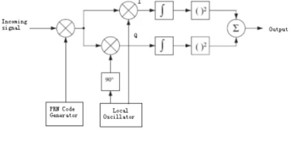
Serial search acquisition is one of the first methods used for acquisition in a CDMA system.
Fig. 2 is a block diagram of the serial search algorithm. The algorithm is based on the multiplication of the locally generated PRN code sequences and the locally generated carrier signals.
The PRN generator generates a PRN sequence corresponding to a specific satellite.
Fig. 2 The block diagram of the serial search algorithm.
As seen in Fig. 2, the algorithm is based on the multiplication of the locally generated PRN code sequences and locally generated carrier signals. The generated sequence has a certain code phase, from 1 to 1023 chips. The incoming signal is initially multiplied by this locally generated PRN sequence.
After the multiplication with the PRN sequence, the signal is multiplied with a locally generated carrier signal. The multiplication with the carrier signal generates the I signal, and the multiplication with a 90o phase shifted version of the carrier signal generates the Q signal. The I and Q signals are integrated over a certain time period 4 and finally squared and added together. Ideally, the signal power should be located in the I part of the signal, as the C/A code is only modulated onto that.
However, in this case the I signal generated at the
satellite does not necessarily correspond to the
demodulated I. This is because the signal phase is
unknown. So to be certain that the signal is
detected, it is necessary to investigate both the I
and Q signals. The output is the correlation value
between the incoming signal and the locally generated signal. If a predefined threshold is exceeded, the frequency and code phase parameters are correct, and the parameters can be passed onto the tracking algorithms. The serial search algorithm makes two different sweeps: A frequency sweep over all possible carrier frequencies of IF±10 kHz in steps of 500Hz and a code phase sweep over all 1023 different code phases. All in all, this sums up to a total of: 1,023⨯(2⨯10,000/500 + 1)=1,023⨯
41=41,943.
Obviously, this is a very large number of combinations. This exhausting search routine also tends to be the main weakness of the serial search acquisition method.
The serial search acquisition method is a very time-consuming procedure that searches sequentially through all the possible values of the two frequency and code phase parameters. If any of the two parameters could be eliminated from the search procedure or possibly implemented in parallel, the performance of the procedure would increase significantly. This is called a parallel frequency space search acquisition.
Fig. 2 shows that the first task in the serial search acquisition method is to multiply the incoming signal with the locally generated PRN sequence. This, of course, involves the generation of the particular PRN sequence. Instead of generating the PRN sequences every time the algorithm is executed, all possible PRN sequences are generated offline. The 32 different PRN sequences are generated by the PRN generator.
The PRN code generator is implemented using the binary values 0 and 1. However, in the signal processing algorithms it is more convenient to represent the codes with a polar non-return-to-zero representation. With 32 generated PRN sequences, all the possible sequences originating from the GPS satellites are created. However, as mentioned in the theory of serial search acquisition, the method
involves multiplication with all possible shifted versions of the PRN codes. That is, besides saving the 32 possible PRN codes all the possible shifted versions should also be saved. This adds up to a total of 32,736 different PRN codes. To make the multiplication between one of the generated PRN codes and the incoming signal possible, the code has to be sampled with 38.192 MHz, like the received signal. This sampling converts the length of a PRN sequence from 1023 to 38,192.
III. THE GPS SIGNAL SIMULATION AND IMPLEMENTATION
We did the simulations by MATLAB. The data were digitized at 5 MHz. The data references 7 satellites, numbers 6, 10, 17, 23, 24, 26, and 28.
Most of the satellites in the data are reasonably strong and they can be found from 1ms of data.
However, this is a qualitative discussion, because no threshold is used to determine the probability of detection. Satellite 24 is weak; in order to confirm this signal several milliseconds of data need to be added incoherently.
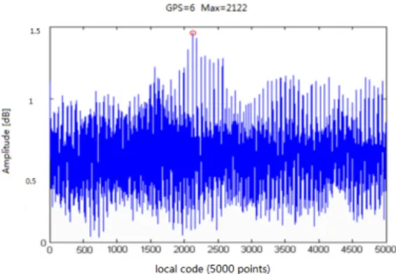
Fig. 3 The beginning of the C/A code of satellite 6.
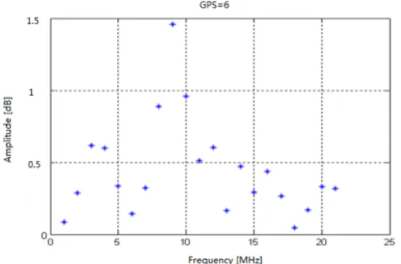
Fig. 4 The frequency component of the dispread signal of satellite 6.
The bandwidth is 2.5 MHz as expected. The spectrum shape resembles the shape of the filter in the RF chain. After the circular correlation, the beginning of the C/A code of satellite 6 is shown in Fig. 3. The beginning of the C/A code is at 2,122.
The amplitudes of the 21 frequency components separated by 1 KHz are shown in Fig. 4.
From Fig. 3 and Fig. 4, one can see that the initial point of the C/A code and the frequency are clearly shown. Since the data are actually collected, the accuracy of the fine frequency is difficult to determine because the Doppler frequency is unknown.
The fine frequency also depends on the frequency accuracy of the local oscillator used in the down conversion and the accuracy of the sampling frequency. One way to get a feeling of the calculated fine frequency accuracy is to use different portions of the data. Six fine frequencies are calculated from different portions of the input data.
The data used are 1-25000, 5001-30001, 10001-35001, 15001-40001, 2001-45001, and 2501- 50001. These data are five milliseconds long and the starting points are shifted by 1 ms. Between any two adjacent data sets four out of the five milliseconds of data are the same. Therefore, the calculated fine frequency should be close. The fine frequency differences between these six sets are − 2.4, 9.0, −8.2, 5.4, and 2.3 Hz. These data are
collected at a stationary set. The frequency change per millisecond should be very small. Thus ,the frequency difference can be considered as the inaccuracy of the acquisition method. When the signal strength changes, the difference of the fine frequency also changes. For a weak signal the frequency difference can be in tens of Hertz, if the same calculation method is used.
The acquisition performed on the weak signal (satellite 24) is shown in Fig. 5 and Fig. 6. From these figures, it is difficult to assess whether the beginning point of the C/A code and the frequency are the correct values. The beginning of the C/A code and the fine frequency can be found by adding more calculations incoherently. The correct results are different from the maximum shown in Fig. 5 and Fig. 6.
Fig. 5 The beginning of the C/A code of satellite 24.
Fig. 6 The frequency component of the dispread signal
of satellite 24.
IV. CONCLUSION
The concept of signal acquisition is discussed in this paper. We have studied the algorithms for acquisition. Study on software-based GPS receivers was the focus of our research, because of their easy reprogramming and flexibility. We knew the sampling of an incoming wide band signal will allow the receiver to capture more navigation signals as compared to other standards. This paper analyzed the different methods of acquisition and the use of simulation software. The simulation results further confirmed the correctness of this method and the feasibility of this simulation platform in a real world environment for further study of the GPS signal. We knew the improvement of the performance of some of the satellite receivers has a very important practical significance. The fine frequency could be found through comparing phases within a few tens of Hertz. Our future work consists of extracting the navigation message from the tracking output and to compute the position of the receiver.
REFERENCES
[1] Dinesh Manandhar, “GPS Signal Acquisition and Tracking An Approach towards development of Software-based GPS Receiver,” IEIC Technical Report (Institute of Electronics, Information and Communication Engineers), Vol. 104; No. 230(ITS2004 7-16);
pp. 51-56, 2004.
[2] C. Yang, “Sequential Block Search for Direct Acquisition of Long Codes under Large Uncertainty,” ION NTM 2001, Long Beach, CA, Jan. pp. 22-24, 2001.
[3] Braasch, M.S.; van Dierendonck, A.J., “GPS receiver architectures and measurements,”
Proceedings of IEEE, vol. 87/1, pp. 48-64, Jan.
1999.
[4] James Bao-Yen Tsui, “Fundamentals of Global Positioning System Receivers - A Software
Approach," John Wiley & Sons Inc, pp.
133-159, 2005.
[5] Mohinder S. Grewal, Lawrence R. Weill, Angus P. Andrews, “Global Positioning Systems, Inertial Navigation, and Integration,”
John Wiley & Sons,pp. 46-47, 2001.
저자 소개
장위(Wei Zhang)
1997년 북경 연합대학교 Techno- logy전공 졸업(공학사)
2010년 전남대학교 대학원 전자통 신공학과 졸업(공학석사)
현재 북경 석유화공학원 교수
※ 관심분야 : 무선통신시스템, 위성통신
서희종(Hee-jong Suh)