소프트웨어 기반의 GPS L1 및 갈릴레오 E1/E5a 신호 처리 구현 및 성능에 관한 연구
A Study on the Implementation and Performance Analysis of Software Based GPS L1 and Galileo E1/E5a Signal Processing
신천식
*
, 이상욱**
, 윤동원*
, 김재훈**
Cheon-Sig Sin
*, Sang-Uk Lee
**, Dong-Won Yoon
*and Jae-Hoon Kim
**요 약
본 논문에서는 위성항법신호감시국용 GPS/갈릴레오 복합 수신기에서의 소프트웨어 기반의 GPS L1 및 갈릴 레오 E1/E5a 신호처리 결과를 기술한다. 성능 검증을 위해 GNSS RF 신호 시뮬레이터 또는 GPS 위성의 실제 신호를 사용하였고, 세부적으로는 광대역 안테나, 112MHz 샘플링 주파수 및 8비트 양자화 레벨을 제공하는 RF/IF 유니트를 이용하여 갈릴레오 시험위성인 지오베-A(GIOVE-A) E1 신호처리를 통해, 갈릴레오 신호처리 를 검증하고, FPGA 기반의 신호처리 보드상에서의 시험결과를 제시한다.
Abstract
In this paper, the key technologies of Navigation receiver for GNSS sensor station are presented as a development result of a GNSS ground station in ETRI. A wide-band antenna and RF/IF components and SW signal processing unit to cover the GPS and Galileo signals for GNSS receiver are developed and its performance is verified by using GPS live signal and GNSS RF signal simulator from SpirentTM. We also gather GIOVE-A signal by using H/W antenna and RF/IF units in IF-level as sampling frequency and bit number, 112MHz and 8bits, respectively by using the developed wide-band antenna and RF/IF components.
Data acquisition is done by using commercial data acquisition device from National Instrument TM. The gathered data is fed into SW receiver to process Galileo E1 to verify Galileo signal processing by Galileo live signal from GIOVE-A.
Key words : Global Navigation Satellite System(GNSS), Navigation Receiver Unit, GPS and Galileo Combined Receiver
* 한양대학교 전자컴퓨터통신 공학과(Department of Electronics Computer Engineering, Hanyang University) ** 한국전자통신연구원 위성관제․항법연구팀(Satellite Control & Navigation Research Team, ETRI)
‧ 제1저자 (First Author) : 신천식 ‧ 투고일자 : 2009년 4월 30일
‧ 심사(수정)일자 : 2009년 5월 1일 (수정일자 : 2009년 6월 15일) ‧ 게재일자 : 2009년 6월 30일
I. Introduction
Recently, satellite navigation system becomes the
most optimal, widely-used means for providing
navigation and positioning services with high precision
for all users at any place all the time.
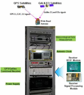
At present, the U.S. Global Positioning System(GPS) and the Russian Global Navigation Satellite System(GLONASS) have been built [1]. The European Union planned to build the Galileo System in 1999. The Galileo System would be put into use by the end of 2008. or so. In addition, other countries such as China, India and Japan are also planning to build their own satellite navigation systems. The positioning, velocity and timing service provided by the satellite navigation systems have been used in many fields. It has great influences on the corresponding industries, technology and people living styles. The satellite navigation has become an important infrastructure just like highways, water providing system and electric system. ETRI involved in developing technologies of related with GNSS ground sensor station from 2007 up to 2010. The system configuration which will be researched and developed by ETRI is shown in figure 1. The main purpose of the GNSS ground sensor station is to develop the key technologies such as high precision receiving function of GPS/Galileo combined receiver unit for a global navigation satellite system. The S/W receiver includes the function of baseband technology in the GNSS sensor station.
Fig. 1. Hardware Configuration of GNSS Sensor Station
The software GPS/Galileo receiver can process wide bandwidth (about the 24 MHz) GPS L1 signal and Galileo E1 signal. All of them are capable of acquiring and tracking four or more satellite signal simultaneously, thus allowing real time positioning with a high performance PC, a prototyping Front End and an analog to digital conversion(ADC) card. The implemented receiver is realized in C code to increase performance for an standard PC running under Windows. Real signals are digitized by a National Instruments(NI) equipment and prototyping ADC card which is connected to a wide bandwidth. In this paper, it would be presented that GPS L5 signal processing results and Galileo E1 signal processing results based on the hardware prototyping which are manufactured to verify the signal acquisition and signal tracking for GPS L5 and Galileo E1 signal.
Ⅱ. GPS/Galileo Combined GNSS Receiver Configuration
GPS and Galileo Combined Receiver consists of RF Front End and Baseband section. The function of RF Front End is to convert RF to Digital information including the IF. The mission of the baseband section is to get signal acquisition and signal tracking including signal demodulation function.
2-1 RF Front End Configuration
For the wide-bandwidth, GPS L5 and Galileo E1 receiver front end, a low -IF architecture has been chosen. Figure 2 shows the functional block diagram of RF front end.
Fig. 2. Functional Block Diagram of RF Front End.
Antenna unit consists of GNSS antenna and low noise amplifier. RF/IF converter unit is composed of diplexer, power divider, and RF/IF converter including AD converter.The antenna and low noise amplifier are operated in the frequency range of 1.16 to 1.61 GHz.
For instance, the antenna unit can receive the minimum signal of -130 dBm from GPS navigation satellites. The antenna has been designed to be operated in the hemispherical coverage. The structure of antenna is a kind of conical spiral antenna as shown in figure 3.
Fig. 3. Antenna Hardware Configuration
RF/IF unit consists of RF/IF converter and AD converter. Each RF/IF converter for every navigation signal band has been designed with the same configuration. The differences as navigation signal band in the configuration are the image filter, SAW filter, and PLL.
2-2 Baseband Configuration
The baseband consists of the signal acquisition part and signal tracking part. The mission of signal acquisition is to determine the visible satellite and coarse values of carrier frequency and code phase of the satellite signals. Code phase of first output is the time alignment of the PRN code in order to generate a local PRN code that is perfectly aligned with the incoming signal. Second output parameter is the carrier frequency, which corresponds to the IF. To consider the Doppler effects, the frequency can deviate up to 5kHz in case of the stationary receiver. The acquisition block consists of the carrier removal, acquisition by FFT and PRN code
generator as shown in figure 4 [2].
Fig. 4. Acquisition Configuration for Signal Processing
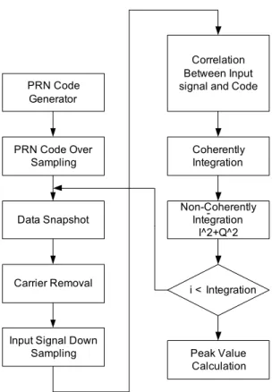
Tracking mode consists of the carrier tracking and code tracking. The code tracking procedure is required to maintain the very high level of synchronization necessary to determine position accurately. To do this, one must generate an error signal to estimate the phase difference between the PRN code in the received signal and locally generate PRN code. The general signal tracking processing flow is shown in figure 5 [3].
Fig. 5. Signal Tracking Configuration for Signal Processing
The tracking is running continuously to follow the
changes in frequency as a function of time. If the
receiver loses track of a satellite, a new acquisition must
be performed for that particular satellite. The sate
machine for signal acquisition of receiver is based on
the figure 6. The signal tracking consists in having fixed
parameters of loops to use the figure 7. By using the
results of code and carrier loop, the bit synchronization
is fitted and data are demodulated.
Data Snapshot PRN Code
Generator
Carrier Removal PRN Code Over
Sampling
Input Signal Down Sampling
i < Integration
Peak Value Calculation Correlation Between Input signal and Code
Coherently Integration
Non-Coherently Integration
I^2+Q^2 -
Fig. 6. Signal Flow Diagram for Signal Acquisition
Doppler
Removal Correlator Sec_
Correlator
DLL_Disc DLL_
LoopFilter Carrier_
Disc
Carrier_
LoopFilter
Calc_
Increment
ACQ_Sync CN0_
Estimator
Bit_Sync Demod
PilotCode Rom
Fig. 7. Signal Flow Diagram for Signal Tracking.
To extract the navigation data, the C/A code and the carrier wave can be removed from the signal, only leaving the navigation data bits after properly tracking the signal. The value of a data bit is found by taking integration over a navigation bit period of 20 msec.
After reading about 30 sec of data, the beginning of a subframe must be found in order to find the time when the data was transmitted from the satellite.
The signal processing board which is based on FPGA(Field Programmable Gate Array) is shown in figure 8.
Fig. 8. Signal Processing Configuration Based on FPGA.
Ⅲ. Simulation and Testing Results
Signal processing is responsible for acquiring and tracking the GPS/Galileo satellites. First, the algorithm performs a search for satellites in view, or, if valid almanac information and approximate receiver position and time are available, estimates which satellites are visible and attempts to acquire them. After acquisition, the code phase and Doppler of each acquired satellite are used to initialize the tracking loops. These loops (carrier and code loops) are updated continuously so that satellite and receiver dynamics can be tracked.
3-1 Signal Acquisition
The function of signal acquisition is to find a roughly estimate value of the PRN code phase offset and carrier frequency. Signal acquisition is essentially a two-dimensional search process in which replica code and replica carriers are aligned with the received signal.
In the method of the signal acquisition, it can largely be
divided into three methods with the serial search,
parallel frequency space search, and the parallel code
space search. It is advantageous to use the parallel code
space search algorithm in order to be suitable for the
S/W receiver, improve the TTFF, and reduce the
computational complexity [4]. The parallel code search
algorithm obtains the correlation function value about all combinations between the replica signal samples and the digitized IF signal samples by using DFT. Instead of multiplying the input signal with a PRN code with 1023 different code phases as done in the serial search acquisition method, it is more convenient to make a circular cross correlation between the IF digitized input and local PRN code. The circular cross correlation function between IF signal and local PN code can be written as
(
*) (
*)
( ) l( ) IF( ) l( ) IF( )
z k
=IDFT R f
×R f
=IDFT R f
×R f
(1)
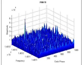
where Rl is discrete Fourier transform of local PN code and RIF is discrete Fourier transform of the IF digitized signal. The carrier value can be found through DFT or FFT and unit of about 10Hz. Since navigation data is 20 ms or 20 C/A code, maximum data length should be 10 ms. Fig. 10 shows the results of signal acquisition for GPS L1 signal. Fig. 11 shows the results of signal acquisition for Glaileo E5a signal.
0 5 10 15 20 25 30
0 1 2 3 4 5 6 7 8 9 10
Acquisition results
PRN number (no bar - SV is not in the acquisition list)
SNR
Not acquired signals Acquired signals
Fig. 9. Signal Acquisition Results of GPS L1 Signal.
Fig. 10. Carrier Frequency and Code Phase Result of GPS L1 Signal.
Fig. 11. Carrier Frequency and Code Phase Result of Galileo E5a Signal.
3-2 Signal Tracking
Signal tracking is the process that a receiver synchronizes the Galileo and GPS signal. Tracking module can configure the loop bandwidth, integration time, early-late chip spacing and correlator's number to use for tracking [5]. Applied parameters such as integration time, discriminator type to get the simulation result are shown in table 1.
The tracking loops consist of a delay lock loop (DLL)
for tracking the code and a phase lock loop (PLL) to
track the carrier. The code tracking block of the S/W
receiver is implemented using the method of Early-Late
code tracking, that involves correlation with three
different generated codes known as the early (E), the prompt (P), and the late (L) codes [6]. To provide an input to the code generator, the outputs of correlators should be combined. To do that, the code phase of the generated PRN code will be properly adjusted.
Table 1. Simulation Conditions for Signal Tracking.
Parameters GPS L1 Signal
Galileo E1
Signal Galileo E5a Coherent Integration
Time 1msec 4msec 4msec
Non-Coherent
Integration No. 1 1 1
Early-Late Chip
Spacing 1 0.2 0.2
Loop Type DLL/PLL DLL/PLL DLL/PLL
DLL Discriminator Type
Nomalized early minus
envelope
Nomalized early minus
envelope
Nomalized early minus
envelope PLL Discriminator
Type Atan Atan Atan
DLL/PLL Filter
Order 2nd /2nd 2nd /2nd 2nd /2nd DLL/PLL Filter BW 5Hz/10 Hz 5Hz/15Hz 5Hz/15Hz
Fig. 12. Tracking Results of GPS L1 Signal.
The input of code generator is computed through normalized early minus late envelope discriminator. The carrier tracking block of the S/W receiver is implemented as a Costas PLL. A PLL measures the carrier phase error and adjusts the frequency of the local oscillator based on that error. The input of local oscillator is computed through arctangent discriminator because of its high accuracy and insensitivity towards
navigation bit transitions. The tracking results of GPS L1 signal are shown in figure 12.
Also the tracking results for Galileo E1 signal are shown in figure 13. Although in case of Galileo E1 there are existed data channel and pilot channel, only the tracking result of data channel is described.
Fig. 13. Tracking Results of Galileo E1 Signal.
Also the tracking results for Galileo E5a signal are shown in figure 14.
(a) Filtered Code Measurement
(b) Filtered Phase Measurement
(c) Pseudorange and Phase Measurement Fig. 14. Tracking Results of Galileo E5a Signal.
IV. Conclusions
In this paper, the wide-band antenna and RF/IF components and SW signal processing unit to cover the GPS and Galileo signals of GNSS receiver for GNSS sensor station was presented. GPS and Galileo receiver architecture and implementation results for the SW signal processing of GPS L1 channel and Galileo E1/E5a channel are presented. By using the FFT algorithm, the signal acquisition algorithm could do the fast and exact signal acquisition with a few data.
Moreover, DLL and PLL could be finely tracked by using the fine acquisition. To get the IF sample data, we
have to use the RF-IF hardware prototype and receive directly the RF signal from GPS and GIOVE-B which is Galileo Test Satellite. The signal processing results by using live GPS and GIOVE-B signal were performed successfully by using prototyped antenna, RF/IF, and baseband.
As a future work, we will make the detailed design document of GNSS ground sensor station and implement the FPGA based hardware GNSS receiver. It can be used for GNSS sensor station in the future.
ACKNOWLEDGMENTS
This work was supported by the IT R&D program of the KCC and the IITA. [2007-S-301-01, Development of GNSS ground station and SAR beacon technologies]
감사의 글
본 논문은 방송통신위원회 및 정보통신연구진흥 원의 IT 연구개발사업 프로그램의 일환으로 수행하 였음.[2007-S301-01, 위성항법지상국 시스템 및 탐색 구조단말기 기술개발]
References
[1] Kaplan, Elliot D., "Understanding GPS: Principles and Applications," Artech House, 2006
[2] Van Nee, J.R. & Coenen, J.R.M., "New Fast GPS Code-Acquisition Technique Using FFT,"
Electronics Letters, Vol.27.2, Jan., 1991
[3] James BAO-YEN TSUI, "Fundamentals of Global Positioning System Receivers A Software Approach.
[4] Manandhar, D., Y. Suh, R. Shibasaki, "GPS Signal Acquisition and Tracking –An Approach towards Development of Software-based GPS Receiver,"
Technical Report of IEICE, ITS2004, July 16, 2004 [5] Cheon Sig SIN, "A Software Receiver Implemenation
for GPS L1 and Galileo E1 Signal", pp. 46-58, Vol
1, ASMS 2008.
[6] K. Borre, D. M. Akos, N. Bertelsen, P. Rinder, S.
H. Jensen, "A Software-Defined GPS and Galileo Receiver," Birkhauser Boston, 2007
신 천 식 (申天植)
1990년 2월 : 한양대학교 전자공학과 (공학사))
2000년 2월 : 충남대학교 전자공학과 (공학석사)
2005년 3월~현재 : 한양대학교 전자컴 퓨터 통신공학과 박사과정
1990년 2월 ~ 현재 :ETRI 책임연구원
관심분야 : 위성항법, 위성항법수신기, 위성통신시스템, 위성궤도주파수
이 상 욱 (李相郁)
1988년 2월 : 연세대학교 천문기상학 과(공학사)
1991년 3월 : Auburn대학교 항공우주 공학과 (공학석사)
1994년 3월 : Auburn 대학교 항공우주 공학과(공학박사)
1993년 3월 ~ 현재 :ETRI 책임연구원 관심분야 : 인공위성시스템, 위성항법
윤 동 원 (尹東源)
1989년 2월 : 한양대학교 전자통신공 학과(공학사)
1992년 2월 : 한양대학교 전자통신공 학과(공학석사)
1995년 8월 : 한양대학교 전자통신공 학과(공학박사)
1995년 3월-1997년 8월 : 동서대학교 전임강사
1997년 9월 ~ 2004년 2월 : 대전대학교 부교수
2004년 3월 ~ 현재 :한양대학교 전자컴퓨터통신공학부 교수
관심분야 :무선통신, 이동통신, 위성 및 우주통신
김 재 훈 (金載勳)
1983년 2월 : 숭실대학교 전자계산학 과(공학사)
1993년 2월 : 숭실대학교 전자계산학 과 (석사)
2001년 9월 : 충북대학교 컴퓨터공학 (박사)
1983년 3월 ~ 현재 : ETRI 팀장/책임연구원
관심분야 : 위성관제, 위성통신 위성항법 및 항법응용