고정밀 위성항법 수신기용 RF 수신단 설계
Design of RF Front-end for High Precision GNSS Receiver
Dong-Pil Chang, In-Bok Yom, Sang-Uk Lee
요 약
본 논문에서는 기존의 GPS 항법 신호와 유럽에서 새롭게 추진되고 있는 갈릴레오 위성 항법 신호를 동시에 수신할 수 있는 광대역 고정밀 위성 항법 수신기의 RF 수신단 장치 설계 및 제작 결과에 대하여 기술하고 있 다. 고정밀 광대역 위성 항법 수신기는 L‐대역 안테나, 항법 신호별 RF/IF 변환부, 그리고 고성능 기저대역 신호 처리부로 구성되어진다. L‐대역 안테나는 1.1GHz~1.6 GHz를 수신할 수 있어야 하며, 항법 위성이 지평선 가까이 에 있을 경우의 항법 신호를 수신할 수 있어야 한다. 갈릴레오 위성 항법 신호는 L1, E5, E6의 서로 다른 대역의 신호를 가지고 있으며, 신호 대역폭이 20MHz 이상으로 기존의 GPS위성 항법 신호보다 광대역이며, 따라서 수신 기의 IF 주파수가 높아지며, 수신기의 처리 속도도 빨라져야 한다. 본 연구에서 개발한 수신기의 RF/IF 변환부는 단일 하향 변환기 구조의 디지털 IF 기술로 설계되었으며, IF 주파수는 위성 항법 신호의 최대 대역폭과 표본화 주 파수 등을 고려하여 140MHz로 설정하였으며, 표본화 주파수는 112MHz로 설정하였다. RF/IF 변환부의 최종 출력 은 디지털 IF 신호로서, IF 신호를 AD 변환기로 처리하여 얻게 된다. 본 연구에서 설계된 위성 항법용 고정밀 수신 기 RF 수신단은 ‐130 dBm의 입력 신호에 대하여 40dB Hz 이상의 C/N0 특성을 가지며, 40dB 이상의 동적 범 위를 갖도록 자동 이득조절 장치가 포함되어 있다.
ABSTRACT
This paper describes the development of RF front‐end equipment of a wide band high precision satellite navigation receiver to be able to receive the currently available GPS navigation signal and the GALILEO navigation signal to be developed in Europe in the near future. The wide band satellite navigation receiver with high precision performance is composed of L‐band antenna, RF/IF converters for multi‐band navigation signals, and high performance baseband processor. The L‐band satellite navigation antenna is able to be received the signals in the range from 1.1 GHz to 1.6 GHz and from the navigation satellite positioned near the horizon. The navigation signal of GALILEO navigation satellite consists of L1, E5, and E6 band with signal bandwidth more than 20 MHz which is wider than GPS signal. Due to the wide band navigation signal, the IF frequency and signal processing speed should be increased. The RF/IF converter has been designed with the single stage downconversion structure, and the IF frequency of 140 MHz has been derived from considering the maximum signal bandwidth and the sampling frequency of 112 MHz to be used in ADC circuit. The final output of RF/IF converter is a digital IF signal which is generated from signal processing of the AD converter from the IF signal. The developed RF front‐end has the C/N0 performance over 40dB‐Hz for the ‐130dBm input signal power and includes the automatic gain control circuits to provide the dynamic range over 40dB.K e y W o r d s : Global Navigation Satellite System, Navigation Receiver, RF Front‐end, Antenna
1 . Introduction
GNSS (Global Navigation Satellite Systems) has already been used and will have an ever increasing influence on our daily life in the future.
On the other hand, in the upcoming years the location of mobile phones or PDAs will become by far the market leader in the area of personal
navigation applications. Due to GPS modernization project by United State and the GALILEO system which will be available around 2010 by European Space Agency (ESA), the applications of GNSS services will be expanded rapidly.
GPS provides the services for public users and military users, and GALILEO system has a plan to provide open service and commercial
* 한국전자통신연구원 광역무선기술연구부([email protected])
※ 본 연구는 정보통신부 및 정보통신연구진흥원의 IT신성장동력핵심기술개발사업의 일환으로 수행한 연구로부터 도출된 것입 니다. [과제관리번호: 2007-S-301-01, 과제명: 위성항법지상국시스템 및 탐색 구조 단말기 기술개발].
service for public users and SOL (Safety of Life) service and public regulated service (PRS) for designated users.
The new European satellite navigation system, named GALILEO, which is now entering the development and validation phase as well as planned improvement of the GPS, will further expand and improve applications for users in many fields by allowing combined use of such system in hybrid receivers.
GNSS sensor station is required to monitor the navigation signals from navigation satellites.
GNSS sensor station is in charge of providing satellite signals in space observables, both for navigation and integrity computation. The GNSS sensor station receives and demodulates the L‐
band signals transmitted by each navigation satellite. GNSS sensor station is composed of receiver chains, signal processors, meteorological station, atomic clock and frequency unit, and monitoring and control unit.
The receiver chain of GNSS sensor station consists of antenna unit including low noise preamplifier and receiver unit including RF/IF conversion block and baseband signal processing block.
The key performances of the receiver chain required for GNSS sensor station are high precision and fast processing time.
The RF front‐end block including antenna unit and RF/IF conversion block affects in the accuracy performance. The SNR and dynamic range of the RF front‐end are important factors related to acquisition time and position accuracy.
This paper describes the satellite navigation signal related to GPS signal and GALILEO signal, and the structure of the GALILEO/GPS hybrid receiver for GNSS sensor station and presents the design and the test results of the RF front‐
end block of the receiver chain.
Ⅱ. Satellite Navigation Signal
A schematic representation of the future GPS/GALILEO L‐band spectrum is shown in Figure 1. GALILEO Satellites will share the L1 band (1575.42MHz) with GPS. The L1 carrier will be modulated by a BOC‐modulated open service signal consisting of a data‐carrying component and a data‐less component (pilot), and by a Public Regulated Service (PRS) signal, using a high‐rate BOC(m,n) modulation. In the E6 band (1278.75 MHz) a BPSK(5) modulated commercial service data/pilot pair will be available together with a BOC modulated PRS signal.
The two other carriers (E5A and E5B) are coherently generated by the satellite. In fact the satellite will use an 8‐QPSK(10) modulation scheme to coherently generated the E5A and E5B signals. This E5A/B signal is modulated a carrier at 1191.795 MHz.
The user can consider the E5A and E5B signals like two I/Q multiplexed BPSK(10) data/pilot signal pairs. The E5B signal has a center frequency of 1207.14 MHz. The center frequency of the E5A signal corresponds exactly to the GPS L5 carrier (1176.45MHz). Also the modulation of the GALILEO E5A signal is similar to the one of GPS L5 signal.
Figure 1. GALILEO/GPS spectrum [4]
The user can consider the E5A and E5B signals like two I/Q multiplexed BPSK(10) data/pilot signal pairs. The E5B signal has a center frequency of 1207.14 MHz. The center frequency of the E5A signal corresponds exactly to the GPS L5 carrier (1176.45MHz). Also the modulation of the GALILEO E5A signal is similar to the one of GPS L5 signal.
As the E5A and E5B signals are coherently generated, they can be tracked as if it was one wideband AltBOC signal with two 20.46 MHz spectral lobes at a spacing of 30 x 1.023 MHz.
The difference with a true BOC is that the two spectral components (E5A and E5B) are modulated by different spreading codes [3][4].
GPS L1 signal is generated by BPSK modulation with the center frequency of 1575.42 MHz. GPS L2 signal has a center frequency of 1227.6 MHz and uses BPSK modulation. GPS L5 signal is a BPSK(10) modulated commercial service data/pilot pair.
The characteristics of GPS and GALILEO
navigation signals are summarized in Table 1.
Many kinds of navigation signals will be available from GPS and GALILEO satellite in near future. Users on the earth can select and use higher quality signals of the received signals when they have a hybrid receiver for GSP and GALILEO signals.
Table 1. Summary of Navigation Signals
Signal
Center Freq.
(MHz)
Mod.
Type
BW (MHz) GPS L1 C/A 1575.42 BPSK 2
GPS L2C 1227.6 BPSK 2 GPS L5 1176.45 BPSK 20 GALILEO L1 1575.42 BOC 25 GALILEO E5A 1176.45 BPSK 20.46
GLILEO E5B 1207.14 BPSK 20.46 GLILEO E6 1278.75 BOC 41 Figure 2 shows an architecture of hybrid receiver to be able to process GPS and GALILEO signals simultaneously.
The receiver consists of antenna unit, RF/IF converter blocks, and baseband processor blocks.
The antenna unit including low noise amplifier has a capability of receiving whole navigation signals in the range from 1.1 GHz to 1.6 GHz. The signals from the antenna unit are divided to five carrier signals by using diplexer and power divider and converted to IF signals through RF/IF converter.
Each IF signal is processed to acquire measurement data in baseband processor block.
The diplexer has a role of dividing low L‐
band frequency near 1.2 GHz and high L‐band frequency near 1.6 GHz with low loss characteristics. Because the L1 signal is apart from the E6 signal as much as 300 MHz, the use of diplexer is preferred to the use of power divider.
However the signals of E5A, E5B, L2 and L5 assigned near 1.2 GHz should be divided by using power divider.
The outputs of RF/IF converter are digitized IF signals and those signals are processed in the digital channels of the baseband processor.
The RF front‐end from antenna to RF/IF converter is discussed in the following sections.
Ⅳ. RF Front‐end Design
1. Antenna
Satellite navigation signals are received via the antenna, which is right‐hand circularly polarized (RHCP) and provides near hemispherical coverage [1][3].
In our receiver development, the operating frequency range of antenna is from 1164 MHz to 1610 MHz and the minimum gain at the elevation angle of 10o is ‐3dBi. The target performance of antenna is summarized in Table 2.
A design results of antenna shows 3.5dBi gain at the elevation angle of 10o, the phase center variation of 4 mm, and group delay variation of 2.1 ns.
Low noise amplifier in the antenna unit is a
Ⅲ. Architecture of Hybrid Receiver for GPS/GALILEO Navigation Signals
Figure 2. Architecture of Hybrid Receiver for GPS/GALILEO Navigation Signal
critical component in the SNR performance of the navigation receiver. A low noise amplifier which is commercially available and has performance of noise figure around 1.5dB and gain of 25 dB will be used.
Table 2. Summary of Specification for Antenna
Parameters Specification Lower L Band (E5 & E6) 1,164~1,300 MHz
Operating
Frequency Upper L Band (L1) 1,559~1,610 MHz Azimuth @ >10 ° < 5mm Phase
Center Variation
(PCV)
Elevation @ >10 ° < 5mm at Zenith >3dBi
Minimum @ 10° >
‐3dBi Antenna
Gain
Roll
‐off Below 0° > 10dB Group delay variation
(GDV) at L1, E5 & E6 < 18 ns
VSWR < 2
A design results of antenna shows ‐3.5dBi gain at the elevation angle of 10o, the phase center variation of 4 mm, and group delay variation of 2.1 ns.
Low noise amplifier in the antenna unit is a critical component in the SNR performance of the navigation receiver. A low noise amplifier which is commercially available and has performance of noise figure around 1.5dB and gain of 25 dB will be used.
2. RF/IF Converter
Due to different carrier frequencies, each RF signal should be down‐converted in separate RF/IF converter block to provide digital IF signal to baseband signal processor block.
In order to minimize phase and I/Q mismatch errors, a single stage heterodyne configuration as shown in Figure 3 has been selected for RF/IF converter and band‐pass sampling technique has been adapted to use lower sampling frequency in the IF frequency band [2][3].
The IF frequency of 140 MHz and the sampling frequency of 112 MHz have been derived to be used commonly for every navigation signal considering maximum signal bandwidth of 51 MHz including E5A and E5B.
ADC (Analog to Digital Converter) uses 3 bit quantization to reduce the SNR degradation to less than 0.7dB [1][3].
VGA (Variable Gain Amplifier) with the function of automatic gain control (AGC) is
inserted in the IF block to provide the dynamic range for input signal level and the instant blanking function for high level interference signal [3].
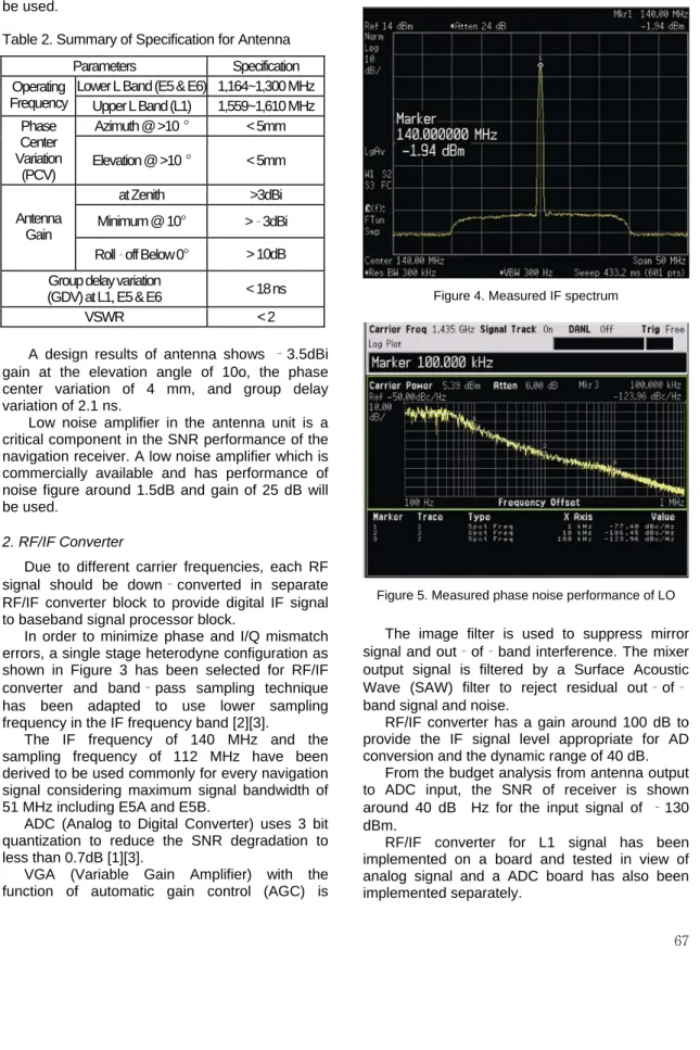
Figure 4. Measured IF spectrum
Figure 5. Measured phase noise performance of LO
![Figure 1. GALILEO/GPS spectrum [4]](https://thumb-ap.123doks.com/thumbv2/123dokinfo/5042543.554724/2.892.175.807.122.1097/figure-galileo-gps-spectrum.webp)