Copyright © The Institute of Positioning, Navigation, and Timing http://www.ipnt.or.kr Print ISSN: 2288-8187 Online ISSN: 2289-0866
1. INTRODUCTION
Recently, various Location Based Services (LBS) have emerged due to the price drop of the Global Navigation Satellite System (GNSS) receiver chips and the widespread of smartphones. LBS refers to all services that utilize the user's location information and is available in various fields such as commerce, navigation, and security. In particular, developed countries are building social safety networks based on location information, and the Federal Communications Commission (FCC) and the European Emergency Number Association of the European Union (EU) are establishing positioning performance requirements to ensure the accuracy of the location information of rescue requesters to be provided to emergency rescue agencies (FCC 2015, ECC 2016). In 2015, Korea also established standards for emergency rescue positioning systems to
A-GNSS Performance Test in Various Urban Environments by Using a Commercial Low Cost GNSS Receiver and Service
Kahee Han
1, Jung-Hoon Lee
1, Ji-Ung Im
2, Jong-Hoon Won
1†1
Department of Electrical Engineering, Inha University, Incheon 22212, Korea
2
Department of Future Vehicle Engineering, Inha University, Incheon 22212, Korea
ABSTRACT
The recent emergence of new Global Navigation Satellite Systems (GNSS) has resulted in a gradual improvement in the performance of positioning services. This paper verifies the degree of improvement in positioning performance of Assisted- GNSS (A-GNSS) receivers using assistance information compared to standalone-GNSS receivers that do not use assistance information in various urban environments in Korea. For this purpose, field tests are performed in various urban and indoor environments in Korea. The assistance information is provided by u-blox's AssistNow Online and low-cost commercial receivers are used for mobile station receivers. Through experiments, the Time to First Fix (TTFF), acquisition sensitivity, and position accuracy performance improvement are analyzed. The results of the experiments show that using assistance data improved the performance in all experiment locations, and, in particular, a significant performance improvement in terms of TTFF.
Keywords: navigation, positioning, A-GPS/A-GNSS, navigation performance
guarantee the interoperability of positioning systems that provide the location information of rescue requesters in case of crime, fire, and disaster, as well as to improve positioning performance (TTA 2015, 2016a,b, 2017a,b).
One of the typical emergency rescue services using location information is the EU emergency call (e-call). e-Call is an In-Vehicle System (IVS) that requests for rescue by automatically or manually sending the accident location and time information to an emergency rescue organization in the event of a serious car accident, which is required to be installed in all vehicles sold in Europe as of March 2018 (The European Parliament and the Council of the European Union 2015). Currently, the e-Call system in Europe is designed to send a Minimum Set of Data (MSD) from the e-Call IVS to the closest Public Safety Answering Point via a cellular network (e.g. GSM, UMTS). The MSD is standardized data that includes information such as the number of passengers, the accident time, and the location of the accident vehicle.
The Next Generation e-Call (NG e-Call), which is recently being discussed, plans to phase out the existing GSM and UMTS networks and replace them with 4G LTE and 5G infrastructure. Fig. 1 shows the principle of data transfer Received Sep 20, 2018 Revised Nov 06, 2018 Accepted Nov 13, 2018
†
Corresponding Author E-mail: [email protected]
Tel: +82-32-860-7406 Fax: +82-32-863-5822
in the traditional e-Call and NG e-Call systems (Rohde &
Schwarz 2018a,b).
The location information of the accident vehicle in the MSD is key data for a quick rescue. The e-Call IVS uses positioning technology using satellite navigation systems such as Global Positioning System (GPS) to generate location information of rescue requesters. The location information obtained through satellite navigation systems can be used globally and has the advantage of high positioning accuracy. In addition, multi-GNSS services are now available with the operation of new GNSS (or Regional Navigation Satellite System, RNSS) such as EU’s Galileo, China’s BeiDou navigation satellite system (BDS), Japan’s Quasi-Zenith Satellite System (QZSS), and as a result, the positioning performance has been significantly improved compared to standalone-GPS. On the other hand, GNSS- based positioning requires receivers to observe a certain level of Line of Sight (LOS) signals. Therefore, the positioning results of standalone-GNSS receivers in urban environments, where the LOS is not sufficiently secured, such as an area concentrated with high-rise buildings, can have low accuracy and in addition, it takes a long time to obtain positioning results.
However, Assisted-GNSS (A-GNSS) receivers which receive assistance information from the outside via wireless networks can compensate the disadvantages of standalone-GNSS receivers by using the assistance information provided for positioning (van Digglen 2009). The assistance information provided externally helps GNSS receivers to acquire signals and derive navigation solutions, and is roughly classified into acquisition assistance information, sensitivity assistance information, and navigation assistance information. Although various studies on the improved positioning performance of A-GNSS receivers have been reported in various academic
papers and reports (Karunanayake et al. 2007, Singh 2007, López et al. 2010), these results are based on considering the GNSS signal reception environments in foreign countries.
Recently, Korea is also proposing policies and implementing standardization to develop and commercialize ICT-based emergency rescue system technologies and aims to build a Korean e-Call system by June 2019 (Korea Transportation Safety Authority 2016). Therefore, in order to use A-GNSS receivers, tests on the positioning performance of A-GNSS receivers considering the multi-GNSS satellite arrangement status in the sky of Korea is required to verify the improvement of positioning performance in Korea.
This paper is structured as follows. Chapter 2 briefly introduces the concept and features of A-GNSS technique, and Chapter 3 analyzes the signal processing performance improvement according to the application of A-GNSS techniques. Chapter 4 describes the field tests performed in urban and indoor environments, and the test results are analyzed from the perspective of improving the performance of the Geometric Dilution of Precision (GDOP) according to the signal acquisition sensitivity and satellite arrangement as well as Time to First Fix (TTFF) according to the provision of assistance data. Lastly, Chapter 5 draws the conclusion.
2. ASSISTED-GNSS TECHNIQUE
The A-GNSS technique was developed due to the need
to reduce the time to obtain navigation solutions and to
increase the sensitivity of GNSS receivers. The weakness
of standalone-GNSS positioning is that it takes a long time
to obtain satellite orbital information and satellite clock
correction information included in received signals. For
example, when using GPS L1 C/A signals having a NAV
Fig. 1. Legacy e-Call (left) and NG e-Call (right) data transfer principle (Rohde & Schwarz 2018a,b).
http://www.ipnt.or.kr message structure, a minimum of 30 seconds is required to
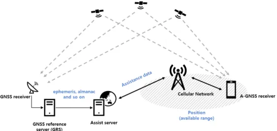
extract, through demodulation, orbit information and clock correction components required for positioning. In addition, if received signals are not strong enough, acquisition process may take a long time. Meanwhile, A-GNSS receivers can estimate the location of the receiver in a shorter time by receiving the time information, approximate user location, approximate Doppler frequency, and the ephemeris and almanac of visible satellite from assistant servers. The information obtained from GNSS signals, such as visible satellite list, ephemeris, almanac, and satellite health status is provided to the server by permanently operating GNSS reference stations. In case of providing time information to the assistant server from a separate source that provides accurate time, A-GNSS receivers can also receive precise time assistance information and can correct the local oscillator of A-GNSS receivers using the reference frequency provided from the cell tower of the mobile communication network.
Fig. 2 roughly shows the flow of assistance information in the A-GNSS technique.
The assistance information can be largely classified into acquisition, sensitivity, and navigation assistance information depending on the purpose. The acquisition assistance information is provided to reduce the TTFF at the receiver and typically includes a list of visible satellites, Doppler/code delay estimates, and ephemeris information.
The sensitivity assistance information is provided so that the receiver has a low acquisition threshold, and typically includes information about navigation data bits. The navigation assistance information is provided to improve the accuracy and integrity of the navigation solution generated by the receiver, and includes differential GNSS (DGNSS) correction data, approximate receiver location, and real- time satellite integrity information. Table 1 shows a detailed list of assistance information that corresponds to the above- mentioned 3 categories.
Meanwhile, the A-GNSS technique can be divided into MS-Assisted (MSA) and MS-Based (MSB) depending on whether the element that finally calculates location is from the assistance information from an external server or a Fig. 2. Overview of generating and transmitting assistance data in the network.
Table 1. Classification of assistance data according to purpose (Kaplan & Hegarty 2006).
Forms Purpose Assistance data
Acquisition assistance to reduce the GPS receiver’s time to generate a fix-time to first fix (TTFF)
A list of visible satellites, Predicted GPS satellite Dopplers and Doppler rates, Azimuth and elevation angles for the visible satellites, Local oscillator offset information, Approximate mobile location, GPS satellite ephemeris information, GPS almanac, Satellite clock correction terms, Approximate GPS time, Precise GPS time, Predicted code phases, Predicted code phase search window, Navigation data bit timing information (bit number, fractional bit), Navigation data bits Sensitivity assistance to help the GPS receiver lower
its acquisition thresholds
Navigation data bit timing information (bit number, fractional bit), Navigation data bits
Navigation assistance to improve the accuracy or integrity of the position solution generated by the GPS receiver
DGPS correction data, Approximate altitude of the mobile, Approximate mobile
location, Real-time satellite integrity information, Fine GPS timing information,
Satellite clock correction coefficients, GPS satellite ephemeris information
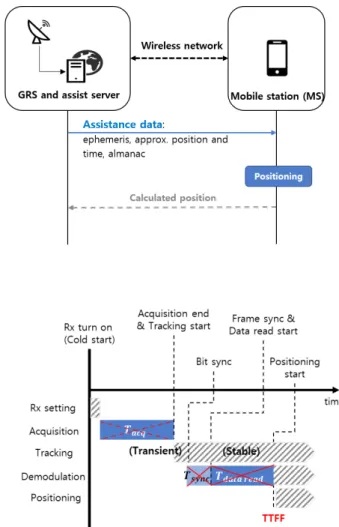
Mobile Station (MS). Fig. 3 shows the flow of assistance data according to MSA or MSB method. First, in the case of MSA, which calculates the user’s location at the server, there is an advantage of sending only a small amount of assistance data from the server to the MS. At this time, the assistance data provided by the server is the list of visible satellites, Doppler, and code phase information corresponding to the acquisition assistance information. These assistance data allows the receiver to rapidly acquire signals by reducing the number of search satellites and the search area. The Doppler, code phase, and C/N0 information obtained are transmitted back to the server, and the server calculates the location of the receiver based on such information. On the other hand, the MSB method calculates the location at the MS based on the assistance information provided by the server. The assistance information provided to the MS from the server to use the MSB technique includes ephemeris, approximate location and time, and almanac. The A-GNSS receiver can use the assistance information to calculate its location before completing tasks such as acquisition and synchronization.
When using the MSA method, some of the functions of conventional GNSS receivers are performed at the assistant server, thereby reducing the processing power consumption required for signal processing at the MS. In addition, when multiple rescue agencies want to acquire location information from the MS for emergency rescue activities, it is more efficient to provide the MS location information to each rescue agency from the assistant server than each agency requesting the information. Meanwhile, when the MS is moving, ongoing communication between the MS and the server is necessary for accurate positioning. Therefore, if a sufficient data rate is not secured, it is not suitable for continually estimating the location of the moving MS. On the other hand, when using the MSB method, the assistance information provided by the server is not greatly affected
by the movement of the user. Therefore, it is possible to operate as a normal A-GNSS receiver without additional communication with the server for a certain period of time in which the assistance information provided is valid (about 2 hours in case of ephemeris), making the MSB method suitable for cases that demand rapid location estimation such as navigation in vehicles. However, the disadvantage is that a relatively large amount of data needs to be provided from the server at the initial stage of operation. It also requires higher hardware specifications and processing power as the MS calculates the location.
3. EFFECTS OF ASSISTED DATA ON GNSS PERFORMANCE
3.1 Time to First Fix
TTFF is the time required for GNSS receivers to acquire satellite signals and navigation data, and then to calculate Fig. 3. MS-assisted (left) and MS-based (right) positioning methods.
Fig. 4. TTFF in A-GNSS receiver.
http://www.ipnt.or.kr positioning results. GNSS receivers perform several signal
processing procedures until obtaining the first positioning result after power is supplied. This is shown in Fig. 4, and the detailed formula is as follows (Won et al. 2008).
TTFF is the time required for GNSS receivers to acquire satellite signals and navigation data, and then to calculate positioning results. GNSS receivers perform several signal processing procedures until obtaining the first positioning result after power is supplied. This is shown in Fig. 4, and the detailed formula is as follows (Won et al. 2008).
TTFF = T
RX setting+ ∑
4𝑇𝑇
𝑎𝑎𝑎𝑎𝑎𝑎𝑎𝑎𝑎𝑎=1
+ 𝑇𝑇
𝑏𝑏𝑎𝑎𝑏𝑏 𝑠𝑠𝑠𝑠𝑠𝑠𝑎𝑎+ 𝑇𝑇
𝑓𝑓𝑓𝑓𝑎𝑎𝑓𝑓𝑓𝑓 𝑠𝑠𝑠𝑠𝑠𝑠𝑎𝑎+ 𝑇𝑇
𝑑𝑑𝑎𝑎𝑏𝑏𝑎𝑎 𝑓𝑓𝑓𝑓𝑎𝑎𝑑𝑑(1) where 𝑇𝑇
𝑅𝑅𝑅𝑅 𝑠𝑠𝑓𝑓𝑏𝑏𝑏𝑏𝑎𝑎𝑠𝑠𝑠𝑠is the receiver warm-up time for proper operation, 𝑇𝑇
𝑎𝑎𝑎𝑎𝑎𝑎𝑎𝑎is the acquisition time for the
ith satellite signal, 𝑇𝑇𝑏𝑏𝑎𝑎𝑏𝑏 𝑠𝑠𝑠𝑠𝑠𝑠𝑎𝑎is the bit synchronization time for navigation data demodulation, 𝑇𝑇
𝑓𝑓𝑓𝑓𝑎𝑎𝑓𝑓𝑓𝑓 𝑠𝑠𝑠𝑠𝑠𝑠𝑎𝑎is the starting point search time of the navigation message frame (or page) for valid data bit demodulation, and 𝑇𝑇
𝑑𝑑𝑎𝑎𝑏𝑏𝑎𝑎 𝑓𝑓𝑓𝑓𝑎𝑎𝑑𝑑is the navigation message demodulation time.
TTFF can be categorized as cold start, warm start, and hot start depending on the level of initial information of a GNSS receiver (US Coast Guard 1996). In particular for cold start corresponding to the factory-default state, the acquisition time can be reduced by using the list of visible satellites, Doppler, and code phase provided by the server. In addition, the TTFF can be further significantly reduced, since synchronization and demodulation are not required to extract information such as ephemeris from navigation data.
3.2 Acquisition Sensitivity
The signal acquisition sensitivity is defined as the minimum signal power required to acquire a certain reliability (i.e., detection probability and false detection probability) (Weil 2011). When using acquisition assistance information, it is possible to reduce the Doppler and code delay uncertainty, thereby reducing the search area in the acquisition stage. Therefore, signal detection sensitivity can be increased within a given time in signal processing, by allocating a long dwell time around search cells that are expected to have a signal or by reducing the size of the search cell by further subdividing the reduced search area.
Meanwhile, the use of sensitivity assistance information, that is, the navigation data bit and timing information, enables an increase in the Predetection Integration Time (PIT) in a weak signal environment such as indoor location. A priori knowledge of full navigation data message then enables data wipe-off if necessary for an additional signal processing gain. Therefore, if the navigation data bits provided as assistance information can be synchronized to the data bit edges of the satellite signals for signals intended to be acquired, then the PIT can be extended beyond a single navigation data bit duration (20 ms for GPS L1 CA), which results in improvements in signal sensitivity.
3.3 Positioning Accuracy
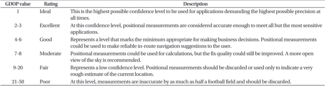
The GNSS positioning accuracy is determined by the User Equivalent Ranging Error (UERE) and GDOP, and is expressed through statistical distribution. The UERE is an index that shows the distance measurement error for each satellite from the perspective of the receiver. The UERE varies according to the satellite signal, signal propagation characteristics, and the random changes in the user measurement process, and also varies over time for each satellite. The GDOP is a non-dimensional index representing the error caused by the satellite’s geometric relationship from the perspective of the receiver. For a given value, a small GDOP value means more accurate location and time. Since the relative geometrical relationship between satellites changes over time, the GDOP also changes over time. As a result, the GDOP can vary according to time and user location, and is used to estimate real-time accuracy since it can be easily measured by the receiver (U.S. Coast Guard 1996). According to Person (2008), GDOP values can be interpreted as shown in Table 2.
Eq. (2) shows that the GPS positioning accuracy is due to the relative geometrical arrangement of satellites used for positioning and the pseudo-range measurement error.
TTFF is the time required for GNSS receivers to acquire satellite signals and navigation data, and then to calculate positioning results. GNSS receivers perform several signal processing procedures until obtaining the first positioning result after power is supplied. This is shown in Fig. 4, and the detailed formula is as follows (Won et al. 2008).
TTFF = T
RX setting+ ∑
4𝑇𝑇
𝑎𝑎𝑎𝑎𝑎𝑎𝑎𝑎𝑎𝑎=1
+ 𝑇𝑇
𝑏𝑏𝑎𝑎𝑏𝑏 𝑠𝑠𝑠𝑠𝑠𝑠𝑎𝑎+ 𝑇𝑇
𝑓𝑓𝑓𝑓𝑎𝑎𝑓𝑓𝑓𝑓 𝑠𝑠𝑠𝑠𝑠𝑠𝑎𝑎+ 𝑇𝑇
𝑑𝑑𝑎𝑎𝑏𝑏𝑎𝑎 𝑓𝑓𝑓𝑓𝑎𝑎𝑑𝑑(1) where 𝑇𝑇
𝑅𝑅𝑅𝑅 𝑠𝑠𝑓𝑓𝑏𝑏𝑏𝑏𝑎𝑎𝑠𝑠𝑠𝑠is the receiver warm-up time for proper operation, 𝑇𝑇
𝑎𝑎𝑎𝑎𝑎𝑎𝑎𝑎is the acquisition time for the
ith satellite signal, 𝑇𝑇𝑏𝑏𝑎𝑎𝑏𝑏 𝑠𝑠𝑠𝑠𝑠𝑠𝑎𝑎is the bit synchronization time for navigation data demodulation, 𝑇𝑇
𝑓𝑓𝑓𝑓𝑎𝑎𝑓𝑓𝑓𝑓 𝑠𝑠𝑠𝑠𝑠𝑠𝑎𝑎is the starting point search time of the navigation message frame (or page) for valid data bit demodulation, and 𝑇𝑇
𝑑𝑑𝑎𝑎𝑏𝑏𝑎𝑎 𝑓𝑓𝑓𝑓𝑎𝑎𝑑𝑑is the navigation message demodulation time.
TTFF can be categorized as cold start, warm start, and hot start depending on the level of initial information of a GNSS receiver (US Coast Guard 1996). In particular for cold start corresponding to the factory-default state, the acquisition time can be reduced by using the list of visible satellites, Doppler, and code phase provided by the server. In addition, the TTFF can be further significantly reduced, since synchronization and demodulation are not required to extract information such as ephemeris from navigation data.
3.2 Acquisition Sensitivity
The signal acquisition sensitivity is defined as the minimum signal power required to acquire a certain reliability (i.e., detection probability and false detection probability) (Weil 2011). When using acquisition assistance information, it is possible to reduce the Doppler and code delay uncertainty, thereby reducing the search area in the acquisition stage. Therefore, signal detection sensitivity can be increased within a given time in signal processing, by allocating a long dwell time around search cells that are expected to have a signal or by reducing the size of the search cell by further subdividing the reduced search area.
Meanwhile, the use of sensitivity assistance information, that is, the navigation data bit and timing information, enables an increase in the Predetection Integration Time (PIT) in a weak signal environment such as indoor location. A priori knowledge of full navigation data message then enables data wipe-off if necessary for an additional signal processing gain. Therefore, if the navigation data bits provided as assistance information can be synchronized to the data bit edges of the satellite signals for signals intended to be acquired, then the PIT can be extended beyond a single navigation data bit duration (20 ms for GPS L1 CA), which results in improvements in signal sensitivity.
3.3 Positioning Accuracy
The GNSS positioning accuracy is determined by the User Equivalent Ranging Error (UERE) and GDOP, and is expressed through statistical distribution. The UERE is an index that shows the distance measurement error for each satellite from the perspective of the receiver. The UERE varies according to the satellite signal, signal propagation characteristics, and the random changes in the user measurement process, and also varies over time for each satellite. The GDOP is a non-dimensional index representing the error caused by the satellite’s geometric relationship from the perspective of the receiver. For a given value, a small GDOP value means more accurate location and time. Since the relative geometrical relationship between satellites changes over time, the GDOP also changes over time. As a result, the GDOP can vary according to time and user location, and is used to estimate real-time accuracy since it can be easily measured by the receiver (U.S. Coast Guard 1996). According to Person (2008), GDOP values can be interpreted as shown in Table 2.
Eq. (2) shows that the GPS positioning accuracy is due to the relative geometrical arrangement of satellites used for positioning and the pseudo-range measurement error.
(1)
where T
RX settingis the receiver warm-up time for proper operation, T
acqiis the acquisition time for the i
thsatellite signal, T
bit syncis the bit synchronization time for navigation data demodulation, T
frame syncis the starting point search time of the navigation message frame (or page) for valid data bit demodulation, and T
data readis the navigation message demodulation time.
TTFF can be categorized as cold start, warm start, and hot start depending on the level of initial information of a GNSS receiver (US Coast Guard 1996). In particular for cold start corresponding to the factory-default state, the acquisition time can be reduced by using the list of visible satellites, Doppler, and code phase provided by the server.
In addition, the TTFF can be further significantly reduced, since synchronization and demodulation are not required to extract information such as ephemeris from navigation data.
3.2 Acquisition Sensitivity
The signal acquisition sensitivity is defined as the minimum signal power required to acquire a certain reliability (i.e., detection probability and false detection probability) (Weil 2011). When using acquisition assistance information, it is possible to reduce the Doppler and code delay uncertainty, thereby reducing the search area in the acquisition stage. Therefore, signal detection sensitivity can be increased within a given time in signal processing, by allocating a long dwell time around search cells that are expected to have a signal or by reducing the size of the search cell by further subdividing the reduced search area.
Meanwhile, the use of sensitivity assistance information,
that is, the navigation data bit and timing information, enables an increase in the Predetection Integration Time (PIT) in a weak signal environment such as indoor location.
A priori knowledge of full navigation data message then enables data wipe-off if necessary for an additional signal processing gain. Therefore, if the navigation data bits provided as assistance information can be synchronized to the data bit edges of the satellite signals for signals intended to be acquired, then the PIT can be extended beyond a single navigation data bit duration (20 ms for GPS L1 CA), which results in improvements in signal sensitivity.
3.3 Positioning Accuracy
The GNSS positioning accuracy is determined by the User Equivalent Ranging Error (UERE) and GDOP, and is expressed through statistical distribution. The UERE is an index that shows the distance measurement error for each satellite from the perspective of the receiver. The UERE varies according to the satellite signal, signal propagation characteristics, and the random changes in the user measurement process, and also varies over time for each satellite. The GDOP is a non-dimensional index representing the error caused by the satellite’s geometric relationship from the perspective of the receiver. For a given value, a small GDOP value means more accurate location and time.
Since the relative geometrical relationship between satellites changes over time, the GDOP also changes over time. As a result, the GDOP can vary according to time and user location, and is used to estimate real-time accuracy since it can be easily measured by the receiver (U.S. Coast Guard 1996). According to Person (2008), GDOP values can be interpreted as shown in Table 2.
Eq. (2) shows that the GPS positioning accuracy is due to the relative geometrical arrangement of satellites used for positioning and the pseudo-range measurement error.
error in Positioning Solution = GDOP ∗ UERE (2) For GPS, the system requirement accuracy has been defined by the Department of Defense and the North Atlantic Treaty Organization (US Coast Guard 1996). When using navigation assistance information, a lower UERE value for the corresponding satellite can be obtained by lowering the level of satellite ephemeris errors and satellite clock errors. In addition, more satellites can be obtained as a result of good acquisition sensitivity, and a lower GDOP value can be obtained by using precise time assistance data.
4. FIELD TEST 4.1 Test Environment
The field test was performed using EVK-M8T receivers from u-blox as shown in Fig. 5a and the data from the free AssistNow A-GNSS service by u-blox was used as assistance information. AssistNow data is collected by u-blox's global satellite receivers and is maintained in real-time on u-blox AssistNow servers accessible via the Internet. Fig. 6 shows the GUI used to request assistance information from the AssistNow server. The information that the user can randomly enter into this GUI includes reference location, systems that will receive the assistance information (e.g. GPS, BeiDou, etc.), the type of assistance information to be provided, and the type of time assistance information. A detailed description of each input value is also provided by the manufacturer (Ublox 2015). Meanwhile, the EVK-M8T receiver cannot use GLONASS and BeiDou simultaneously due to its characteristics (Ublox 2015).
Therefore, GPS, Galileo, BeiDou and QZSS are used in the experiment in this study, and hereinafter GNSS refers to these systems.
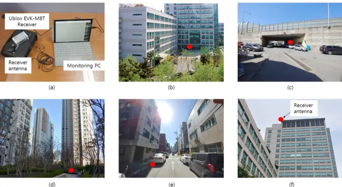
The experimental sites were selected as shown in Fig. 5 and Table 3, in order to compare the performance of standalone-GNSS receiver and A-GNSS receiver in various reception environments in urban areas. As shown in Fig. 5, the building lobby and underpass are harsh environments to obtain the LOS between reception antenna and visible satellites. The LOS between satellites can be secured through one side of the glass in the lobby. But in the underpass, it is difficult to secure the LOS between antenna and visible satellites. In apartment complexes or residential areas, the LOS for high elevation satellites can be obtained, but it is difficult obtain the LOS for low elevation satellites. It is possible to obtain more LOS for low elevation satellites in apartment complexes compared to residential areas due to the wide space between buildings. The Rooftop was selected as the highest place around, where it is possible to secure the LOS with all visible satellites at all times. In order to compare performance improvements over standalone-GNSS receivers when using only using assistance data on GPS (i.e. A-GPS) and using assistance data on all GNSS (i.e. A-GNSS), this study performed additional tests using A-GPS receivers in the lobby and open sky (rooftop) environment.
4.2 Test Results
The experiments were performed 10 times for each scenario and the TTFF was analyzed by averaging the TTFF values for each scenario. The signal acquisition sensitivity was analyzed using the average values for each scenario, after selecting the minimum 𝐶𝐶/𝑁𝑁
0among the satellite signals used at each TTFF point. The positioning accuracy, as shown in Eq. (2), is closely related to the GDOP.
Therefore, this paper replaces positioning accuracy with the GDOP. The GDOP was analyzed by averaging the values from the TTFF point to the time outputting positioning results 30 times. The reason why the analysis of location accuracy was omitted in this paper is that it was difficult to accurately analyze location errors because of the absence of the precise reference position for indoor positioning.
Therefore, the analysis was replaced by determining whether it is possible to estimate the approximate (2)
Table 2. Jon's interpretation of dilution of precision values (Person 2008).
GDOP value Rating Description
1 Ideal This is the highest possible confidence level to be used for applications demanding the highest possible precision at all times.
2-3 Excellent At this confidence level, positional measurements are considered accurate enough to meet all but the most sensitive applications.
4-6 Good Represents a level that marks the minimum appropriate for making business decisions. Positional measurements could be used to make reliable in-route navigation suggestions to the user.
7-8 Moderate Positional measurements could be used for calculations, but the fix quality could still be improved. A more open view of the sky is recommended.
9-20 Fair Represents a low confidence level. Positional measurements should be discarded or used only to indicate a very rough estimate of the current location.
21-50 Poor At this level, measurements are inaccurate by as much as half a football field and should be discarded.
For GPS, the system requirement accuracy has been defined by the Department of Defense and the North Atlantic Treaty Organization (US Coast Guard 1996). When using navigation assistance information, a lower UERE value for the corresponding satellite can be obtained by lowering the level of satellite ephemeris errors and satellite clock errors.
In addition, more satellites can be obtained as a result of good acquisition sensitivity, and a lower GDOP value can be obtained by using precise time assistance data.
4. FIELD TEST
4.1 Test Environment
The field test was performed using EVK-M8T receivers from u-blox as shown in Fig. 5a and the data from the free AssistNow A-GNSS service by u-blox was used as assistance information. AssistNow data is collected by u-blox's global satellite receivers and is maintained in real-time on u-blox AssistNow servers accessible via the Internet. Fig. 6 shows the GUI used to request assistance information from the AssistNow server. The information that the user can randomly enter into this GUI includes reference location, systems that will receive the assistance information (e.g.
GPS, BeiDou, etc.), the type of assistance information to be
provided, and the type of time assistance information. A detailed description of each input value is also provided by the manufacturer (Ublox 2015). Meanwhile, the EVK-M8T receiver cannot use GLONASS and BeiDou simultaneously due to its characteristics (Ublox 2015). Therefore, GPS, Galileo, BeiDou and QZSS are used in the experiment in this study, and hereinafter GNSS refers to these systems.
The experimental sites were selected as shown in Fig. 5 and Table 3, in order to compare the performance of standalone- GNSS receiver and A-GNSS receiver in various reception environments in urban areas. As shown in Fig. 5, the building Fig. 5. Test scenarios and equipment: (a) test equipment, (b) lobby, (c) underpass, (d) apartment complex, (e) residential area, (f) rooftop (open-sky).
Table 3. Test locations.
Test locations Describes
Lobby (Fig. 5b) On the 1st floor of the 16-story building
One side is made of glass and the other three sides are clogged with a wall
Underpass (Fig. 5c) A narrow passage under the overpass
The three sides are clogged with thick concrete walls Apartment complex
(Fig. 5d) High-rise apartment complex
Surrounded by apartments on all sides, and there are many trees around
Distance between buildings is wide Residential area
(Fig. 5e) Low-rise residential area where flats are concentrated
Distance between flats is short Rooftop (Fig. 5f) Rooftop of 15-story building
There is no high-rise building in the surroundings
and the view is open
http://www.ipnt.or.kr lobby and underpass are harsh environments to obtain the
LOS between reception antenna and visible satellites. The LOS between satellites can be secured through one side of the glass in the lobby. But in the underpass, it is difficult to secure the LOS between antenna and visible satellites. In apartment complexes or residential areas, the LOS for high elevation satellites can be obtained, but it is difficult obtain the LOS for low elevation satellites. It is possible to obtain more LOS for low elevation satellites in apartment complexes compared to residential areas due to the wide space between buildings.
The Rooftop was selected as the highest place around, where it is possible to secure the LOS with all visible satellites at all times. In order to compare performance improvements over standalone-GNSS receivers when using only using assistance data on GPS (i.e. A-GPS) and using assistance data on all GNSS (i.e. A-GNSS), this study performed additional tests using A-GPS receivers in the lobby and open sky (rooftop) environment.
4.2 Test Results
The experiments were performed 10 times for each scenario and the TTFF was analyzed by averaging the TTFF values for each scenario. The signal acquisition sensitivity was analyzed using the average values for each scenario, after selecting the minimum C/N
0among the satellite signals used at each TTFF point. The positioning accuracy, as shown in
Eq. (2), is closely related to the GDOP. Therefore, this paper replaces positioning accuracy with the GDOP. The GDOP was analyzed by averaging the values from the TTFF point to the time outputting positioning results 30 times. The reason why the analysis of location accuracy was omitted in this paper is that it was difficult to accurately analyze location errors because of the absence of the precise reference position for indoor positioning. Therefore, the analysis was replaced by determining whether it is possible to estimate the approximate location on the map.
4.2.1 Time to first fix
The comparison of TTFF according to the use of a standalone-GNSS receiver, A-GPS receiver or A-GNSS receiver in each experimental site is shown in Fig. 7.
Considering that the low-cost commercial GNSS chipset is the multiple GNSS, this study only tested the Assisted- GNSS in underpass, apartment, and residential area. In the case of poor reception environments such as lobby and underpass, the difference was more than 1 minute depending on the use of assistance information. On the other hand, in the apartment complex, residential area, and rooftop where the reception environment is relatively good, the difference in TTFF was observed to be the amount of time required to extract the ephemeris. Table 4 summarizes the TTFF obtained for each experimental site and for each receiver used. This study confirmed that the performance Fig. 6. The GUI of AssistNow online.
Fig. 7. Comparison of TTFF [sec] for each scenario; Standalone-GNSS vs.
A-GPS vs. A-GNSS.
Table 4. TTFF [sec] for each scenario.
Receiver Location
TTFF [sec] Difference of TTFF between cold start and A-GNSS [sec]
Standalone-
GNSS A-GPS A-GNSS
Lobby 90.209 9.807 9.217 -61.305
Underpass 329.716 - 16.192 -313.524
Apartment complex 28.646 - 2.432 -26.214
Residential area 30.377 - 3.065 -27.312
Rooftop 27.664 2.524 2.214 -25.45
was improved in terms of TTFF when using assistance information for all experimental sites. In particular, in the underpasses and lobby where the reception is very poor, the TTFF gains were 313 seconds and 61 seconds, respectively, when using assistance information, which meet the 30-second requirement by the FCC (2015). Meanwhile, the reason why the TTFF gain varies depending on experimental site is that signals with low C/N
0take a relatively longer amount of time to acquire ephemeris and signals compared to signals with high C/N
0. In conclusion, as shown in Fig. 7 and Table 4, although the provision of assistance information leads to a large TTFF performance difference, whether the assistance information provided was from a large number of GNSS (i.e., whether it is an A-GPS receiver or an A-GNSS receiver) did not have a significant impact.
4.2.2 Acquisition sensitivity
In order to effectively analyze the influence of the use of assistance information received from the server on acquisition sensitivity, the analysis in this study was focused on the lobby and underpass, which are expected to have
relatively low reception C/N
0among the 5 experimental sites.
According to the data sheet provided by u-blox, the EVK- M8T receiver has different acquisition sensitivities depending on the system used for positioning and the use of assistance data. The sensitivity values according to each case are summarized in Table 5 (Ublox 2015). The minimum C/N
0that can be received based on the sensitivity values in Table 5 can be calculated as shown in Eq. (3).
location on the map.
4.2.1 Time to first fix
The comparison of TTFF according to the use of a standalone-GNSS receiver, A-GPS receiver or A- GNSS receiver in each experimental site is shown in Fig. 7. Considering that the low-cost commercial GNSS chipset is the multiple GNSS, this study only tested the Assisted-GNSS in underpass, apartment, and residential area. In the case of poor reception environments such as lobby and underpass, the difference was more than 1 minute depending on the use of assistance information. On the other hand, in the apartment complex, residential area, and rooftop where the reception environment is relatively good, the difference in TTFF was observed to be the amount of time required to extract the ephemeris. Table 4 summarizes the TTFF obtained for each experimental site and for each receiver used. This study confirmed that the performance was improved in terms of TTFF when using assistance information for all experimental sites. In particular, in the underpasses and lobby where the reception is very poor, the TTFF gains were 313 seconds and 61 seconds, respectively, when using assistance information, which meet the 30-second requirement by the FCC (2015). Meanwhile, the reason why the TTFF gain varies depending on experimental site is that signals with low C/N
0take a relatively longer amount of time to acquire ephemeris and signals compared to signals with high C/N
0. In conclusion, as shown in Fig. 7 and Table 4, although the provision of assistance information leads to a large TTFF performance difference, whether the assistance information provided was from a large number of GNSS (i.e., whether it is an A-GPS receiver or an A-GNSS receiver) did not have a significant impact.
4.2.2 Acquisition sensitivity
In order to effectively analyze the influence of the use of assistance information received from the server on acquisition sensitivity, the analysis in this study was focused on the lobby and underpass, which are expected to have relatively low reception 𝐶𝐶/𝑁𝑁
0among the 5 experimental sites.
According to the data sheet provided by u-blox, the EVK-M8T receiver has different acquisition sensitivities depending on the system used for positioning and the use of assistance data. The sensitivity values according to each case are summarized in Table 5 (Ublox 2015). The minimum 𝐶𝐶/𝑁𝑁
0that can be received based on the sensitivity values in Table 5 can be calculated as shown in Eq. (3).
𝐶𝐶/𝑁𝑁
0= (𝑠𝑠𝑠𝑠𝑠𝑠𝑠𝑠𝑠𝑠𝑠𝑠𝑠𝑠𝑠𝑠𝑠𝑠𝑠𝑠𝑠𝑠 𝑝𝑝𝑝𝑝𝑝𝑝𝑠𝑠𝑝𝑝) + (𝑠𝑠ℎ𝑠𝑠𝑝𝑝𝑒𝑒𝑒𝑒𝑒𝑒 𝑠𝑠𝑝𝑝𝑠𝑠𝑠𝑠𝑠𝑠 𝑑𝑑𝑠𝑠𝑠𝑠𝑠𝑠𝑠𝑠𝑠𝑠𝑠𝑠) − (𝑁𝑁𝑝𝑝𝑠𝑠𝑠𝑠𝑠𝑠 𝐹𝐹𝑠𝑠𝐹𝐹𝐹𝐹𝑝𝑝𝑠𝑠) (3) The thermal noise power density of the M8T receiver is typically 174dBm and the noise figure is 3~6 dB. The minimum receivable 𝐶𝐶/𝑁𝑁
0according to each case, calculated based on Table 5 and Eq. (3), is as shown in Table 6. Using assistance information through Table 6 results in a 𝐶𝐶/𝑁𝑁
0gain of at least 3 dB-Hz and up to 11 dB-Hz.
Fig. 8 shows the minimum 𝐶𝐶/𝑁𝑁
0in the lobby and underpass. When using a standalone-GNSS receiver in the lobby, the average minimum 𝐶𝐶/𝑁𝑁
0of satellites used at the TTFF point is 32 dB-Hz, and with an A-GNSS receiver using assistance information, the average minimum 𝐶𝐶/𝑁𝑁
0is 20 dB-Hz, which results in a 𝐶𝐶/𝑁𝑁
0gain of about 12 dB-Hz. When using a standalone-GNSS receiver in the underpass, the average minimum 𝐶𝐶/𝑁𝑁
0of satellites used at the TTFF point is 27 dB-Hz, and the average minimum 𝐶𝐶/𝑁𝑁
0when using an A-GNSS receiver is 17 dB-Hz, which results in a 𝐶𝐶/𝑁𝑁
0gain of about 10 dB-Hz.
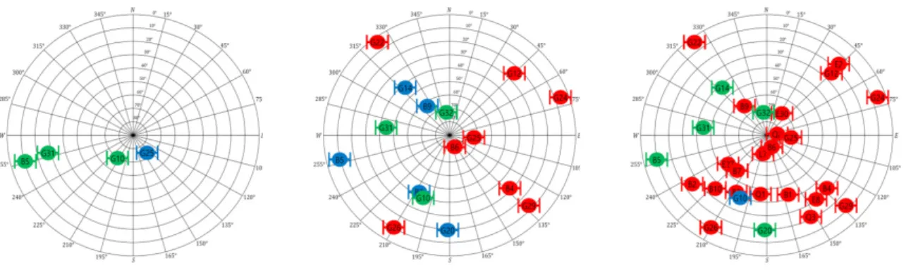
4.2.3 GDOP
Fig. 9 and Table 7 show the GDOPs according to the use of a standalone-GNSS receiver, A-GPS receiver or A-GNSS receiver for all experimental sites. Through evaluating the GDOP value in the lobby based on Table 2, it was found that the positioning results of the standalone-GNSS receiver could only be location on the map.
4.2.1 Time to first fix
The comparison of TTFF according to the use of a standalone-GNSS receiver, A-GPS receiver or A- GNSS receiver in each experimental site is shown in Fig. 7. Considering that the low-cost commercial GNSS chipset is the multiple GNSS, this study only tested the Assisted-GNSS in underpass, apartment, and residential area. In the case of poor reception environments such as lobby and underpass, the difference was more than 1 minute depending on the use of assistance information. On the other hand, in the apartment complex, residential area, and rooftop where the reception environment is relatively good, the difference in TTFF was observed to be the amount of time required to extract the ephemeris. Table 4 summarizes the TTFF obtained for each experimental site and for each receiver used. This study confirmed that the performance was improved in terms of TTFF when using assistance information for all experimental sites. In particular, in the underpasses and lobby where the reception is very poor, the TTFF gains were 313 seconds and 61 seconds, respectively, when using assistance information, which meet the 30-second requirement by the FCC (2015). Meanwhile, the reason why the TTFF gain varies depending on experimental site is that signals with low C/N
0take a relatively longer amount of time to acquire ephemeris and signals compared to signals with high C/N
0. In conclusion, as shown in Fig. 7 and Table 4, although the provision of assistance information leads to a large TTFF performance difference, whether the assistance information provided was from a large number of GNSS (i.e., whether it is an A-GPS receiver or an A-GNSS receiver) did not have a significant impact.
4.2.2 Acquisition sensitivity
In order to effectively analyze the influence of the use of assistance information received from the server on acquisition sensitivity, the analysis in this study was focused on the lobby and underpass, which are expected to have relatively low reception 𝐶𝐶/𝑁𝑁
0among the 5 experimental sites.
According to the data sheet provided by u-blox, the EVK-M8T receiver has different acquisition sensitivities depending on the system used for positioning and the use of assistance data. The sensitivity values according to each case are summarized in Table 5 (Ublox 2015). The minimum 𝐶𝐶/𝑁𝑁
0that can be received based on the sensitivity values in Table 5 can be calculated as shown in Eq. (3).
𝐶𝐶/𝑁𝑁
0= (𝑠𝑠𝑠𝑠𝑠𝑠𝑠𝑠𝑠𝑠𝑠𝑠𝑠𝑠𝑠𝑠𝑠𝑠𝑠𝑠𝑠𝑠 𝑝𝑝𝑝𝑝𝑝𝑝𝑠𝑠𝑝𝑝) + (𝑠𝑠ℎ𝑠𝑠𝑝𝑝𝑒𝑒𝑒𝑒𝑒𝑒 𝑠𝑠𝑝𝑝𝑠𝑠𝑠𝑠𝑠𝑠 𝑑𝑑𝑠𝑠𝑠𝑠𝑠𝑠𝑠𝑠𝑠𝑠𝑠𝑠) − (𝑁𝑁𝑝𝑝𝑠𝑠𝑠𝑠𝑠𝑠 𝐹𝐹𝑠𝑠𝐹𝐹𝐹𝐹𝑝𝑝𝑠𝑠) (3) The thermal noise power density of the M8T receiver is typically 174dBm and the noise figure is 3~6 dB. The minimum receivable 𝐶𝐶/𝑁𝑁
0according to each case, calculated based on Table 5 and Eq. (3), is as shown in Table 6. Using assistance information through Table 6 results in a 𝐶𝐶/𝑁𝑁
0gain of at least 3 dB-Hz and up to 11 dB-Hz.
Fig. 8 shows the minimum 𝐶𝐶/𝑁𝑁
0in the lobby and underpass. When using a standalone-GNSS receiver in the lobby, the average minimum 𝐶𝐶/𝑁𝑁
0of satellites used at the TTFF point is 32 dB-Hz, and with an A-GNSS receiver using assistance information, the average minimum 𝐶𝐶/𝑁𝑁
0is 20 dB-Hz, which results in a 𝐶𝐶/𝑁𝑁
0gain of about 12 dB-Hz. When using a standalone-GNSS receiver in the underpass, the average minimum 𝐶𝐶/𝑁𝑁
0of satellites used at the TTFF point is 27 dB-Hz, and the average minimum 𝐶𝐶/𝑁𝑁
0when using an A-GNSS receiver is 17 dB-Hz, which results in a 𝐶𝐶/𝑁𝑁
0gain of about 10 dB-Hz.
4.2.3 GDOP
Fig. 9 and Table 7 show the GDOPs according to the use of a standalone-GNSS receiver, A-GPS receiver or A-GNSS receiver for all experimental sites. Through evaluating the GDOP value in the lobby based on Table 2, it was found that the positioning results of the standalone-GNSS receiver could only be
(3)
The thermal noise power density of the M8T receiver is typically 174dBm and the noise figure is 3~6 dB. The minimum receivable C/N
0according to each case, calculated based on Table 5 and Eq. (3), is as shown in Table 6. Using assistance information through Table 6 results in a C/N
0gain of at least 3 dB-Hz and up to 11 dB-Hz.
Fig. 8 shows the minimum C/N
0in the lobby and underpass. When using a standalone-GNSS receiver in the lobby, the average minimum C/N
0of satellites used at the TTFF point is 32 dB-Hz, and with an A-GNSS receiver using assistance information, the average minimum C/N
0is 20 dB- Hz, which results in a C/N
0gain of about 12 dB-Hz. When Fig. 8. Comparison of minimum value of used signals C/N0 [dB-Hz];
Standalone-GNSS vs. A-GNSS.
Table 7. GDOP for each scenario.
Receiver Location
GDOP Difference of GDOP
between standalone- GNSS and A-GNSS Standalone-
GNSS A-GPS A-GNSS
![Table 4. TTFF [sec] for each scenario.](https://thumb-ap.123doks.com/thumbv2/123dokinfo/5262974.632064/7.892.86.431.106.519/table-ttff-sec-for-each-scenario.webp)