• 검색 결과가 없습니다.

The Design of a Small GNSS Receiver with Enhanced Interference Suppression Capability for High Mobility

N/A
N/A
Protected

Academic year: 2021

Share "The Design of a Small GNSS Receiver with Enhanced Interference Suppression Capability for High Mobility"

Copied!
8
0
0

로드 중.... (전체 텍스트 보기)

전체 글

(1)

1. INTRODUCTION

With the expansion of the application range of a Global Navigation Satellite System (GNSS) receiver, a GNSS receiver has been used as a navigation system for diverse means of transportation (e.g., automobile, ship, and aircraft), and has also been used as a time and frequency synchronization system for various communication systems (e.g., smartphone) or electric power systems. In addition, the application range includes various military weapon systems that require high precision time, frequency, and navigation such as military communication system and precision guided munition. Recently, a GNSS receiver is also

The Design of a Small GNSS Receiver with Enhanced Interference Suppression Capability for High Mobility

Yong-Hyun Park

1†

, Sung-Wook Moon

1

, Bong-Gyu Shin

2

, Jong-Su Oh

3

1

Navcours Inc., 66-6 Techno 2 Ro, Yuseong-gu, Daejeon 305-509, Korea

2

HanHwa, 52-1 Woisam-dong, Yuseong-gu, Daejeon 305-156, Korea

3

Agency for Defense Development, 35 P.O.Box, Yuseong-gu, Daejeon 305-600, Korea

ABSTRACT

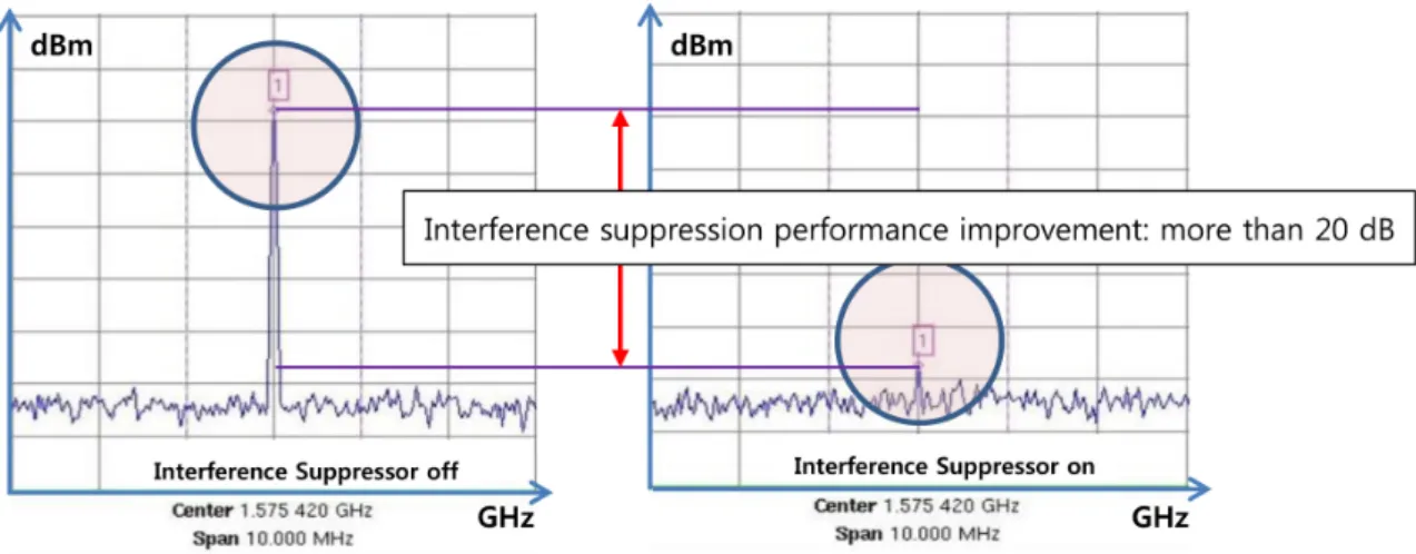
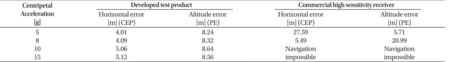
The applications of Global Navigation Satellite System (GNSS) receivers are becoming wider in various commercial and military systems including even small weapon systems such as artillery shells. The precision-guided munitions such as Small Diameter Bomb (SDB) of United States can be used for pinpoint strike by acquiring and tracking GNSS signals in high mobility situation. In this paper, a small GNSS receiver with embedded interference suppression capability working under high dynamic stress is developed which is applicable to the various weapon systems and can be used in other several harsh environments. It applies a kind of matched filter and multiple correlator schemes for fast signal acquisition and tracking of even weak signals and frequency domain signal processing method to eliminate the narrowband interference. To evaluate the performance of the developed GNSS receiver, the test scenario of high mobility and interference environment with the GNSS simulator and signal generator is devised. Then, the signal acquisition time, navigation accuracy, sensitivity, and interference suppression performances under high dynamic operation are evaluated. And the comparison test with the commercial GNSS receiver which has high sensitivity is made under the same test condition.

Keywords: GNSS receiver, interference suppression, fast acquisition

applied to small weapon systems such as artillery shells.

In the United States, for Small Diameter Bomb (SDB) type guided artillery shells which are capable of pinpoint strike in a high mobility condition, a small GPS receiver that has high impact resistance and high mobility characteristics has been developed and applied (Maybaumwisniewski et al. 2005). However, as the application ranges of a GNSS receiver and the dependence have increased, the reliability and availability of a GNSS system have been significantly emphasized. In particular, a GNSS signal system has a certain level of narrowband interference suppression capability based on the application of spread spectrum communication, but it is easily affected by interference signals because the strength of satellite signals received on the ground is very low. There could be various types of interference signals on the ground including unintentional interference signals such as a communication system Received Jan 31, 2015 Revised Feb 24, 2015 Accepted Feb 26, 2015

Corresponding Author

E-mail: [email protected]

Tel: +82-42-363-9256 Fax: +82-42-363-9290

(2)

or a radar system around the GNSS frequency band and intentional interference signals such as a small jammer called Personal Privacy Device, which is used to protect personal privacy and a jammer attack for military purposes.

Therefore, to improve the reliability and availability of a GNSS application system in the presence of these interference signals, a method for improving the inherent interference suppression capability of an existing GNSS navigation system is required. Table 1 summarizes the techniques for strengthening the interference suppression capability of a GNSS receiver (Trinkle & Gray 2001).

It is known that a receiver using C/A code is generally more vulnerable to CW type narrowband interference signals (Kaplan & Hegarty 2006). Thus, an interference suppression technique that can be effectively applied to a small GNSS receiver where the size, weight, and power consumption are limited among receivers using C/A code is the temporal/FFT domain filter method. Also, in the case of the temporal/FFT domain filter method, seamless insertion between an existing GNSS antenna and a receiver is possible. Therefore, in this study, a small GNSS receiver with an embedded interference suppression function based on the implementation of the temporal/FFT domain filter using the Overlapped FFT (OFFT) method was designed and manufactured so that it could be operated in a high mobility environment, and the performance was verified through an experiment. In a high mobility environment where narrowband interference signals are present, a matched filter type fast acquisition (FA) technique and a high sensitivity multimode correlator technique for fast acquisition and tracking of satellite signals and a frequency domain signal processing technique for narrowband interference suppression were applied (Capozza et al. 1999).

A scenario for high mobility condition and narrowband interference environment was made using a GNSS simulator and a signal generator, and the signal acquisition time, navigation accuracy, sensitivity, and the narrowband

interference suppression performance were examined. Also, through a comparison test with an existing high sensitivity commercial GNSS receiver, it was demonstrated that simply increasing the receiving sensitivity cannot guarantee interference suppression performance and navigation performance in a high mobility environment.

2. HARDWARE OF THE GNSS RECEIVER

For the hardware of the GNSS receiver, a small GNSS receiver that is capable of signal processing of the two bands (GPS L1 and GLONASS L1) was implemented. The small GNSS receiver consists of RF board and digital board, as shown in the structure in Fig. 1. The RF board consists of two-channel RF/IF down-conversion ASIC and 14-bit ADC, and the digital board consists of FPGA embedded with a digital interference suppressor module and a correlator module, CPU for navigation algorithm implementation, power circuit, and other Clock and ROM.

2.1 RF Board

In the RF board, RF band satellite navigation signals (GPS L1 and GLONASS L1) received by the antenna are amplified, and they are down-converted to several MHz of IF signal band and are then digitized. For this purpose, the RF board consists of RF ASIC for direct down-conversion and high speed/high performance ADC.

Fig. 1. Structure of the GNSS receiver.

Table 1. Possible interference suppression techniques to standard GPS receiver.

Interference suppression techniques Additional interference suppression Implementation

converter A/D Adaptive A/D Several DB against CW

interferences Need to implemented

internal to GPS receiver

Pre-correlation techniques

Amplitude domain processing 20~40 dB against narrow

band interference Need to be implemented

Either internal or external to GPS receiver Temporal/FFT domain filters

Dual polarization antenna 20~40 dB against narrow band + broadband

interference Spatial filters

Space-time filters

Post-correlation techniques

Adaptive loop bandwidth

3~20 dB against all

interference wave forms Need to be implemented Internal to GPS receiver Data wiping

Open loop carrier tracking

Vector loops

Integration with INS

(3)

To convert GPS and GLONASS RF signals into several around a dozen MHz of IF signals which is the frequency band that can be processed by ADC, frequency down- conversion is required; and for the small GNSS receiver, the RF board was configured using dedicated ASIC for GPS L1/GLONASS L1. This chip amplifies RF signals that enter LNA at the first end of the input. They are then mixed with a local frequency of 1590 MHz through a mixer, and GPS L1 IF (-14.58 MHz) and GLONASS L1 IF (12 MHz) signals are generated. To eliminate image signals from the IF signals, they are passed through Image Rejection Filter and are amplified again. Then, noise other than the bandwidth is eliminated through LPF. The signals are amplified to a sufficient size by IF Amplifier, and are outputted as analog type signals.

To eliminate interference signals that are introduced intentionally or unintentionally, GNSS signals and interference signals that enter RF should be transmitted to FPGA, where the interference suppression algorithm is operated, without distortion or loss. Therefore, RF needs to be implemented based on a device with a high dynamic range; and for the IF analog circuit, high performance multi- bit ADC for the implementation of high linearity needs to be used. Accordingly, for the developed small GNSS receiver, 14 bit 50 Msps ADC was selected and applied to the IF analog circuit.

2.2 Digital Board

The digital board broadly consists of FPGA and CPU, as

shown in Fig. 2. FPGA includes 24-channel tracking module with correlators and an interference suppressor module so that GPS L1 and GLONASS L1 satellite signals can be tracked at the same time by 12 channels, respectively. The interference suppressor module eliminates interference signals that are included in digitized IF GNSS signals transmitted from ADC. Then, measurements for correlation values and a navigation solution are generated, and the satellite signals are tracked. Using the correlation values obtained from FPGA, CPU performs the acquisition/

tracking and computation of navigation algorithm and signals. Also, it performs prompt initialization and high sensitivity signal acquisition functions.

To attenuate interference signals in the GNSS band, the temporal/FFT domain filter was implemented based on the OFFT method. Fig. 3 shows the structure of the OFFT algorithm. In the case of the adaptive filter for Fig. 2. Structure of the digital board.

Fig. 3. Structure of the OFFT algorithm.

Fig. 4. Diagram of the matched filter block.

(4)

interference suppression, FFT and IFFT structure was basically used; and to minimize the power loss of signals, it was implemented as an OFFT structure where a window function and an overlap structure had been added. OFFT is a structure that processes input signals by an N-point block unit. The window function is processed every N-point, and it is converted to frequency domain through FFT. Then, through the statistical processing of each block signal, interference signals are determined, and a threshold value for elimination is established. A frequency component that is larger than the threshold value is regarded as an interference signal and is eliminated, and the signal is restored by performing IFFT (Shin et al. 2006).

In an FA module, the Doppler frequency in the frequency domain is obtained at a Doppler cell, and information in the time domain (code delay) is obtained using a 2048- tap matched filter. Then, this information is sent to each channel, which enables signal acquisition in a short time.

The implemented matched filter was basically based on a general case shown on the left side of Fig. 4. It was implemented so that the tap expansion of the matched filter could be easily performed and the number of gates could be minimized, by conducting a design so that the form of each low-rank module and high-rank module could be recursive.

For the implemented Doppler cell, sinusoidal signals with each different frequency are put into each Doppler cell and it is multiplied by an input signal, unlike general FFT. This implementation method could decrease required gate count;

and during the extraction of frequency domain information on input signals, analysis could be performed based on a unit that is relatively smaller than the entire range.

A multimode correlator was designed for the processing of GPS L1 and GLONASS L1 signals. It includes 24 channels so that a maximum of 24 satellite signals can be processed at the same time. It provides correlation values for the

acquisition and tracking of satellites by processing 14- bit IF signals inputted from the RF board, and generates measurements for obtaining a navigation solution and sends them to the microprocessor.

3. IMPLEMENTATION AND PERFORMANCE EVALUATION OF THE SMALL GNSS

RECEIVER

Fig. 5 shows the test product of the small satellite navigation receiver suggested in this study. The RF and digital boards were manufactured to be circular boards, and parts were mounted on both sides of each board for the optimal use of space. The maximum operation speed was 900 m/s, and TCXO, which is resistant to impact, was used.

Each board was molded and coated so that it could endure high impact.

3.1 High Mobility Simulation Results of the Developed Test Product

To perform a high mobility simulation of the developed test product, the simulation environment was organized as shown in the left figure of Fig. 6, and the right figure Fig. 5. Developed GNSS receiver with enhanced interference suppression and high dynamic capability.

Fig. 6. Developed GNSS receiver with enhanced interference suppression and high dynamic capability.

(5)

shows the simulation scenario. To consider only the high mobility characteristics of the developed test product, other error factors were not applied in the scenario. Also, the centripetal acceleration of a flight vehicle that performs a circular motion around a circle with a radius of several km at 500 m/s in a condition where interference signals are not applied was changed, and the resultant required time for initial navigation (hot start), navigation errors (horizontal error and altitude error), and sensitivity (acquisition and tracking) were measured. Table 2 summarizes the results of the navigation performance test in a high mobility environment. As the centripetal acceleration increased, the required time for initial navigation and the navigation errors increased, but a certain level of performance standard was continuously satisfied. Table 3 summarizes the sensitivity performance depending on the changes in the centripetal acceleration in a high mobility environment. As the

centripetal acceleration increased, the sensitivity decreased.

It was found that navigation could be maintained in a high mobility environment by lowering the sensitivity performance compared to that of an existing high sensitivity receiver.

3.2 Measurement of the Narrowband Interference Suppression Performance of the Developed Test Product

To measure the narrowband interference suppression performance of the test product suggested in this study in a high mobility environment, an experiment environment where narrowband interference signals are applied was established using a GPS L1/GLONASS L1 simulator and a signal generator, as shown in Fig. 7. In the experiment, the same high mobility environment scenario described in Section 3.1 was used, and other error factors were excluded to examine only the high mobility characteristics and interference suppression performance of the test product.

For the interference signals, narrowband interferences (CW) with the center frequencies of GPS L1 (1575.42 MHz) and GLONASS L1 (1602 MHz) were generated using the signal generator; and for the level of the applied interference signals, the cable loss between signal generator and Table 3. Results of the sensitivity test in a high mobility environment (developed

test product).

Centripetal acceleration

[g]

Sensitivity Tracking

[dBm] Acquisition (Hot start) [dBm]

5 8 10 15

-141 -140 -140 -139

-139 -138 -139 -136

Table 2. Results of the navigation performance test in a high mobility environment (developed test product).

Centripetal acceleration

[g]

Hot start [sec]

Navigation error Horizontal

error [m] (CEP) Altitude error [m] (PE) 5

8 10 15

2.76 4.78 6.42 8.1

4.01 4.09 5.06 5.12

8.24 8.32 8.64 8.56

Fig. 7. Interference suppression performance test environment in a high mobility environment.

Table 4. Interference suppression performance in a high mobility environment (developed test product).

Centripetal acceleration

[g]

CW (GPS L1, 1575.42 MHz)

CW (GLONASS L1, 1602 MHz) Interference suppression performance improvement [dB]

1 5 8 10 15

≥20 ≥20

(6)

the simulator was reflected by measuring it in advance.

Table 4 summarizes the improvement in the narrowband interference suppression performance depending on the presence of the interference suppression function. For the performance measurement, maintaining 3D navigation in a condition where interference signals are applied was used as the criterion. Fig. 8 shows the change in the spectrum wave form depending on the presence of the interference suppression function. In the case of the interference suppression capability in a high mobility environment based on the test of the developed test product, for the GPS L1 band, a J/S performance improvement of more than 20 [dB] could be obtained compared to when the interference suppression function was off; and for the GLONASS L1 band, the J/S performance was also improved by more than 20 [dB].

3.3 High Mobility Simulation of a Commercial High Sensitivity Receiver

It is known that a commercial high sensitivity GNSS receiver generally has superior narrowband interference suppression capability compared to a general GNSS receiver due to the sensitivity characteristics. The receiver suggested in this study and a commercial high sensitivity GNSS receiver were tested using the same scenario, and the navigation performance and interference suppression performance were examined. The commercial receiver used for the simulation was EVK-6T (Ublox, Inc.), and the major specifications on the data sheet are summarized in Table 5.

Tables 6 and 7 summarize the results of the high mobility test of the commercial receiver. For the navigation performance and sensitivity test in a high mobility

environment, the performance measurement was conducted while changing the centripetal acceleration without applying CW interference signals, as shown in Fig.

6. The test of the commercial receiver showed that the high sensitivity characteristics and navigation accuracy were maintained when it was at a standstill or there was almost no acceleration. However, when the acceleration was about 5 g, the navigation error approximately doubled compared to that in a standstill condition, and the sensitivity characteristics also deteriorated by more than 15 dB; and when the acceleration was more than 10 g, navigation could not be performed. According to the specification, the commercial high sensitivity receiver used for the simulation is to guarantee the performance only when the applied centripetal acceleration is less than 4 g. Therefore, it was confirmed that the commercial receiver provided high sensitivity performance in almost standstill condition.

However, in high mobility conditions where the applied acceleration was more than 4 g, the navigation accuracy deteriorated significantly even though the navigation was Fig. 8. Diagram of the matched filter block.

Table 6. Results of the navigation performance test in a high mobility environment (commercial receiver).

Centripetal Acceleration

[g]

Hot start [sec]

Navigation error Horizontal error

[m] (CEP) Altitude error [m] (PE) 5

8 10 15

2.75 2.87 Navigation impossible

27.59 5.49 Navigation impossible

5.71 20.99 Navigation impossible Table 5. Major specifications of the commercial receiver.

Category Specification Remark

Tracking sensitivity [dBm]

Acquisition sensitivity [dBm]

Hot start [sec]

Horizontal position accuracy [m]

-162 -162 1

≤2.5

Demonstrated with a good active antenna

Without aiding

Without aiding

(7)

maintained or the navigation could not be performed. From the above test result, it is confirmed the sensitivity and dynamic capability are, to some extent, a trade off against each other. The commercial receiver used for the test does not provide a CW interference suppression function in the GLONASS L1 band. Thus, the interference suppression capability was evaluated by the possibility of navigation when CW in the GPS L1 band was applied in a high mobility condition. Table 8 summarizes the results. The results of the test showed that during the application of CW, when a centripetal acceleration of 1~8 g was applied, the navigation accuracy deteriorated but navigation was maintained with

less than five satellites; and when a centripetal acceleration of more than 10 g was applied, navigation could not be performed.

3.4 Performance Comparison of the Developed Test Product and the Commercial High Sensitivity Receiver

In this section, the performances of the test product suggested in this study and the commercial high sensitivity receiver were compared based on the aforementioned test results. Tables 9 and 10 summarize the navigation performance and sensitivity performance depending on the changes in the centripetal acceleration. For the commercial high sensitivity receiver, deteriorations in the navigation performance and sensitivity performance became worse as the centripetal acceleration increased, and navigation was impossible when the centripetal acceleration was more than 10 g. In contrast, for the developed test product, navigation was maintained even when the centripetal acceleration was increased to 15 g, and it showed superior navigation performance compared to the commercial receiver. Table 11 summarizes the interference suppression performances in a high mobility environment. The high mobility/interference suppression receiver suggested in this study showed an anti-jamming performance improvement of more than 20 dB even in a high mobility condition where CW of GPS L1 (1575.42 MHz) and GLONASS L1 (1602 MHz) was applied.

Table 9. Comparison of the navigation performances in a high mobility environment..

Centripetal Acceleration

[g]

Developed test product Commercial high sensitivity receiver

Horizontal error [m] (CEP)

Altitude error [m] (PE)

Horizontal error [m] (CEP)

Altitude error [m] (PE) 5

8 10 15

4.01 4.09 5.06 5.12

8.24 8.32 8.64 8.56

27.59 5.49 Navigation impossible

5.71 20.99 Navigation impossible

Table 10. Comparison of the sensitivity performances in a high mobility environment.

Centripetal acceleration [g]

Developed test product Commercial high sensitivity receiver

Tracking [dBm] Acquisition [dBm] Tracking [dBm] Acquisition [dBm]

5 8 10 15

-141 -140 -140 -139

-139 -138 -139 -136

-145 -139 Navigation impossible

-144 -137 Navigation impossible

Table 11. Comparison of the interference suppression performances in a high mobility environment.

Centripetal acceleration

(g)

CW (GPS L1, 1575.42 MHz) CW (GLONASS L1, 1602 MHz)

Developed test product

Commercial high sensitivity receiver

Developed test product

Commercial high sensitivity receiver 1

5 8

Navigation possible (Interference suppression performance improvement:

more than 20 dB)

Navigation possible Navigation possible (Interference suppression performance improvement:

more than 20 dB)

GLONASS not supported 10

15 Navigation impossible

Table 8. Results of the navigation possibility test during the application of high mobility / CW interference (commercial receiver).

Centripetal acceleration [g]

CW (GPS L1, 1575.42 MHz)

CW (GLONASS L1, 1602 MHz) 1

5

8 Navigation possible

GLONASS not supported 10

15 Navigation impossible

Table 7. Results of the sensitivity test in a high mobility environment (commercial receiver).

Centripetal acceleration

[g]

Sensitivity Tracking

[dBm] Acquisition(Hot start) [dBm]

5 8 10 15

-145 -139 Navigation impossible

-144

-137

Navigation

impossible

(8)

4. CONCLUSIONS

In this study, a small GNSS receiver that is embedded with a narrowband interference suppression function and can be operated in a high mobility environment was developed, and the performance was verified. For the interference suppression function, a temporal/FFT domain filter, which can be embedded in a small GNSS receiver and can eliminate CW interference signals (to which a C/A code receiver is the most vulnerable) in the most favorable method in terms of electric power and size, was implemented based on the OFFT method.

The performance of the test product of the suggested receiver was verified in test scenario conditions with various dynamic characteristics, and it was found that the interference suppression performance of the suggested receiver was improved by more than 20 dB even in a high mobility environment in relation to CW interference signals.

In particular, through a comparison test with a commercial high sensitivity GNSS receiver, it was found that the test product suggested in this study can be applied to operation fields with a high mobility dynamic characteristic (e.g., SDB) to which the commercial high sensitivity receiver cannot be applied due to the limitation in the dynamic characteristic and the lack of interference suppression performance.

REFERENCES

Capozza, P. T., Holland, B. J., Hopkinson, T. M., Li, C., Moulin, D., et al. 1999, Measured effects of a narrowband interference suppressor on GPS Receivers, in 1999 ION 55th Annual Meeting, Cambridge, MA, 28- 30 June 1999.

Kaplan, E. D. & Hegarty, C. J. 2006, Understanding GPS:

Principles and Applications, 2nd ed. (Norwood, MA:

Artech House, Inc.)

Maybaumwisniewski, S., Brown, S., & Kreitler, W. 2005, Weapons. A Report on the Industry, the Industrial College of the Armed Forces National Defense University, Industry Study 5240-11

Shin, M. Y., Park, C. S., Lee, H.-K., Lee, D.-Y., Hwang, D.- H., et al. 2006, A Narrowband Interference Excision Algorithm in Frequency Domain for GNSS Receivers, in 2006 IAIN/GNSS, Jeju, Korea, Oct 2006.

Trinkle, M. & Gray, D. 2001, GPS Interference Mitigation:

O ve r v i e w a n d E x p e r i m e nt a l Re su l t s, i n 2 0 0 1 Proceedings of the 5th International Symposium on Satellite Navigation, Canberra, Australia, pp.1-14

Yong-Hyun Park received the B.S. and M.S.

degree in electronics engineering from Chungbuk National University, Korea in 2010, and 2013. He is an Associate Engineer of Navcours. His research interests include GNSS, Interference Suppression, AJ.

Sung-Wook Moon received the Ph.D. degree in electronics engineering from Chungnam National University, Korea in 2002. He was a Chief Engineer of Navcours. His research interests include GNSS, Interference Suppression.

Bong-Gyu Shin received the M.S. degree in electric wave engineering from Kwangwoon University, Korea. He is a Senior Engineer of HanHwa. His research interests include GPS and RF.

Jong-Su Oh received the Ph.D. degree in

mechanical design engineering from

Chungnam National University, Korea in

1995. He was a Principal Researcher of

Agency for Defense Development. His

research interests include Fuse of Munition.

수치

Table 1.  Possible interference suppression techniques to standard GPS receiver.
Fig. 4.  Diagram of the matched filter block.
Fig. 6.  Developed GNSS receiver with enhanced interference suppression and high dynamic capability.
Table 2.  Results of the navigation performance test in a high mobility  environment (developed test product).
+3

참조

관련 문서

In this study, friction welding was applied to carbon steel tubes at a high speed condition to achieve an eco-friendly welding process and a superior

In this study, the reliability of high efficiency air conditioning compressor applied with high vacuum local pressure die casting technique is to be analyzed through

In this study, we found that Pin1 plays a pivotal role in insulin- induced AP-1 activation through its interaction with p70S6K and prolongs activity of

This work builds inversely a base performance model of a turboprop engine to be used for a high altitude operation UAV using measured performance data,

As a result we should improve the potential that HVPE with high growth rate can become a new AlN crystal growth method because the high-quality

In particular, a recent study showed that intrathecal SOG administration has an antinociceptive effect in a formalin test of rat model and shows the possibility of

As a result of the analysis of the MKT test sheet, the CCK(Common Content Knowledge) of the preparatory mathematics teacher was confirmed as a high

The function of the channel encoder is to introduce, in a controlled manner, some redundancy in the binary information sequence at the receiver.. It is