Influence of the implant-abutment connection design and diameter on the screw joint stability
Hyon-Mo Shin1, Jung-Bo Huh1, Mi-Jeong Yun1, Young-Chan Jeon1, Brian Myung Chang2, Chang-Mo Jeong1*
1Department of Prosthodontics, Dental Research Institute, Pusan National University, Yangsan, Republic of Korea
2Head and Neck Institute, Cleveland Clinic, Cleveland, Ohio, USA
PURPOSE. This study was conducted to evaluate the influence of the implant-abutment connection design and diameter on the screw joint stability. MATERIALS AND METHODS. Regular and wide-diameter implant systems with three different joint connection designs: an external butt joint, a one-stage internal cone, and a two-stage internal cone were divided into seven groups (n=5, in each group). The initial removal torque values of the abutment screw were measured with a digital torque gauge. The postload removal torque values were measured after 100,000 cycles of a 150 N and a 10 Hz cyclic load had been applied. Subsequently, the rates of the initial and postload removal torque losses were calculated to evaluate the effect of the joint connection design and diameter on the screw joint stability. Each group was compared using Kruskal-Wallis test and Mann-Whitney U test as post-hoc test (α=0.05).
RESULTS. The postload removal torque value was high in the following order with regard to magnitude: two-stage internal cone, one-stage internal cone, and external butt joint systems. In the regular-diameter group, the external butt joint and one-stage internal cone systems showed lower postload removal torque loss rates than the two-stage internal cone system. In the wide-diameter group, the external butt joint system showed a lower loss rate than the one-stage internal cone and two-stage internal cone systems. In the two-stage internal cone system, the wide- diameter group showed a significantly lower loss rate than the regular-diameter group (P<.05). CONCLUSION. The results of this study showed that the external butt joint was more advantageous than the internal cone in terms of the postload removal torque loss. For the difference in the implant diameter, a wide diameter was more advantageous in terms of the torque loss rate. [J Adv Prosthodont 2014;6:126-32]
KEY WORDS: Postload removal torque value; External butt joint connection; Internal connection; Platform switching
INTRODUCTION
One of the most common mechanical problems in implant prostheses is the joint loosening and fracture that occur in the screw joint portion between the implant fixture and the abutment.1,2 Joint loosening, along with the mechanical fail-
ure of the implant prosthesis, may cause biological compli- cations such as tissue inflammation around the implants, gingival growth, and fistula formation. In particular, joint loosening in an implant treatment restored with the con- cept of immediate loading may cause harmful stress to the alveolar bone prior to the osseointegration, leading to the failure of the osseointegration.3
The fixture-abutment connection type for the implant system, which is widely used in clinical practice at present, is mainly classified into the external butt joint and the inter- nal cone.
In the external butt joint connection type, stress is mainly applied to the abutment screw when a bending force is applied to the superstructure. In the internal cone con- nection type, the load is mainly transferred via the internal slope of the fixture. Such difference in the load transfer mechanism has been known to affect the stability of the implant connection part.4-8 In general, unlike the external butt joint that requires a second surgery after fixture instal-
Corresponding author:
Chang-Mo Jeong
Department of Prosthodontics, School of dentistry, Pusan National University, Beomeo-ri, Mulgeum-eup, Yangsan, 626-870, Republic of Korea Tel. 82 55 360 5130: e-mail, [email protected]
Received December 6, 2012 / Last Revision October 18, 2013 / Accepted January 17, 2014
© 2014 The Korean Academy of Prosthodontics
This is an Open Access article distributed under the terms of the Creative Commons Attribution Non-Commercial License (http://creativecommons.
org/licenses/by-nc/3.0) which permits unrestricted non-commercial use, distribution, and reproduction in any medium, provided the original work is properly cited.
This study was supported by 2013 Clinical Research Grant, Pusan National University Dental Hospital.
lation, the internal cone has one-stage products that expose the collar, which is the membrane-penetrating region of the fixture, as well as two-stage products. The advantages of the two-stage implant are that it predicts a more esthetic outcome in the anterior region, protects the fixture from external force during the osseointegration, and manufac- tures a temporary denture in the case of poor bone quality.9 On the other hand, the advantages of the one-stage implant are that it does not require a second surgery, there is no microgap between the fixture and the abutment in the subgingival region, and the fulcrum length from the joint connection to the load point is short.10-14
The implant diameter should be selected by considering the teeth defect pattern, depth and width of the residual alveolar bone, rehabilitation space, emergence profile, and occlusion. Implants with wide diameters are mainly used in cases of insufficient edentulous bone height, failure of osseointegration, or required reinstallation due to fixture fracture. Due to the advantages of wide-diameter implants, however, such as the emergence profile improvement, increased contact area between the fixture and the alveolar bone, increased fracture resistance, and wide stress distribu- tion, it is clinically preferred in the posterior region, which has a wide bone width.15-17
On the other hand, the platform-switching concept is a method that uses a regular abutment in a fixture with a wide diameter. The conduct of platform-switching on implants with external butt joint connections has been known to minimize marginal bone absorption resulting in gingival recession and interdental papilla loss, which com- monly occur after abutment fastening by placing the fix- ture-abutment connection part that is a route of bacterial invasion, more internally via the use of a fixture larger than the abutment.18-21
The aforementioned implant systems that are currently used in clinical practice have various connection types and
various diameters of their fixtures, abutments, and abut- ment screws. Unfortunately, studies on the effect of such factors on the stability of the connection part associated with screw loosening have rarely been conducted.
Accordingly, this study was conducted to investigate the effect of the implant-abutment connection design and diameter on the screw joint stability in implant systems with a two-stage external butt joint and one- and two-stage internal cones by comparing the removal torque loss of the abutment screw after repeated loads.
MATERIALS AND METHODS
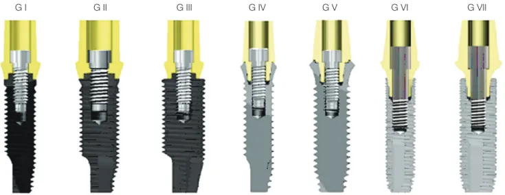
In this study, the USII system with an external butt joint, the SSII system with a one-stage 8o internal cone, and the GSII system with a two-stage 11o internal cone from Osstem Implant (Osstem, Pusan, Korea) were used (Fig. 1).
A fixture with two types of diameter was used in each sys- tem. A cement-retained abutment and WC/CTa (coated with tungsten carbide/carbon) screws were used (Table 1 and Table 2). A fixture with a 1.8 mm-high collar was used in the one-stage implant SSII system, and an abutment with a 2.0 mm-high collar was used in the other systems to maintain the same height at the load point. The subjects were divided into a total of seven groups according to the abutment-fixture connection type and diameter, including platform-switching type samples that used a regular abutment in their fixture with a wide diameter in the USII system.
The implant fixture was fixed to the separately manufac- tured jig, and the abutment was fastened to the implant.
Then a 30 Ncm tightening torque was applied to each abut- ment screw using a digital torque gauge (MGT12E, MARK-10 Co., Hicksville, NY, USA) for standardization according to the manual of each manufacturer. Ten minutes later, the same tightening torque was applied again to com- pensate for the preload loss due to the surface sinking.
Fig. 1. Sectional views of the implant fixture, abutment, and abutment screw assemblies. More detail features was in Table 1 and Table 2.
G I G II G III G IV G V G VI G VII
Then the removal torque of each abutment screw was mea- sured using a digital torque gauge. To minimize the change in the removal torque due to the repeated fastening, a total of 35 fixtures, abutments, and abutment screws were used in each system (five per experiment group).
The implant fixture was fixed to jig in a repeated load device (Instron 8841, Instron Co., England), and the abut- ment was fastened with an abutment screw by applying a 30 Ncm tightening torque, as in the measurement of the initial removal torque. Then, a machined stainless steel metal tube with disc shape was attached to abutment using a resin- class temporary cement (Premier Implant Cement, Premier Dental Products Co., La Vista, NE, USA) (Fig. 2).
A sine-type repeated load with a maximum 150 N, a minimum 10 N, and a 10 Hz cycle was applied to the metal tube, 5 mm away from the center axis of the implant. Then, 104 cycles and a 30 Ncm tightening torque were applied again for the simulation of more actual clinical situations.
With the same method, 105 cycles of repeated load were applied, and the removal torque was measured using a digi- tal torque gauge. The removal torque loss was calculated according to the following formula.
Postload Removal Torque Loss (%) = [(Initial Removal Torque Value – Postload Removal Torque value) / Initial Removal Torque Value] × 100
Table 1. Features of the experimental implant fixtures
Group Implant system Diameter (mm) Interface Platform
I USII regular 4.0 External hex butt joint 2.7 mm hexagon
II USII wide 5.0 External hex butt joint 3.4 mm hexagon
III USII T-wide 5.0 External hex butt joint 2.7 mm hexagon
IV SSII regular 4.1 8° Morse taper 2.9 mm octagon
V SSII wide 4.8 8° Morse taper 2.9 mm octagon
VI GSII standard 4.0 11° Morse taper 2.5 mm hexagon
VII GSII standard 5.0 11° Morse taper 2.5 mm hexagon
Table 2. Features of the experimental implant abutments and abutment screws
Group Abutment Screw
Diameter (mm) Collar height (mm) Abutment height (mm) Composition (Coating) Diameter (mm)
I 5.0
2.0
(G IV, V: no collar) 5.5 Ti-6Al-4Va (coated with tungsten carbide / carbon)
2.0
II 6.0 2.5
III 5.0 2.0
IV 4.8 2.0
V 6.0 2.0
VI 5.0 2.0
VII 6.0 2.0
Fig. 2. Schematic diagram of testing conditions.
11.0 mm
3.0 mm
5.0 mm
Load
Statistical analysis was performed using SPSS ver. 18.0 (SPSS, Chicago, IL, USA). To analyze measurements taken at each group were compared using Kruskal-Wallis test.
When the Kruskal-Wallis test was statistically significant, multiple comparison analysis was performed as a post-hoc test, using the Mann-Whitney U test. Values of P<.05 were taken to indicate statistical significance.
RESULTS
The mean and standard deviation of the removal torque before and after the load in each implant system was pre- sented in Table 3. The initial removal torque was higher in Group II than in Group VII (P<.05), and no significant dif- ference was found among the other groups (P>.05). The postload removal torque was highest to lowest in the regu- lar-diameter comparison (P<.05) in the following groups, in this order: VI, IV, and I; and in the wide-diameter compari- son (P<.05) in this order: VII, V, and II. No significant dif- ference was found between Group III and Group II in the USII system (P>.05). The different lowercase superscript letters in the initial and uppercase superscript letters in the postload are significantly different (P<.05).
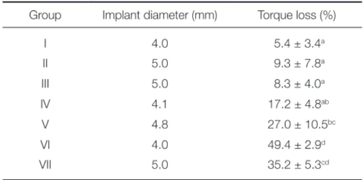
The mean and standard deviation of the removal torque loss in each system before and after the load are presented in Table 4. For the regular diameter, the postload removal torque loss was higher in Group VI than in Groups I and IV (P<.05), but no significant difference was found between Group I and Group IV (P>.05). For the wide diameter, the removal torque loss was higher in Groups V and VII than in Group II (P<.05), but no significant differ- ence was found between Group V and Group VII (P>.05).
In the comparison of the implant diameters, the postload removal torque loss was higher in Group VI than in Group VII (P<.05), but no significant difference in the removal torque loss was found among the other groups (P>.05). In addition, there was no significant difference between Group III and Group II in the USII system (P>.05). The different lowercase superscript letters in the torque loss denote significant differences (P<.05).
DISCUSSION
Screw loosening is caused by an inappropriate tightening torque, the surface sinking phenomenon, screw deforma- tion and preload loss due to overload, and vibration due to the functional load.22 The preload, which is a compressed force that occurs between the abutment and the fixture due to the tightening torque, increases as the tightening torque increases and the friction coefficient of the screw decreas- es.23 If the tightening torque is applied to the abutment screw, or if the external load is applied to the implant superstructure, the surface roughness wear is smoothened due to the compressed force. This settling effect reduces the preload, which leads to screw loosening.24 To compen- sate for the preload loss caused by surface sinking in actual clinical practice, the tightening torque must be applied again 10 minutes after a new screw is fastened, and the tightening torque must be regularly and repeatedly applied after the functioning of the implant prosthesis.25 In this study, based on previous reports, the tightening torque was repeatedly applied 10 minutes after the screw was fastened, and after 10,000 cycles of repeated loads to compensate for the sur- face sinking caused by the functional load.
For the external butt joint connection type, the stress caused by all the external loads, except for the tightening torque and the load of the implant major axis, is applied to the screw.8 The external hexagon of the external butt joint was developed to provide the abutment direction upon the fixture installation and the superstructure manufacturing, and it was difficult to achieve resistance against the lateral force. In addition, the fulcrum length for the lateral force was longer compared to the internal cone connection type, and most external hexagons have a gap in the hexagon between the abutment and the fixture, and mainly depend on the friction caused by the preload for the torsion stress.
Therefore, it is very important to apply the appropriate pre- load to stabilize the connection parts in the external butt joint.26-29
On the other hand, in the internal-cone-connection- type implant system, the tightening torque is driven by not
Table 3. Mean value ± SD of the initial and postload removal torques (Ncm)
Group Implant diameter (mm) Initial Postload
I 4.0 26.0 ± 0.8abc 24.6 ± 1.5C
II 5.0 28.3 ± 1.4c 25.6 ± 1.6C
III 5.0 26.5 ± 1.4abc 24.2 ± 0.7C
IV 4.1 25.1 ± 1.1ab 20.8 ± 0.7B
V 4.8 26.8 ± 0.4bc 19.5 ± 2.6B
VI 4.0 24.8 ± 0.9ab 12.5 ± 0.6A
VII 5.0 24.1 ± 0.9a 15.6 ± 1.1A
Within the same column, the means with the same superscript letters are not statistically different from one another (P>.05).
Table 4. Mean rate ± SD of the postload removal torque loss (%)
Group Implant diameter (mm) Torque loss (%)
I 4.0 5.4 ± 3.4a
II 5.0 9.3 ± 7.8a
III 5.0 8.3 ± 4.0a
IV 4.1 17.2 ± 4.8ab
V 4.8 27.0 ± 10.5bc
VI 4.0 49.4 ± 2.9d
VII 5.0 35.2 ± 5.3cd
Within the same column, the means with the same superscript letters are not statistically different from one another (P>.05).
only the screw height but also the wedge effect due to the conical abutment sinking, and the load is mainly supported by the internal slope of the fixture. Therefore, the stress that occurs in the abutment screws has been known to be relatively smaller than that in the external butt joint.8 In the internal cone implant system, however, the tensile force of the abutment screw, that is, the preload, was reported to have been slightly reduced due to the slight sinking of the abutment caused by the vertical component of the load. In the external butt joint implant system, the preload loss was reported to have been relatively smaller due to the vertical support of the upper fixture.8
Despite the same internal cone connection type, in the SSII system that was used in this study, unlike in the GSII system, as the upper shoulder of the fixture collar came in contact with the superstructure, and thus acquired addition- al support against the vertical load, the abutment sinking became relatively restricted. In this study, however, the load support effect of the aforementioned shoulder was not achieved due to the different study method. Therefore, this restriction should be considered when the results of this study are interpreted.
The preload, which is a contributing factor to the stabil- ity of the screw connection parts, is affected by various fac- tors associated with the elongation of the abutment screw.
The measurement of the removal torque of the abutment screw is one of the methods for indirect comparison of preloads. By measuring the initial removal torque, the reductions in the degree of the preload caused by the tight- ening torque can be compared. The factors that affect the initial removal torque include friction, surface sinking, and abutment sinking. By measuring the removal torque and calculating the loss rate after the repeated loads that are clinically more important, the reduced preloads due to the external load, that is, the joint stability against the function- al load, can be indirectly compared. The joint stability against the functional load is affected by the surface sinking of the implant system, the joint micro-movement, the abut- ment screw deformation, and the abutment sinking.
In this study, the initial removal torque was higher in the USII system than in the GSII and SSII systems for both the regular and wide diameters. This is because more preload might have been occurred in the USII system with the external butt joint connection type, which may have led to increased friction. The compressed force was higher in the external butt joint, wherein the tightening torque was main- ly converted into the compressed force via the screw elon- gation, than in the internal cone when the same torque was applied.30
On the other hand, unlike previous study results in which the joint stability was superior in the internal cone than in the external butt joint,31,32 the postload removal torque loss was lowest in the USII system for both the reg- ular and wide diameters, and increased in the order of the SSII system and the GSII system, although the difference was not statistically significant. The aforementioned differ- ence in the results is likely to be attributable to the experi-
mental devices or load point and differences in the load condition such as the repeated load number. Further verifi- cation is required. In this study, the high removal torque loss in the internal cone connection type was mainly attrib- utable to the preload loss caused by the abutment sinking.
The removal torque loss was lower in the SSII system than in the GSII system, although both systems were of the internal cone connection type. The aforementioned result is likely to be attributable to the one-stage implant with a 1.8 mm collar reduced fulcrum length.
Theoretically, if the implant system diameter increases, the preload loss caused by the bending load during the functional movement relatively decreases due to the increased area between the abutment and the fixture. It was reported that the joint opening due to the fulcrum load was lower in the wide-diameter implant system than in the regu- lar-diameter implant system in a repeated load experiment in which a strain gauge was used.33 When the fulcrum load at the upper fixture was applied to a 10 mm-tall metal tube, the external force that was applied to the abutment screw was calculated in the moment form using the following for- mula.34
Fs = [(Fh× 10) – (Fv× Lv)] / (0.5 × d)
wherein Fs is the external force applied to the abutment screw, Fh is the horizontal component of the load, Fv is the vertical component of the load, Lv is the distance from the vertical component of the load to the fulcrum point, and d is the fixture diameter.
Theoretically, the external force applied to the abutment screw decreases as the fixture diameter increases. In the comparison of the implant diameters in this study, no sig- nificant difference in the postload removal torque loss was found between the USII and SSII systems. The reason for the lack of reduction of the loss in the USII and SSII sys- tems despite the increased diameter is unclear. In this study, a 30 Ncm tightening torque was applied in the USII system with a wide diameter, as in the other test groups, despite its larger abutment screw diameter. If the abutment screw diameter increases, relatively less screw elongation could occur when the same tightening torque is applied.
Therefore, it is likely that the preload loss due to the sur- face sinking caused by the tightening torque and the repeat- ed load could occur more in the wide-diameter implant sys- tem with less screw elongation, and result in the partial removal of the moment reduction effect caused by the increased diameter. The relatively increased lateral wall thickness is likely to be attributable to the reduction in the removal torque loss in the wide-diameter GSII system.
Platform-switching has been reported to reduce margin- al bone resorption by concentrating the stress more inter- nally during the dynamic function,17 in addition to the bio- logical effects that are achieved by placing the fixture-abut- ment connection more internally.35 The results of this study showed, however, no significant differences in the removal torque and the loss rate after repeated loads between
Group III, which corresponded to the platform-switching USII system, and Group II, which corresponded to the wide-diameter USII system. The aforementioned result indicates that no significant difference in the external force applied to the abutment screw was found, as platform- switching uses an abutment with the same diameter shown in a finite element analysis,36 in which no significant differ- ences in the stress distribution and the joint opening were found according to the platform-switching.
In this study, the screw joint stability was indirectly compared via the removal torque loss after repeated loads.
Unlike in the external butt joint wherein the joint stability is wholly maintained by the preload caused by the tensile force of the abutment screw, the internal cone connection type achieved additional joint stability from the wedge effect caused by the abutment sinking and the screw pre- load. Therefore, it is more appropriate to interpret the results of this study by restricting them to the screw loos- ening of the abutment rather than to directly associating them with the clinical failure of the fixture-abutment con- nection. In addition, a further comparative study on the wedge effect of the internal-cone-connection-type on the joint stability is required.
CONCLUSION
In this study, the results of this study showed that the external butt joint was more advantageous than the internal cone in terms of the postload removal torque loss. For the difference in the implant diameter, a wide diameter was more advantageous in terms of the torque loss rate. The results of this study showed that the implant-abutment connection design and diameter affect the screw joint sta- bility. As preload loss due to the functional load could occur in any implant system, regular examination and the re-torque process for an appropriate tightening torque are required.
REFERENCES
1. Ekfeldt A, Carlsson GE, Börjesson G. Clinical evaluation of single-tooth restorations supported by osseointegrated im- plants: a retrospective study. Int J Oral Maxillofac Implants 1994;9:179-83.
2. Jemt T, Lekholm U, Gröndahl K. 3-year followup study of early single implant restorations ad modum Brånemark. Int J Periodontics Restorative Dent 1990;10:340-9.
3. Misch CE, Wang HL, Misch CM, Sharawy M, Lemons J, Judy KW. Rationale for the application of immediate load in im- plant dentistry: Part I. Implant Dent 2004;13:207-17.
4. Rangert B, Jemt T, Jörneus L. Forces and moments on Branemark implants. Int J Oral Maxillofac Implants 1989;4:
241-7.
5. Dixon DL, Breeding LC, Sadler JP, McKay ML. Comparison of screw loosening, rotation, and deflection among three im- plant designs. J Prosthet Dent 1995;74:270-8.
6. Levine RA, Clem DS 3rd, Wilson TG Jr, Higginbottom F,
Solnit G. Multicenter retrospective analysis of the ITI im- plant system used for single-tooth replacements: results of loading for 2 or more years. Int J Oral Maxillofac Implants 1999;14:516-20.
7. Levine RA, Clem DS 3rd, Wilson TG Jr, Higginbottom F, Saunders SL. A multicenter retrospective analysis of the ITI implant system used for single-tooth replacements: prelimi- nary results at 6 or more months of loading. Int J Oral Maxillofac Implants 1997;12:237-42.
8. Chee W, Felton DA, Johnson PF, Sullivan DY. Cemented ver- sus screw-retained implant prostheses: which is better? Int J Oral Maxillofac Implants 1999;14:137-41.
9. Merz BR, Hunenbart S, Belser UC. Mechanics of the im- plant-abutment connection: an 8-degree taper compared to a butt joint connection. Int J Oral Maxillofac Implants 2000;
15:519-26.
10. Friberg B, Sennerby L, Linden B, Gröndahl K, Lekholm U.
Stability measurements of one-stage Brånemark implants during healing in mandibles. A clinical resonance frequency analysis study. Int J Oral Maxillofac Surg 1999;28:266-72.
11. Wilson TG, Kornman KS. Fundamentals of periodontics.
Chicago; Quintessence; 2003. p. 582.
12. Persson LG, Lekholm U, Leonhardt A, Dahlén G, Lindhe J.
Bacterial colonization on internal surfaces of Brånemark sys- tem implant components. Clin Oral Implants Res 1996;7:90- 5.
13. Scarano A, Assenza B, Piattelli M, Iezzi G, Leghissa GC, Quaranta A, Tortora P, Piattelli A. A 16-year study of the mi- crogap between 272 human titanium implants and their abut- ments. J Oral Implantol 2005;31:269-75.
14. King GN, Hermann JS, Schoolfield JD, Buser D, Cochran DL. Influence of the size of the microgap on crestal bone levels in non-submerged dental implants: a radiographic study in the canine mandible. J Periodontol 2002;73:1111-7.
15. Dibart S, Warbington M, Su MF, Skobe Z. In vitro evaluation of the implant-abutment bacterial seal: the locking taper sys- tem. Int J Oral Maxillofac Implants 2005;20:732-7.
16. Degidi M, Piattelli A, Carinci F. Clinical outcome of narrow diameter implants: a retrospective study of 510 implants. J Periodontol 2008;79:49-54.
17. Langer B, Langer L, Herrmann I, Jorneus L. The wide fix- ture: a solution for special bone situations and a rescue for the compromised implant. Part 1. Int J Oral Maxillofac Implants 1993;8:400-8.
18. Lazzara RJ, Porter SS. Platform switching: a new concept in implant dentistry for controlling postrestorative crestal bone levels. Int J Periodontics Restorative Dent 2006;26:9-17.
19. Prosper L, Redaelli S, Pasi M, Zarone F, Radaelli G, Gherlone EF. A randomized prospective multicenter trial evaluating the platform-switching technique for the prevention of postrestorative crestal bone loss. Int J Oral Maxillofac Implants 2009;24:299-308.
20. Berglundh T, Lindhe J, Ericsson I, Marinello CP, Liljenberg B, Thomsen P. The soft tissue barrier at implants and teeth.
Clin Oral Implants Res 1991;2:81-90.
21. Abrahamsson I, Berglundh T, Wennström J, Lindhe J. The peri-implant hard and soft tissues at different implant sys-
tems. A comparative study in the dog. Clin Oral Implants Res 1996;7:212-9.
22. Tarnow DP, Cho SC, Wallace SS. The effect of inter-implant distance on the height of inter-implant bone crest. J Periodontol 2000;71:546-9.
23. Hobkirk JA, Schwab J. Mandibular deformation in subjects with osseointegrated implants. Int J Oral Maxillofac Implants 1991;6:319-28.
24. Winkler S, Ring K, Ring JD, Boberick KG. Implant screw mechanics and the settling effect: overview. J Oral Implantol 2003;29:242-5.
25. Siamos G, Winkler S, Boberick KG. Relationship between implant preload and screw loosening on implant-supported prostheses. J Oral Implantol 2002;28:67-73.
26. Cantwell A, Hobkirk JA. Preload loss in gold prosthesis-re- taining screws as a function of time. Int J Oral Maxillofac Implants 2004;19:124-32.
27. Burguete RL, Johns RB, King T, Patterson EA. Tightening characteristics for screwed joints in osseointegrated dental implants. J Prosthet Dent 1994;71:592-9.
28. Schwarz MS. Mechanical complications of dental implants.
Clin Oral Implants Res 2000;11:156-8.
29. Binon PP. Implants and components: entering the new mil- lennium. Int J Oral Maxillofac Implants 2000;15:76-94.
30. Sakaguchi RL, Borgersen SE. Nonlinear contact analysis of preload in dental implant screws. Int J Oral Maxillofac Implants 1995;10:295-302.
31. Choi JU, Jeong CM, Jeon YC, Lim JS, Jeong HC, Eom TG.
Influence of tungsten carbide/carbon coating on the preload of implant abutment screws. J Korean Acad Prosthodont 2006;44:229-42.
32. Shin HM, Jeong CM, Jeon YC, Yun MJ, Yoon JH. Influence of tightening torque on implant-abutment screw joint stabili- ty. J Korean Acad Prosthodont 2008;46:396-408.
33. Park JK, Jeong CM, Jeon YC, Yoon JH. Influence of tung- sten carbide/carbon coating of implant-abutment screw on screw loosening. J Korean Acad Prosthodont 2008;46:137- 47.
34. Hoyer SA, Stanford CM, Buranadham S, Fridrich T, Wagner J, Gratton D. Dynamic fatigue properties of the dental im- plant-abutment interface: joint opening in wide-diameter ver- sus standard-diameter hex-type implants. J Prosthet Dent 2001;85:599-607.
35. Gratton DG, Aquilino SA, Stanford CM. Micromotion and dynamic fatigue properties of the dental implant-abutment interface. J Prosthet Dent 2001;85:47-52.
36. Maeda Y, Miura J, Taki I, Sogo M. Biomechanical analysis on platform switching: is there any biomechanical rationale? Clin Oral Implants Res 2007;18:581-4.