바이오셀 조작을 위한 원격조작 로봇 시스템
Telerobot System for Biocell Manipulation
가포노브 이고르*, 조 현 찬**
Igor Gaponov*, Hyun-Chan Cho**
요 약
본 논문에서는 원격조작 미세조정을 위한 매니퓰레이터를 제안한다. 2 µm정도의 정밀도를 갖는 매니퓰레이터 를 설계하고 제어하기 위해 매니퓰레이터의 정밀도를 사전 계산하였고 그에 따른 각종 부품들로 실 시스템을 제 작 하였다. 본 논문에서 제작된 원격조작 로봇 시스템은 여러 미세동작 제어 실험을 통해 그 정밀도가 검증하였 고 원격 조작 로봇 시스템의 한 부분으로서 미세조정 매니퓰레이터의 적절성이 증명되었다. 제안된 매니퓰레이터 는 아나로그적인 여러 요소로 제작 되었으며 논문에서 시스템의 장단점을 분석 하였다.
Key Words : Teleoperation, Micromanipulation, Biocell manipulation.
ABSTRACT
In this paper, we propose a novel manipulator intended for the needs of telerobotic micromanipulation. We designed an original manipulator capable of performing fine motion with an accuracy greater than 2 µm, while remaining simple in design and easy in control. Preliminary calculations of manipulator accuracy have been conducted, and the device has been designed and manufactured accordingly. The accuracy of the proposed manipulator has been verified during the series micro-positioning experiments under different types of controllers, and the results proved that the manipulator is suitable for micromanipulation applications as a part of telerobotic system. The proposed manipulator has been compared to existing analogues by several parameters, and both its advantages and disadvantages have been discussed.
* 한국기술교육대학교 기계정보공학부 ([email protected])
** 한국기술교육대학교 전기전자통신공학부 ([email protected]) 제1저자 (First Author) : 가포노브 이고르
교신저자 : 조현찬 접수일자:2011년 3월 20일 수정일자:2011년 6월 05일 확정일자:2011년 6월 12일
*본 연구는 한국기술교육대학교 2009년도 연구 진흥비에 의해 이루어졌음.
Ⅰ. Introduction
Micromanipulation presents one of the most needed operations in a variety applications nowadays, including micro-surgery, living cell injection [1,2,3, 7,8], micro-assembly, and others.
Since direct micromanipulation is inaccessible to human operators due to our physical inability to control the displacement with accuracy higher than sub-millimeters, there is a great need in intermediate scaling devices and systems, like teleoperation systems.
The manipulator proposed in this paper is developed for the needs of telerobotic micromanipulation. The designed device has original pantograph-like structure, which is particularly beneficial for probing and injection applications.
The paper is organized as follows: in Chapter II, overall telerobotic system structure is described and the details on hardware used are given.
Chapter II also contains the accuracy analysis and design outline of the proposed device. Chapter III provides the results of experimental evaluation of the device performance. The conclusion is given in Chapter IV.
Ⅱ. Telerobotic System Structure
1. System Overview
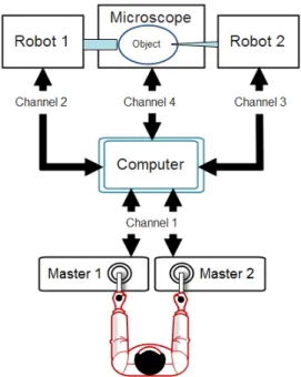
A typical micromanipulation system consists of two master and two slave manipulators with the respective tools attached to them, a microscope, host computer, and often a floating stage with some hardware listed above mounted on it to avoid vibration. Such system is schematically presented in Fig. 1.
Generally, micro-positioning translational stages are used in the capacity of slave manipulators [2, 4,5,6]. These manipulators can provide high accuracy, but it is often excessively high in many cases. In addition, control of a single DOF of a Cartesian stage during injection is not perfectly
suitable for a variety of micromanipulation operations (e.g., biocell injection) since in this case the tool performs lateral injection, as shown in Fig. 2.
Fig. 1. Basic structure of a micromanipulation system
Fig. 2. Cell penetration by lateral (a) and translational (b) motion of the injection needle.
The translational penetration is more beneficial than lateral since it causes less damage to the cell. In order to conduct a translational penetration, an engineer has to make move the needle attached to the XYZ stage in two degrees of freedom (horizontal and vertical) simultaneously, since moving along just one Cartesian axis will provide us with the case (a) depicted in Fig. 2. Having the manipulator capable of positioning the injecting needle along the same inclined line (case (b) in Fig. 2) by controlling just one DOF could simplify injection process and decrease the damage done to the microobject by the end-effector. The relative motion of the needle tip is shown by black arrow in Fig. 2.
Therefore, we decided to design a new mechanism incorporating casual motors and converting rotational motion of their shafts to the translational motion of the end-effector without using any intermediate mechanisms such as precision worm gear. However, even with causal sensors and actuators, we expect the minimum accuracy to be higher than 2 µm. Fig. 3 shows the kinematic structure of new manipulator. The end-effecter of the robot is intended to be attached at point C, while the motors drive the links at points A and E, respectively. The distance between motors is 2∆, all links have equal length
l, α
stands for the angle between initial links and horizontal axis X.Fig. 3. Kinematical structure of the proposed manipulator 2. End-effector Positioning Accuracy
During micromanipulation, we are mostly interested in the motion when the end-effector moves along the horizontal axis. In this case, point C should perform translational motion along X-axis, therefore, the absolute value of the angles between initial links and the X-axis remains equal. Let us denote this angle by
α
. The coordinate of point C therefore can be expressed in terms of α by following equation:2 2
2cos 2 sin
cos + − ∆ −∆
=
l
αl
αl
αX
C (1)Thus, knowing the angular resolution of α and all mechanical parameters, we can estimate the Cartesian positioning resolution of the end-effector.
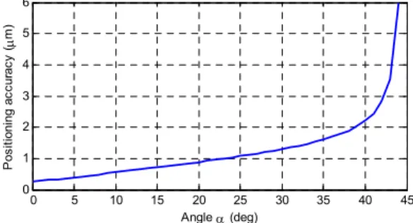
Assuming that motor gear has a gear ratio of 100, encoder has a resolution of 4000 CPT, ∆=15 mm, and l=50 mm, we can calculate and plot the positioning accuracy as afunction of α as follows:
0 5 10 15 20 25 30 35 40 45
0 1 2 3 4 5 6
Angle α (deg) Positioning accuracy (µm)
Fig. 4. Positioning accuracy as a function of angle α As can be seen from Fig. 4, the relation between positioning resolution and α can be treated as linear only if α is less than 35 degrees.
After that, the positioning accuracy decreases abruptly until α reaches the vicinity of 45 degrees.
From that value onward, the solution of (1) contains an imaginary part, which means that for the selected mechanical parameters and angles α manipulator configuration does not exist, and further increasing of α up to 45 degrees will inevitably break the linkages.
It is clear from Fig. 4 that positioning accuracy remains less than the required 2 µm for every α until approximately 38 degrees; maximum value of 35 degrees for α has been chosen, and the hardware has been designed correspondingly. The average accuracy for α = 0°..35° equals 0.814 µm.
3. Hardware Design
Maxon RE 25 DC motors equipped with Maxon MR 1000-CPT encoders and LLC CSF-5-2XH harmonic drives with a gear ratio of 100 have been chosen to be used in the proposed manipulator. Since these encoders have two channels, after quadrupling they provide us with the required 4000 counts-per-turn resolution. The motors were controlled by Maxon 4-Q-DC servoamplifier motor drives. The picture of the manufactured and assembled micromanipulator is presented in Fig. 5.
Fig. 5. Fully assembled manipulator
In Fig. 5, one can notice two motors mounted vertically in parallel with each other (points A and E in Fig. 3), and the links attached to motor gears. There is a third motor capable of changing the slope of the linkage plane; it is placed below protective cover and can be identified by encoder cable on the left. The injecting motion is performed by the couple of vertically mounted motors, and the slope between the linkage plane and microscope table is controlled by the third motor. Therefore, an operator is required to initialize the desired approaching angle in advance, exactly like it is done for all other systems, and he or she can be sure that the approaching itself will be performed without any lateral displacement of the end effector tip which can cause damage to the microobject. This will provide us with safe translational injection exactly like the one shown in Fig. 2, (b).
Ⅲ. Experimental Evaluation The performance of the proposed manipulator has been tested experimentally for two types of controllers: conventional PID-controller and
‘reversible’, or reversed PID-controller [9]. Both of the controllers have been tuned in advance and adjusted during experiments, and the results of their best performances are discussed below. For each controller, two series of experiments – slow velocity and high velocity positioning – have
been conducted. During these experiments, one of the initial links shown on Fig. 3 has been controlled by the corresponding motor while the other one remained still.
1. Positioning under Conventional PID-Controller
During slow velocity experiments, commanded angular displacement α presented a sine wave with the magnitude of 5 encoder counts and angular frequency of 1 rad/sec. The system showed good performance with RMS position error of 0.43437 counts.
0 1 2 3 4 5 6 7 8 9 10
-5 0 5
emax= 2 emin= -1
RMS Error : 0.43437 Desired Angle
Actual Angle
Position (counts)
Time (sec)
Fig. 6. Time plot of low velocity positioning experiments
It is well-known that the performance of every mechanical system can be sufficiently deteriorated by external disturbances, with possibly the most harmful of them being dynamic friction causing stick-slip motion behavior, or stiction [9, 10].
Stiction effects mostly occur when desired velocity changes its sign making the velocity of mechanical system to change its direction either.
In order to show that the proposed manipulator can cope with stiction while providing sufficient accuracy we decided to increase the desired velocity of motion. To assure the safety and good performance of the system, let us say that our system must perform well under the desired velocity of 500 um/sec. The desired signal hence was chosen to be a sine wave with radial frequency of π/2 and magnitude of 500 counts (assuming that 1 encoder count corresponds to 1 µm of end-effector’s translation).
Controller Type RMS Error (counts)
Max/Min Error (counts)
Desired Sine Frequency
(rad/sec)
Casual PID 0.43437 2/-1 1
Reversed PID 0.34367 1/-1
Casual PID 0.83307 2/-2 10
Reversed PID 0.64211 2/-1
Casual PID 1.6662 3/-3 50
Reversed PID 1.2089 2/-3
Controller Type RMS Error (counts)
Max/Min Error (counts)
Worse than Best Performance,
%
Casual P 3.8718 7 /-7 168.29
Casual PI 1.8823 7/-5 30.43
Casual PID 1.4432 4/-4 0.00
Reversed PI 2.4645 7/-5 70.77
Reversed PID 1.7878 4/-5 23.88
0 1 2 3 4 5 6 7 8 9 10
-500 0 500
emax= 4 emin= -4
RMS Error : 1.4432 Desired Angle
Actual Angle Time (sec)
Time (sec) Time (sec)
Position (counts)Position (counts) Position (counts)
1 1.1 1.2 1.3
460 480 500
3 3.1 3.2
-500 -480
(b) -460
(a)
(c)
Fig. 7. Time plot of low velocity positioning experiments The best performance during high velocity experiments shown by the casual PID-controller was with RMS position error of 1.4432 encoder counts.
2. Positioning under Reversible PID-Controller The existence of friction was observed at velocity reversal regions, as can be seen from Fig.
7(b) and Fig. 7(c). It is well-known that the casual PID-controller’s performance may decrease sufficiently in case of the existence of stiction; the reason of such degradation is that integral gain accumulates position error and does not let the system change the sign of the control output (and thus the direction of motion) quickly enough in regions where the desired velocity changes its sign [9]. Therefore, a quite straightforward solution is to manually change the sign of the integral part of PID-controller output in desired velocity sign reversal regions or when the signs of desired and actual velocities are different.
Application of reversible PID-controller let us to decrease positioning error from 0.43437 counts to 0.34367 counts.
0 1 2 3 4 5 6 7 8 9 10
-5 0 5
emax= 1 emin= -1
RMS Error : 0.34367 Desired Angle
Actual Angle
Position (counts)
Time (sec)
Fig. 8. Results of low velocity experiments
However, we were not able to increase the accuracy of micropositioning by applying reversible PID controller during high velocity experiments; in fact, RMS position error was even greater with
reversible (1.7878 counts) comparing to casual PID-controller (1.4432 counts).
The best results for various experiments and controllers are summarized in tables 1-2.
Table 1. Experimental results for low velocity micropositioning with different desired position signal frequencies
Table 2. Experimental results for high velocity micropositioning
We were also able to confirm the accuracy of positioning experimentally basing on visual information obtained from the microscope. The results are presented in Fig. 9. In these experiments, the tip of the end-effecter with the diameter of 120 µm has been positioned by the motion of one motor while the other one remained still. The desired motion law for the motor was a sine wave with the magnitude of 50 counts. In addition, the experiments confirmed that the accuracy of positioning increases with the decrease of angle α, as it follows from (1). The experimental results below are given for α = 20°
(Fig. 9, (a)-(b)) and α = 30° (Fig. 9, (c)-(d)).
Fig. 9. Time plot of low velocity positioning experiments As can be seen from Fig. 9, the end-effecter was positioned along an arc (from upper-left side of the screen toward bottom-right side) as a result of a single motor motion. During the experiments, the designed manipulator was capable of very smooth and accurate positioning of the end-effecter’s tip. According to experimental results, the positioning resolution for the case of α
= 20° was approximately 25 % greater than for α
= 30°, which confirms (1) and Fig. 4.
IⅤ. Conclusion
In this paper, we proposed a novel manipulator for telerobotic micromanipulation. This manipulator has a simple architecture and exhibits high accuracy, which makes it a good alternative to existing micro-positioning stages.
The proposed manipulator has been tested in a series of low and high micro-positioning velocity experiments under two types of controllers and demonstrated good accuracy (roughly 0.34 µm for slow and 1.44 µm for fast positioning). Application of the reversed PID-controller improved the accuracy of low-velocity micro-positioning for all tested frequencies of desired velocity signal; this improvement during all three experimental cases was greater than 25 % compared to the performance shown by casual PID. However, we were not able to increase the accuracy of fast micro-positioning by applying reversed PID.
Further study is required on this issue, along with the development of practical tuning methodology
for the abovementioned controller.
In our future work, we plan to test the proposed manipulator while performing various micromanipulation operations including probing, microassembly, and injection into living cells, and to compare the provided performance with existing analogues. In addition, we are planning to improve the performance of controller and investigate telerobotic system behavior under communication delays between computers while performing micromanipulation from a distant location.
참 고 문 헌
[1] A. Kettler, H. Nasse, W. Geis, V. Wilke, W.
Ansorge, “Method for performing work on cells of a cell culture and apparatus therefor”, U.S.Patent 4 907 158, Mar. 6, 1990.
[2] Y. Sun and B.J. Nelson, “Microrobotic cell injection”, in Proc. of 2001 IEEE Int. Conf.
on Robotics and Automation, pp. 620-625.
[3] P. Kallio and J. Kuncova, “Manipulation of Living Biological Cells: Challenges in Automation,” presented at Workshop on Microrobotics for Biomanipulation at 2003 Int. Conf. on Intelligent Robots and Systems, Las Vegas, USA.
[4] W.H. Wang, X.Y. Liu, Y. Sun,
“Autonomous Zebrafish Embryo Injection Using a Microrobotic System,” in 2007 Proc.
IEEE Int. Conf. on Automation Science and Engineering, pp. 363–368.
[5] H. Huang, S. Dong, J.K. Mills, S.H. Cheng,
“Automatic suspended cell injection under vision and force control biomanipulation”, presented at the 2007 IEEE Int. Conf. on Robotics and Biomimetics, pp. 71–76.
[6] A. Pillarisetti, M. Pekarev, A.D. Brooks, and J.P .Desai, “Evaluating the effect of force feedback in cell injection,” IEEE Trans.
Autom. Sci. Eng., Vol. 4, No. 3, pp. 322-331, 2007.
[7] W. Li and N. Xi, “Novel Micro Gripping, Probing, and Sensing Devices for
Single-Cell Surgery,” in 2004 Proc. of the 26th Int. Conf. of the IEEE EMBS, San Francisco, USA, pp. 2591–2594.
[8] H. Huang, D. Sun, J. K. Mills, and W. J.
Li, “Visual-based Impedance Force Control of Three-dimensional Cell Injection System”, in 2007 Proc. IEEE Int. Conf. on Robotics and Automation, Roma, Italy, pp. 4196–
4201.
[9] J.-H. Ryu, J. Song, D.-S. Kwon, “A nonlinear friction compensation method using adaptive control and its practical application to an in-parallel actuated 6-DOF manipulator”, Control Engineering Practice, vol. 9, pp. 159–167, 2001.
[10] H. Olsson, K. J. Åström, C. C. de Wit, M.
Gafvert, and P. Lischinsky, “Friction models and friction compensation,” Eur. J. Control, vol. 4, no. 3, pp. 176–195, 1998.
가포노브 이고르 (Igor Gaponov)
2006년 5월 : South-West State University, Kursk, Russia(공학 사)
2008년 6월 : 한국기술교육대학 교 대학원 기계공학과(공학석사) 2011년 2월 : 한국기술교육대학 교 대학원 기계공학과(공학박사) 현재 : 한국기술교육대학교 기계정보공학부 전임강 사
<관심분야> Telerobotics, haptics, human-machine interface, micromanipulation.
조 현 찬 (Hyun-Chan Cho) 종신회원
현재 : 한국기술교육대학교 전기 전자통신공학부 교수
<관심분야> 지능시스템, 지능 제어, 로보틱스.