• 검색 결과가 없습니다.

Large Scale Treatment of Perfluorocompounds Using a Thermal Plasma ScrubberSung-Han Han, Hyun-Woo Park, Tae-Hee Kim, and Dong-Wha Park*

N/A
N/A
Protected

Academic year: 2021

Share "Large Scale Treatment of Perfluorocompounds Using a Thermal Plasma ScrubberSung-Han Han, Hyun-Woo Park, Tae-Hee Kim, and Dong-Wha Park*"

Copied!
9
0
0

로드 중.... (전체 텍스트 보기)

전체 글

(1)

* To whom correspondence should be addressed.

E-mail: [email protected] 청정환경기술

Large Scale Treatment of Perfluorocompounds Using a Thermal Plasma Scrubber

Sung-Han Han, Hyun-Woo Park, Tae-Hee Kim, and Dong-Wha Park*

Department of Chemical Engineering and RIC-ETTP (Regional Innovation Center for Environmental Technology of Thermal Plasma), INHA University, 253 Yonghyun-dong, Nam-gu, Incheon, 402-751, Korea

(Received for review June 10, 2011; Accepted August 12, 2011)

Abstract

Thermal plasma has been presented for the decomposition of perfluorocompounds (PFCs) which are extensively used in the semiconductor manufacturing and display industry. We developed pilot-scale equipment to investigate the large scale treatment of PFCs and called it a “thermal plasma scrubber”. PFCs such as CF

4

, C

2

F

6

, SF

6

, and NF

3

used in experiments were diluted with N

2

. There were two different types of experiment setup related to the water spray direction inside the thermal plasma scrubber. The first type was that the water was sprayed directly into the gas outlet located at the exit of the reaction section. The second type was that the water was sprayed on the wall of the quenching section. More effective decomposition took place when the water was sprayed on the quenching section wall. For C

2

F

6

, SF

6

, and NF

3

the maximum destruction and removal efficiency was nearly 100%, and for CF

4

was up to 93%.

Keywords : Thermal plasma, PFCs, C

2

F

6

, CF

4

, SF

6

, NF

3

, Scrubber

1. Introduction

Perfluorocompounds (PFCs) are widely used as etching and cleaning gases in the semiconductor manufacturing and display industry[1-5]. PFCs have an enormous effect on global war- ming because although their emission amount is relatively lower than carbon dioxide (CO

2

), they have high global warming po- tentials (GWPs) which are about several thousands times higher compared to CO

2

[5]. Table 1 shows the lifetimes and GWPs of PFCs[7]. The emissions of perfluorocarbons and sulphur hexafluoride (SF

6

) with high GWPs have been regulated inter- nationally by the Kyoto Protocol and the Bali Roadmap[8-10].

Voluntary efforts to decrease PFCs emissions are now under way in the semiconductor industry. The industry’s activities for the reduction of PFCs can be largely divided into 3 classes.

The first is to replace PFCs with gases which are not regulated by the Kyoto Protocol such as nitrogen trifluoride (NF

3

). The second is to improve the manufacturing process efficiency to reduce the amount of PFCs. The last is to treat the exhausted gases. Treatment of exhaust gases has been considered as a very effective way to abate PFCs directly. Therefore, many studies related to the treatment of these gases have been carried out.

The treatment of PFCs can be achieved via the combustion system[11], catalytic decomposition[12], or by the plasma tech- nique[8,13-17]. In the plasma technique, there are two kinds:

low-temperature plasma processing and high-temperature plasma processing. It is difficult for cold plasma processing to be used practically in industry since large scale treatment of PFCs in our evaluation was found to be unsuitable. Meanwhile, the abate- ment technique using combustion has been attempted, but its decomposition efficiency was evaluated by us to be relatively lower than that of a high-temperature plasma technique. How- ever, it may be expected that the combustion method can be also applied to the large-scale treatment of PFCs. In addition, it seems that for catalytic destruction system to be effective, more investigation is needed before commercialization. There- fore, it may be concluded that among the three methods, hot- plasma processing can be expected to be installed in an actual

Table 1. Atmospheric lifetimes GWP100 of greenhouse gases[6]

Greenhouse gases Atmospheric lifetime (year) GWP100

CO

2

50-200 1

CF

4

50000 6500

C

2

F

6

10000 9200

SF

6

3200 23900

C

3

F

8

2600-7000 7000

CHF

3

250-390 11700

C

4

F

8

3200 8700

CH

4

12 21

N

2

O 120 310

NF

3

50-740 8000

250

(2)

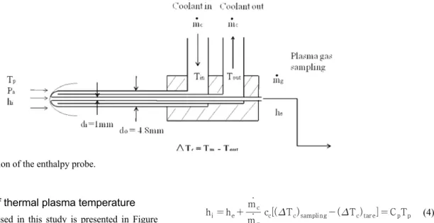
composition using the software program, Factsage [19] was performed and the temperature of the plasma was measured by an enthalpy probe.

2. Experimental 2.1. Decomposition of PFCs

Figure 1 schematically illustrates the experimental setup of the pilot-scale equipment. We developed the pilot-scale equip- ment for the large-scale treatment of PFCs and called it a

“thermal plasma scrubber”. The thermal plasma scrubber was composed of a DC power supply, a torch, a mixing chamber, a reaction section, a quenching section, a water scrubber, and a blower. The anode of the torch was a copper nozzle and the cathode was a tungsten rod. Pure SF

6

, CF

4

, NF

3

, and C

2

F

6

gases were diluted with nitrogen (N

2

) at a mixing chamber, and then those gases were injected into the reaction section through four injection tubes. N

2

was used as the plasma gas, and the flow rates of each PFC and the reactive injection gases including hydrogen (H

2

) and oxygen (O

2

) were controlled by mass flow controllers. The gas flow rate of N

2

was increased from 100 L/min to 300 L/min while the PFCs also increased from 0.5 L/min to 1.5 L/min. When the total treated gas flow rate was 100 L/min, PFCs flow rate was 0.5 L/min. In other words, the

Figure 1. Schematic diagram of the thermal plasma scrubber for removal of PFCs gases.

Figure 2. Schematic diagram of type A and type B.

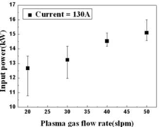
concentration of PFCs was 5,000 ppm. For the water spraying, in order to increase the contact surface area between the gas and the liquid, cylindrical materials were packed inside the water scrubber. The arc current was 130 A, and the power ranged from 12 to 15 kW. Exhausted gases, such as fluorine (F

2

), hydrogen fluoride (HF), nitrogen oxide (NO

x

), and sulfur oxide (SO

x

), were removed through the water scrubber. Table 2 shows the operating conditions in detail.

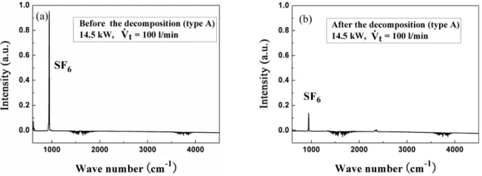
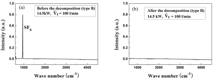
Figure 2 shows the two different types of setup in this study:

type A and type B. In the case of type A, the water was sprayed directly into the gas outlet located at the exit of the reaction section. For type B, the water was sprayed onto the walls of the quenching section to preserve the equipment from the over- heating. The reaction section was 56 mm inside diameter, and the exhausted gases were analyzed by Fourier transform in- frared spectrometer (FT-IR). The destruction and removal effi- ciency (DRE) of PFCs was calculated by Eq (1).

DRE of PFCs    C i

PFCs

C i

PFCs

 C f

PFCs

×  (1)

where, C

iPFCs

is the initial concentration and C

fPFCs

is the final concentration.

Table 2. Operating conditions and parameters for the large treatment Average input power (kW) 12.7-15.1 N

2

plasma gas flow rate (L/min) 20, 30, 40, 50 Total treatment gas flow rate (L/min) 100, 200, 300

Concentration of PFCs (ppm) 5000

Reactive injection gas (H

2

, O

2

) flow rate (L/min) 0.5, 1

(3)

Figure 3. The cross section of the enthalpy probe.

2.2. Measurement of thermal plasma temperature The enthalpy probe used in this study is presented in Figure 3. The inside diameter was 1 mm and the outside diameter was 4.8 mm. It was employed to measure the plasma temperature and was composed of a triple tube. Eq. (2) expresses the energy balance when the probe was not absorbing the plasma gas, which is a tare case. Eq. (3) presents when the probe draws up the plasma gas, which is a sampling case:

m  c c c T ctare   Q plasma (2)

m  c c c T csampling   m g h i  h e    Q plasma (3)

where hi and he are the enthalpies of the plasma gas per unit mass before and after the cooling water cools the gas in the probe, respectively;  m g and  m c represent the mass flow rates of the plasma gas and the cooling water, and △T

c

is the temperature difference of the cooling water. Q plasma is the en- thalpy of the plasma gas per unit time. Cc is the specific heat capacity of the cooling water.

h i  h e   m  g m  c

c c T csampling  T ctare   C p T p (4)

Eq. (4) can be achieved by combining Eq. (2) and (3). C

p

is the specific heat capacity of the plasma gas. Compared to h

i

with high temperature, h

e

can be neglected because the plasma gas is cooled by the cooling water to the room temperature.

Then, the temperature of the plasma (T

p

) can be calculated[20].

3. Results and Discussion 3.1. Thermodynamic consideration

The chemical equilibrium composition for treating PFCs was

calculated by the Factsage software program using the minimi-

zation of Gibbs free energy[19]. Thermodynamic equilibrium

compositions of PFCs as a function of temperature are shown

in Figure 4. It shows that the decomposition of NF

3

starts at

a low temperature region. CF

4

gas, the most difficult compound

to be decomposed among PFCs, needs a temperature above

2,500 K to be decomposed completely. In the case of C

2

F

6

, the

decomposition of C

2

F

6

generates CF

4

. Therefore, for an effec-

(4)

Figure 4. Thermodynamic equilibrium composition of (a) NF

3

, (b) SF

6

, (c) CF

4

, (d) C

2

F

6

.

Figure 5. The radial distribution of the plasma temperature. Figure 6. The axial distribution of the plasma temperature.

tive abatement of C

2

F

6

, all CF

4

gas that was formed should also be treated. In addition, it is expected that harmful F or F

2

with high corrosiveness can be generated when PFCs are decom- posed.

3.2. The measurement of plasma temperature

Figure 5 shows the temperature of the plasma as a function of the radial distance. The measurement point was 20 mm away from the torch nozzle exit. The center line temperature of the plasma was above 6,000 K. It was revealed that the temperature decreases as the radial distance from the center of the plasma increases.

Figure 6 presents the temperature distribution at the center line of the plasma. As the axial distance increased, the plasma temperature was reduced greatly. This demonstrates indirectly the effective length of the plasma. According to the temperature measurement, it was confirmed that the plasma had a tempe-

rature that was high enough to treat PFCs.

3.3. Relation of input power and plasma gas flow rate By changing the plasma gas flow rate and the arc current, the suitable operating condition was achieved. At an applied arc current of 130 A, the plasma was maintained without disconti- nuance even when the plasma gas flow rate was 50 L/min. The voltage was increased by the increase of the plasma gas flow rate, thus causing an increase of the input power. It appeared that the increase of the gas flow rate caused enhanced cooling of the arc plasma resulting in higher impedance. This increases the voltage, thus providing the higher input power.

Figure 7 shows the average input power as a function of the

plasma gas flow rate. The average input power of about 12.7

kW was consumed when the plasma gas flow rate was 20

L/min, and 15.1 kW of power was required for a gas flow rate

of 50 L/min.

(5)

Figure 7. Average input power as a function of the plasma gas flow rate.

3.4. Decomposition of PFCs with type A

Figure 8 shows the destruction and removal efficiency of PFCs, such as CF

4

, C

2

F

6

, SF

6

, and NF

3

, as a function of the average input power when total treatment flow rate (  V t ) was fixed at 100 L/min. Similar to the thermodynamic equilibrium composition, CF

4

is the most difficult gas to decompose and NF

3

is the easiest. As the input power increased, the decom- position efficiency also increased. It was considered that more treatment gases could contact the arc because the arc volume would increase as the plasma gas flow rate increased.

The abatement experiment in the presence of H

2

and O

2

was carried out over the same range of the gas flow rates. Figure 9 presents the destruction and removal efficiency of PFCs as a function of molar ratios of PFCs to H

2

and O

2

. The des- truction and removal efficiency of PFCs is elevated by adding H

2

and O

2

. In case of C

2

F

6

, the destruction and removal effi-

Figure 8. Decomposition of PFCs as a function of the average input power for type A. DRE is the destruction and removal efficiency.

Figure 9. The decomposition of PFCs as a function of H

2

/PFCs, O

2

/ PFCs molar ratio (a) C

2

F

6

, (b) CF

4

, (c) SF

6

for type A.

DRE is the destruction and removal efficiency.

ciencies were enhanced from about 80% to about 98% by injecting H

2

and O

2

. For CF

4

and SF

6

, the destruction and removal efficiencies were slightly increased when H

2

and O

2

were injected. It seems that when H

2

and O

2

were added, the

by-products generated after the treatment might be mainly HF,

CO, CO

2

, SO

2

, etc. Analysis was performed using the ther-

modynamic software program.

(6)

Figure 12. FT-IR analysis of SF

6

. (a) is for before the decomposition and (b) is for after the decomposition (type A).

Figure 10. Decomposition of NF

3

as a function of treatment gas flow rate for type A. DRE is the destruction and removal efficiency.

NF

3

gas was the easiest gas to be decomposed. Therefore, the destruction and removal efficiency of NF

3

was tested over different ranges of gas flow rates. Figure 10 presents the trend of NF

3

decomposition when changing the total treatment gas flow rates and the plasma gas flow rates. The destruction and removal efficiency of NF

3

was increased by increasing the plasma gas flow rate. It appears that high plasma gas flow rate increased the plasma volume, resulting in larger contact volume.

In addition, the destruction and removal efficiency of NF

3

was considerably decreased when the total treatment gas flow rate was increased. It seems that this was due to the reduction of the residence time by increasing the total treatment gas flow rate. Also, it appeared that the plasma temperature would be reduced by introducing more treatment gas because the injected gas was at room temperature. The destruction and removal efficiency of NF

3

reached up to about 100% for about 14.5 kW at a total treatment gas flow rate of 100 L/min, as shown in Figure 10.

Figure 11. Decomposition of PFCs as a function of the average input power for type B. DRE is the destruction and removal efficiency.

3.5. Decomposition of PFCs with type B

Figure 11 shows the trend of destruction and removal effi- ciency of PFCs when changing the average input power. In this case, the total treatment flow rate was 100 L/min and type B was used. As the average input power increased, the destruction and removal efficiency of PFCs was also enhanced. This was probably due to the increase of the plasma volume caused by the increase of the input power. When type B was used, the destruction and removal efficiency of PFCs was enhanced because of the absence of the water spray into the gas outlet, causing a higher temperature at the exit of the reaction section.

When the average input power was 14.5 kW, the destruction and removal efficiency of PFCs had been achieved; up to 93%

for CF

4

, and close to 100% for the other gases.

3.6. Exhaust gas analysis

After decomposing PFCs gases, the exhausted gases were

cleaned by the water scrubber and analyzed by FT-IR. The com-

(7)

Figure 13. FT-IR analysis of SF

6

. (a) is for before the decomposition and (b) is for after the decomposition (type B).

Figure 14. FT-IR analysis of C

2

F

6

. (a) is for before the decomposition and (b) is for after the decomposition (type A).

Figure 15. FT-IR analysis of C

2

F

6

. (a) is for before the decomposition and (b) is for after the decomposition (type B).

position of the exhausted gases from the type A setup was similar to that of the exhausted gases from type B. This result showed that it was not necessary to spray water into the outlet of the reaction section for the removal of hazardous by-products

because the water scrubber did not affect the formation results

of by-products. The water scrubber only cleaned and cooled the

exhausted gas as shown in Figure 12 and Figure 13. Figure 12

presents the FT-IR analysis before and after a SF

6

treatment

(8)

Type A CF

4

0.50 O

2

0.50 52.94

0.50 O

2

1.00 52.41

0.50 H

2

0.50 53.67

0.50 H

2

1.00 51.56

NF

3

0.50 O

2

or H

2

0.00 82.94

SF

6

0.50 O

2

or H

2

0.00 68.57

0.50 O

2

0.50 74.05

0.50 O

2

1.00 73.89

0.50 H

2

0.50 69.65

0.50 H

2

1.00 69.88

Type B

C

2

F

6

0.50 O

2

or H

2

0.00 86.00

CF

4

0.50 O

2

or H

2

0.00 75.72

NF

3

0.50 O

2

or H

2

0.00 94.58

SF

6

0.50 O

2

or H

2

0.00 92.95

* Input power range: 12-16 kW

run for type A while Figure 13 shows that for type B. Toxic gases were not detected. Figure 14 and Figure 15 present the FT-IR analyses of C

2

F

6

for type A and type B, respectively.

When C

2

F

6

was decomposed, CF

4

and CO

2

were detected in the exhaust gas. For other PFCs treatment runs, there were no toxic by-products. However, the exhaust water from the scru- bber had a low pH. Therefore, neutralization equipment was installed.

3.7. Removed amounts of each PFC gas per kWh The removed amounts of each of the four PFC gases per kWh (removed kmoles/kWh) were estimated and are included in Table 3. As expected, for CF

4

the removed amount was the lowest (48.49 removed kmoles/kWh for type A and 75.72 re- moved kmoles/kWh for type B) because of the strong C-F bond and its stable structure. Meanwhile, the amount for NF

3

removed was the highest (82.94 removed kmoles/kWh for type A and 94.58 kmoles/kWh for type B). Addition of oxygen and hydrogen gases slightly increased the removed moles per kWh for type A as presented in Table 3. In all cases the removed moles of each PFC gas per kWh for type B were higher than those for type A. It appeared that the high temperature region

for type B was greater than that for type A, thus causing more treatment of PFCs.

4. Conclusions

The PFC gases diluted with nitrogen were decomposed using the thermal plasma scrubber we developed. The possibility of large scale treatment (100-300 L/min) was tested. Near the cen- ter of the flame the plasma temperature measured by an enthalpy probe was about 6,000K. This shows that the thermal plasma has a high enough temperature for decomposing PFC gases. The destruction and removal efficiency of the type B was greater than that of type A. In case of the type A for a total treatment flow rate of 100 L/min, the maximum destruction and removal efficiencies were 69% for CF

4

, 81% for C

2

F

6

, 95% for SF

6

, and 100% for NF

3

without adding the additive gases (H

2

and O

2

). In this case, the average power used was 15.1 kW. When the same flow rate was treated using type B, the maximum destruction and removal efficiencies achieved were up to 93%

for CF

4

, and close to 100% for the other gases. In this case,

the average power used was 14.5 kW. Destruction and removal

efficiency of PFCs was decreased as the total treatment flow

(9)

rate was increased. In addition, hazardous by-products were cleaned by the water scrubber. From the results of this study, it appears that the thermal plasma scrubber will be a promising apparatus for effective treatment of PFCs.

Acknowledgments

This work was supported by the Regional Innovation Center for Environmental Technology of Thermal Plasma (ETTP) at Inha University designated by MKE (2011).

Reference

1. Chang, J. P., and Coburn, J. W., “Plasma-Surface Interactions,”

J. Vac. Sci. Tech. A, 21(5), 145-151 (2003).

2. Allgood, C. C., “Fluorinated Gases for Semiconductor Manu- facture: Process Advances in Chemical Vapor Deposition Chamber Cleaning,” J. Fluorine Chem., 122, 105-112 (2003).

3. Namose, I., “Optimization of Gas Utiliztion in Plasm Pro- cesses,” IEEE Tran. Semicon. Manufacturing, 16, 429-435 (2003).

4. Tsai, W. T., Chen, H. P., and Hsien, W. Y., “A Review of Uses, Environmental Hazards and Recovery/Recycle Technolo- gies of Perfluorocarbons (PFCs) Emissions from the Semicon- ductor Manufacturing Processes,” J. Loss Prevention Proc.

Ind., 15, 65-75 (2002).

5. Lee, H. J., and Lee, J. H., “Waste Minimization Technology Trends in Semiconductor Industries,” Clean Technology, 4(1), 6-23 (1998).

6. Ravishankara, R., Solomon, S., Turnipseed, A. A., and Warren, R. F., “Atmospheric Lifetimes of Long-Lived Halogenated Species,” Science, 259, 194-199 (1993).

7. Houghton, J. T., Meira Filho, L. G., Callander, B. A., Harris, N., Kattenberg, A., and Maskell, K., “Climate Change 1995- The Science of Climate Change,” Cambridge University Press, New York, 1996, pp. 121.

8. Kim, D.-Y., and Park, D. W., “Decomposition of PFCs by Steam Plasma at Atmospheric Pressure,” Surf. Coat. Tech.,

202, 22-23 (2008).

9. Kyoto Protocol, Climate Change Conference, Kyoto, Japan, Dec. 1-10 (1997).

10. Van Brunt, R. J., and Herron, J. T., “Fundamental Process of SF

6

Decomposition and Oxidation in Glow and Corona Discharge,” IEEE Trans. Electr. Insul., 25, 75-93 (1990).

11. McNabb, J., and Bischke, S., “Optimization of C

2

F

6

Burn Box Destruction,” Semiconductor International, 1(4), 131-134 (1998).

12. Xu, X.-F., Jeon, J. Y., Choi, M. H., Kim, H. Y., Choi, W.

C., and Park, Y. K., “The Modification and Stability of γ- Al

2

O

3

Based Catalysts for Hydrolytic Decomposition of CF

4

,”

J. Mol. Catal. A: Chem., 266, 131-138 (2007).

13. Durme, J. V., Dewulf, J., Leys, C., and Langenhove, H. V.,

“Combining Non-Thermal Plasma with Heterogeneous Cataly- sis in Waste Gas Treatment. A Review,” Appl. Catal. B: En- viron., 78, 324-333 (2008).

14. Radoiu, M. T., “Studies on Atmospheric Plasma Abatement of PFCs,” Radiat. Phys. Chem., 69, 113-120 (2004).

15. Chang, M. B. and Lee, H. M., “Abatement of Perfluoro- carbons with Combined Plasma Catalysis in Atmospheric- Pressure Environment,” Catal. Today, 89, 109-115 (2004).

16. Wang, Y.-F., Wang, L.-C., Shih, M.L., and Tsaic C.-H., “Effects of Experimental Parameters on NF

3

Decomposition Fraction in An Oxygen-Based RF Plasma Environment,” Chemosphere, 57, 1157-1163 (2004).

17. Vartanian, V., Beu, L., and Lii, T., “Plasma Abatement Reduces PFC Emission,” Semiconductor International, 23(6), 191-192 (2000).

18. Han, S.-H., Seon, H. S., Shin, P.-K., and Park, D. W., “Con- version of SF

6

by Thermal Plasma at Atmospheric Pressure,”

Proceeding of ISPC-19, 460 (2009).

19. Factsage, Software Program, Version 5.5, Germany.

20. Rahmane, M., Saucy, G., and Boulos, M. I., “Analysis of The Enthalpy Probe Technique for Thermal Plasma Diagnostics,”

Rev. Sci. Instrum, 66(6), 3424-3431 (1995).

수치

Table 1. Atmospheric lifetimes GWP100 of greenhouse gases[6]
Figure 1 schematically illustrates the experimental setup of  the pilot-scale equipment
Figure 3. The cross section of the enthalpy probe.
Figure 5. The radial distribution of the plasma temperature. Figure 6. The axial distribution of the plasma temperature.
+4

참조

관련 문서

44 글의 첫 번째 문장인 The most important thing in the Boat Race is harmony and teamwork.을 통해 Boat Race에서 가장 중요한 것은 조 화와 팀워크임을

Now that you have the right bike for you, it is important to learn the right riding position.. A poor riding position can lead to injuries

44 글의 첫 번째 문장인 The most important thing in the Boat Race is harmony and teamwork.을 통해 Boat Race에서 가장 중요한 것은 조 화와 팀워크임을

Since every classical or virtual knot is equivalent to the unknot via a sequence of the extended Reidmeister moves together with the forbidden moves, illustrated in Section 2,

웹 표준을 지원하는 플랫폼에서 큰 수정없이 실행 가능함 패키징을 통해 다양한 기기를 위한 앱을 작성할 수 있음 네이티브 앱과

_____ culture appears to be attractive (도시의) to the

- quadriceps tendon 이 슬개골 하연에서 tibial tuberocity에 부착.

In the chapters of Journey of Renewal that describe the Mission Accountability Framework there will be flashbacks to the story of Richmond Corps, showing clearly how