Journal of the Korean Society for Power System Engineering http://dx.doi.org/10.9726/kspse.2015.19.1.019 Vol. 19, No. 1, pp. 19-23, February 2015
5공 압력프로브의 측정에 의한 Gun식 가스버너의 스월유동장 고찰 Investigation of the Swirling Flow Fields of a Gun-Type Gas Burner by the Measurement of a Five-Hole Pressure
Probe
김장권*†․오석형**
Jang-Kweon Kim*†and Seok-Hyung Oh**
(Received 09 June 2014, Revision received 17 October 2014, Accepted 27 October 2014)
Abstract: The swirling flow fields of a gun-type gas burner(GTGB) without a combustion chamber were measured by a straight-type five-hole pressure probe(FHPP) under the cold flow condition. The three kinds of velocity components and the static pressure were calculated by using a non-nulling calibration method covering the velocity reduction performance of the effective flow attack angle of ±80°. As a result, the velocity and static pressure measured by a FHPP comparatively shows the better performance on the swirling flow of a GTGB than those measured by X-probe.
Key Words:Calibration Map, Five-Hole Pressure Probe(FHPP), Gun-Type Gas Burner(GTGB), Non-Nulling Calibration Method, Slit, Swirl Flow, Swirl Vane
*
†
김장권(교신저자) : 군산대학교 동력기계시스템공학과 E-mail : [email protected], Tel : 063-469-1848** 오석형 : 군산대학교 기계공학부
*
†
Jang-Kweon Kim(corresponding author) : Department of Power System Engineering, Kunsan National University.E-mail : [email protected], Tel : 063-469-1848
** Seok-Hyung Oh : School of Mechanical Engineering, Kunsan National University.
1. 서 론
현재 업소용 가스난방기로 널리 사용 중에 있 는 Gun식 가스버너(이하 GTGB라고 함)는 스월 (swirl)유동을 일으키는 대표적인 버너이다. 버너 중심부에는 회전유동을 일으키는 다수의 스월베 인(swirl vane)들이 설치된 배플판(baffle plate)이 있고, 배플판 외주에는 유동축 방향으로 제트(jet) 를 형성시키는 다수의 슬릿(slit)들이 존재한다
1-5).
본 연구에서는 GTGB의 스월유동장을 정확히 측정하고자 3차원 평균속도성분뿐만 아니라 정압 까지도 동시에 얻을 수 있는 5공압력프로브(이하
FHPP라고 함)
6,7)를 사용하였다. 이 FHPP는 레이저 유속계(LDV), 입자영상유속계(PIV) 및 열선풍속계 (HWA)에 비해 저가형이면서 역유동(reverse flow) 이나 재순환유동(recirculation flow) 및 스월이 동 반된 유동장내에서도 널리 사용되고 있다. 그러나 FHPP는 LDV, PIV 및 HWA들과 달리 난류특성치 들을 얻지 못한다는 단점도 있다. 따라서 연구하 고자 하는 목적에 따라 FHPP를 선정하는 것이 좋 을 듯하다.
그동안 GTGB에 대한 연구들
1-5)은 저자들에 의
해 주로 HWA의 X-형 열선센서(이하 X-probe라고
함)를 이용하였다. 따라서 본 연구에서는 GTGB를
FHPP로 측정하는데 있어, 그 실험결과들의 신뢰 성 및 문제점들을 확보하고자 기 발표된 X-probe 측정에 의한 실험결과들과 전산유체역학(이하 CFD라고 함)으로 수치 해석한 결과
8)와도 상호 비 교하고자 한다.
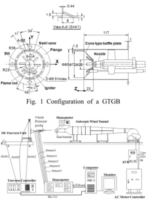
Fig. 1 Configuration of a GTGB
Fig. 2 Data acquisition system using a FHPP
Fig. 3 Data measurement program using a FHPP
2. 실험장치 및 실험방법
2.1 실험장치
Fig. 1은 본 실험에서 사용한 GTGB의 형상 및 제원을 나타낸 그림이다. 이 버너는 난방능력 15,000 kcal/hr의 가스난방기에 적용하고자 개발한 버너이다. 이 GTGB는 중심부 선단에 45°로 경사 진 콘(cone)형 배플판과 배플판 외주에 45° 간격으 로 배치된 8개의 공기분출 슬릿들로 구성되어 있 다. 배플판은 중심에서 직경 25 mm까지는 막혀 있으며, 그 이후 직경 57.8 mm까지는 스월베인 8 개가 45°간격으로 배치되어 있다. 본 연구에서는 화염봉(flame rod)과 점화장치(igniter)를 제거하고, 그 구멍들을 메운 후 실험에 사용하였다.
Fig. 4 Geometry of a straight-type FHPP
Fig. 2는 GTGB의 유동장을 직선형 FHPP로 자 동 측정하기 위해 사용한 데이터 획득 시스템이 다
6). 여기서 아음속풍동은 인버터(inverter)방식으 로 구동되며, 5마력 원심형 송풍기와 확산부, 정 류실, 수축부, 시험부로 각각 구성되어 있다. 또 3 차원 자동이송장치(Dantec 41T50 & 41T75)는 RS-232C로 연결된 컴퓨터(P4, Win-XP)의 제어를 통해 미리 입력된 3차원 좌표들에 FHPP를 자동 이송시키며, 컴퓨터에는 FHPP와 연결된 5대의 압 력계(Furness, FCO332)들로부터 압력을 얻기 위해 Analog/Digital(A/D) 변환카드(Keithley, KPCI-3101) 가 내장되어 있다. 한편, 계측과정 및 속도데이터 연산 등의 모든 과정은 Fig. 3과 같이 Testpoint(Keithley, ver. 4.5)의 소프트웨어를 이용 하여 만들어진 전용 계측프로그램을 사용하였다.
Fig. 4는 본 연구에서 사용한 직선형 FHPP
(United Sensor Corp., USNH-F-172 0346)의 상세
-100 -80 -60 -40 -20 0 20 40 60 80 100 -2
0 2 4 6 8 10 12 14 16
X-probe 5-hole probe RLZ k-
Axial velocity, VZ(m/s)
Radial distance, X(mm) Z=5 mm
Y=0 mm
-100 -80 -60 -40 -20 0 20 40 60 80 100 -2
0 2 4 6 8 10 12 14 16
Z=15mm Y=0mm
Axial velocity, VZ(m/s)
Radial distance, X(mm)
-100 -80 -60 -40 -20 0 20 40 60 80 100 -2
0 2 4 6 8 10 12 14 16
Z=25mm Y=0mm
Axial velocity, VZ(m/s)
Radial distance, X(mm)
-100 -80 -60 -40 -20 0 20 40 60 80 100 -2
0 2 4 6 8 10 12 14 16
Z=35mm Y=0mm
Axial velocity, VZ(m/s)
Radial distance, X(mm)
-100 -80 -60 -40 -20 0 20 40 60 80 100 -2
0 2 4 6 8 10 12 14 16
Z=55mm Y=0mm
Axial velocity, VZ(m/s)
Radial distance, X(mm)
-100 -80 -60 -40 -20 0 20 40 60 80 100 -2
0 2 4 6 8 10 12 14 16
Z=95mm Y=0mm
Axial velocity, VZ(m/s)
Radial distance, X(mm)
-100 -80 -60 -40 -20 0 20 40 60 80 100 -2
0 2 4 6 8 10 12 14 16
Z=125mm Y=0mm
Axial velocity, VZ(m/s)
Radial distance, X(mm)
-100 -80 -60 -40 -20 0 20 40 60 80 100 -2
0 2 4 6 8 10 12 14 16
Z=155mm Y=0mm
Axial velocity, VZ(m/s)
Radial distance, X(mm)
-100 -80 -60 -40 -20 0 20 40 60 80 100 -2
0 2 4 6 8 10 12 14 16
Z=205mm Y=0mm
Axial velocity, VZ(m/s)
Radial distance, X(mm)
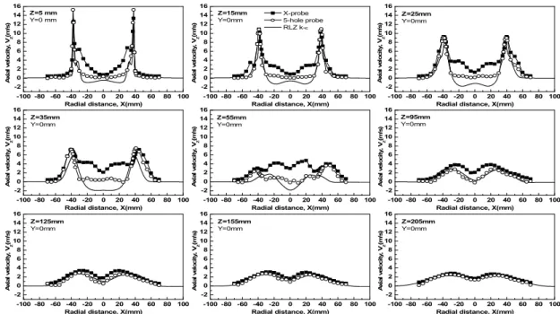
Fig. 6 Axial mean velocity component profiles along the radial distance 제원을 나타낸 그림이다
6,7). 피토관 선단부에는 5
개의 압력측정용 구멍이 형성되어 있는데, 중심부 의 관 직경은 0.508 mm이며, 나머지 4개의 관 직 경은 모두 0.4064 mm이다.
2.2 실험방법
-3.0 -2.5 -2.0 -1.5 -1.0 -0.5 0.0 0.5 1.0 1.5 2.0 2.5 3.0 -3.0
-2.5 -2.0 -1.5 -1.0 -0.5 0.0 0.5 1.0 1.5 2.0 2.5
3.0 -3.0 -2.5 -2.0 -1.5 -1.0 -0.5 0.0 0.5 1.0 1.5 2.0 2.5 3.0
-3.0 -2.5 -2.0 -1.5 -1.0 -0.5 0.0 0.5 1.0 1.5 2.0 2.5 3.0
C
P- P it ch C o ef fi ci ent
C
P- Yaw Coefficient
Straight-Type 5-hole Calibration Map - 16.44m/s(+80)
(-80)
(+80) (-80)
=0
=0
Fig. 5 Calibration maps of a FHPP
Fig. 5는 FHPP로부터 계측된 5개의 압력들을
넌널링(non-nulling)방법으로 속도 및 정압성분들
을 얻기 위해 사용한 교정지도이다. 본 연구에서
는 직선형 FHPP를 사용하면서도 Fig. 5의 교정지
도에서 ±45°에 해당하는 중심부 이외에 4개의 상
한들에 포함한 총 5개의 영역으로 분할한 후, 각
각의 분할영역에 해당하는 교정지도를 3차원커브
피팅(curve-fitting) 프로그램인 TableCurve3D로 근
사함수를 만들어 유효유동각을 ±80°까지 확장시
킬 수 있는 새로운 교정방법
7)을 사용하였다. 또
아음속풍동의 속도는 GTGB의 원통측면에 설치된
압력탭(tap)에서 실제 연소용 공기로 사용되는 공
기량 450 /min을 공급하였을 때, 얻어지는 압력
164 Pa을 기준으로 설정하였다
1-5). 또 압력계들로
부터 압력들을 차례로 읽기 위해 사용한 A/D변환
기의 샘플링(sampling) 주파수는 채널당 10 kHz였
으며, 샘플링 수는 채널당 32,768개였다. 한편, 주
어진 일정한 풍량 조건하에서 Fig. 1의 X-Z평면으
로 FHPP를 이송한 모든 정보들은 기 발표된 실험
결과들
1-5)과 공유하였다.
-120-100 -80 -60 -40 -20 0 20 40 60 80 100 120 -20
-15 -10 -5 0 5 10 15 20 25 30 35
5-hole probe RLZ k-
Static pressure, PS(Pa)
Radial distance, X(mm) Z=5 mm
Y=0 mm
-120-100 -80 -60 -40 -20 0 20 40 60 80 100 120 -20
-15 -10 -5 0 5 10 15 20 25 30 35
Z=15mm Y=0mm
Static pressure, PS(Pa)
Radial distance, X(mm)
-120-100 -80 -60 -40 -20 0 20 40 60 80 100 120 -20
-15 -10 -5 0 5 10 15 20 25 30 35
Z=25mm Y=0mm
Static pressure, PS(Pa)
Radial distance, X(mm)
-120-100 -80 -60 -40 -20 0 20 40 60 80 100 120 -20
-15 -10 -5 0 5 10 15 20 25 30 35
Z=35mm Y=0mm
Static pressure, PS(Pa)
Radial distance, X(mm)
-120-100 -80 -60 -40 -20 0 20 40 60 80 100 120 -20
-15 -10 -5 0 5 10 15 20 25 30 35
Z=55mm Y=0mm
Static pressure, PS(Pa)
Radial distance, X(mm)
-120-100 -80 -60 -40 -20 0 20 40 60 80 100 120 -20
-15 -10 -5 0 5 10 15 20 25 30 35
Z=95mm Y=0mm
Static pressure, PS(Pa)
Radial distance, X(mm)
-120-100 -80 -60 -40 -20 0 20 40 60 80 100 120 -20
-15 -10 -5 0 5 10 15 20 25 30 35
Z=125mm Y=0mm
Static pressure, PS(Pa)
Radial distance, X(mm)
-120-100 -80 -60 -40 -20 0 20 40 60 80 100 120 -20
-15 -10 -5 0 5 10 15 20 25 30 35
Z=155mm Y=0mm
Static pressure, PS(Pa)
Radial distance, X(mm)
-120-100 -80 -60 -40 -20 0 20 40 60 80 100 120 -20
-15 -10 -5 0 5 10 15 20 25 30 35
Z=205mm Y=0mm
Static pressure, PS(Pa)
Radial distance, X(mm)
Fig. 7 Static pressure profiles along the radial distance
3. 실험결과 및 고찰
3.1 평균속도 분포
Fig. 6은 GTGB의 출구로부터 유동축방향으로 9군데의 각 위치에서 반경방향의 거리 증가에 따 라 FHPP에 의해 얻어진 유동축방향속도성분(
) 의 분포를 CFD로 해석한 결과8)와 X-probe를 갖는 열선풍속계로 측정한 결과들
1-5)을 상호 비교한 그 림이다. 여기서 CFD해석결과는 비압축성, 3차원 정상상태에서 realizable(이하 RLZ라고 함) k-ε난 류모델로 해석한 내용이다.
Fig. 6에 나타낸 FHPP에 의한
의 크기 및 분 포형상은 GTGB의 슬릿부 외곽의 경우 X- probe 및 RLZ k-ε의 해석결과와 비교적 잘 일치함을 알 수 있다. 그러나 GTGB 안쪽의 경우 Z=95 mm 이전에서 FHPP에 의한 는 X-probe에 의한 결과 보다 작은 반면, RLZ k-ε의 해석결과보다 큰 크 기를 나타내고 있다. 특히 회전유동의 영향이 강 한 GTGB의 중심부에서 는 음(-)의 값을 나타내 기 때문에 역유동(reverse flow)을 보여주는 것으로 판단되어 Z=95 mm까지는 재순환유동(recirculation
는 음(-)의 값을 나타내 기 때문에 역유동(reverse flow)을 보여주는 것으로 판단되어 Z=95 mm까지는 재순환유동(recirculation
flow)이 존재함을 잘 알 수 있다. 그러나 FHPP에 의한
는 동일 위치에서 음(-)의 크기까지는 보 여주지 못해 역유동이나 재순환유동특성을 정확 히 확인할 수는 없지만, 그래도 X-probe보다는 더 음의 값에 가깝게 보여주므로 FHPP의 성능이 X-probe의 성능보다는 더 우수하다는 것을 알 수 있다. Z=95 mm이후에서는 3가지 의 결과들이 점차 서로 일치해가지만, 특히 FHPP에 의한 결과 가 더 빨리 해석결과와 일치함을 알 수 있다. 한 편, Z=5 mm에서 버너 슬릿부의 FHPP에 의한 값이 X-probe에 의한 결과와 RLZ k-ε의 해석결 과보다 더 크게 나타난 것은 FHPP의 정확한 위치 선정이 되지 않았거나 빠른 속도로 길이가 긴 FHPP의 미소한 흔들림 등이 반영된 실험부정확에 따른 오차로 간주된다.
값이 X-probe에 의한 결과와 RLZ k-ε의 해석결 과보다 더 크게 나타난 것은 FHPP의 정확한 위치 선정이 되지 않았거나 빠른 속도로 길이가 긴 FHPP의 미소한 흔들림 등이 반영된 실험부정확에 따른 오차로 간주된다.
3.2 정압분포
Fig. 7은 GTGB의 출구로부터 유동축방향으로
9군데의 각 위치에서 반경방향의 거리 증가에 따
라 FHPP에 의해 얻어진 정압( )의 분포를 RLZ
k-ε으로 해석한 결과와 비교한 그림이다.
Z=5 mm의 버너 슬릿부에서 FHPP에 의한 정압 측정값도 해석결과보다 더 큰 크기를 보여
의 경우와 같이 오차가 발생한 것으로 보인다. 그러 나 축방향 거리가 증가함에 따라 FHPP에 의한 정 압분포는 대체로 해석결과와 일치해 감을 알 수 있다.
4. 결 론
GTGB의 스월유동장을 FHPP로 측정한 결과 다 음과 같은 결론을 얻을 수 있었다.
(1) 회전유동의 영향이 적은 GTGB의 슬릿부 외곽부에서 FHPP에 의한 축방향속도성분의 분포 는 X-probe 및 RLZ k-ε해석결과와 비교적 잘 일 치함을 알 수 있다.
(2) 회전유동의 영향이 강한 GTGB의 중심부에 서 역유동을 예측하는 FHPP의 성능은 CFD 해석 보다는 다소 떨어지지만, X-probe보다는 더 우수 하다는 것을 알 수 있다.
(3) GTGB의 스월유동장에 대해서도 FHPP로 충 분히 측정 가능함을 알 수 있다.
References