Enhancement of the Corrosion Resistance of CrN Film Deposited by Inductively Coupled Plasma Magnetron Sputtering
Sung-Yong Chun
1and Seong-Jong Kim
2,†1Department of Advanced Materials Science and Engineering, Mokpo National University 1666, Muan, Jeonnam, 58554, Korea
2Division of marine engineering, Mokpo National Maritime University, Mokpo-si, 58628, Korea (Received April 12, 2021; Revised May 25, 2021; Accepted June 07, 2021)
Inductively coupled plasma magnetron sputtering (ICPMS) has the advantage of being able to dramati- cally improve coating properties by increasing the plasma ionization rate and the ion bombardment effect during deposition. Thus, this paper presents the comparative results of CrN films deposited by direct cur- rent magnetron sputtering (dcMS) and ICPMS systems. The structure, microstructure, and mechanical and corrosive properties of the CrN coatings were investigated by X-ray diffractometry, scanning electron microscopy, nanoindentation, and corrosion-resistance measurements. The as-deposited CrN films by ICPMS grew preferentially on a 200 plane compared to dcMS on a 111 plane. As a result, the films depos- ited by ICPMS had a very compact microstructure with high hardness. The nanoindentation hardness reached 19.8 GPa, and 13.5 GPa by dcMS. The corrosion current density of CrN film prepared by ICPMS was about 9.8 × 10⁻⁶ mA/cm2, which was 1/470 of 4.6 × 10⁻³ mA/cm2, the corrosion current density of CrN film prepared by dcMS.
Keywords: Corrosion resistance, CrN, Films, Inductively coupled plasma, Sputtering
1. Introduction
CrN film is widely used in the industrial fields of cutting tools, engine parts, corrosion resistance coating and surface decoration thanks to its excellent high hardness, high toughness, friction resistance and corrosion resistance properties [1-4]. In particular, thanks to its superior chemical resistance, it is expected to be utilized as a coating material for various cutting/machine tools as well as polymer electrolyte fuel cell separators that use a polymer membrane with ion conductivity requiring corrosion resistance and electrical conductivity as an electrolyte [5]. As for the CrN deposition method, while the conventional method of ion plating, hollow cathode discharge, or DC sputtering has been widely used for decades, a deposition method using high ionization plasma such as HiPIMS (High Impulse Plasma Immersion Magnetron Sputtering) or ion beam assisted deposition is attracting attention recently [6-10]. Among these, the magnetron sputtering is most widely used in industrial fields not only because of its excellent reproductivity and
adhesion but also because of its advantage that film can be achieved even at a high deposition rate and low substrate temperature. However, CrN films prepared by the conventional dcMS are still limitedly applied in industrial fields due to its relatively low mechanical hardness, porous columnar microstructure, and low adhesion to the substrate. Accordingly, in the present study, a CrN film was prepared by ICPMS which is expected to greatly improve the physical properties of the film by generating high density plasma. In addition, the same film was prepared by the conventional dcMS and their physical properties were compared. ICPMS has an advantage of being able to dramatically improve the properties of the coating by increasing the plasma ionization rate and the ion bombardment effect through installation of an ICP antenna, between the substrate and a solid material target used as the cathode, for the purpose of generating ICP [11]. In particular, ICPMS generates plasma in general by applying power to a coil-shaped antenna using an RF (Radio Frequency) power source and has advantages that not only energy is easily delivered to the charged particles inside the antenna through the coil-shaped antenna used as an induction element and no
†Corresponding author: [email protected]
Sung-Yong Chun: Professor, Seong-Jong Kim: Professor
DC magnetic field is required to be applied differently from an internal electrode or ECR (Electron Cyclotron Resonance) but also it can be utilized for processing of relatively large object’s plasma [12]. When we look into the cases of the existing studies related to a CrN coating, many of them were the studies where a CrN film was prepared by reactive sputtering or RF sputtering with the N2/Ar gas mixing ratio changed as a main process variable and its mechanical properties such as hardness were announced, and almost no study case was reported where a coating film was prepared by the latest ICPMS that can generate high density plasma and a comparison was carried out paying attention to the its effect on the corrosion resistance and crystal structure of the film [13,14]. Accordingly, in the present study, CrN films were prepared in the same chamber and process conditions using ICPMS and dcMS respectively to compare their physical properties such as crystal structure and corrosion resistance. In addition to the crystal structure of the film, the preferred orientation change, mechanical hardness measurement, and observation of surface and cross section were also carried out. The result of this comparative study is expected to expand the application field of the latest ICPMS deposition process.
2. Experimental Methods
In the present experiment, Si (100) substrates were used for preparation of CrN films and the substrates were cleaned in acetone and ethyl alcohol for 10 minutes respectively using an ultrasonic cleaner to remove impurities from the substrate surface before they are dried and used. In the present experiment, CrN films were prepared by dcMS and ICPMS respectively, when the experiment conditions were maintained using the same coating chamber and process atmosphere to accurately compare the physical properties and obtain the study result. As for the starting raw material, Cr targets with a diameter of 3”, a thickness of 1/4”, and a purity of 99.99%
were used. Ultra-high purity Ar and N₂ gases were used to achieve the atmosphere for the process, the injections of Ar and N2 were fixed at the 20 sccm respectively showing a ratio of 1:1, and the partial pressures of Ar and N2 gases were controlled using a Mass Flow Controller (MFC). The distance between the substrate and the target
was maintained at 60 mm during the deposition and the substrate was rotated at the speed of about 10 rpm for uniform deposition. Air was discharged using a rotary pump and a turbo molecular pump to lower the initial pressure of the chamber down to about 3.0 × 10⁻⁶ torr and the vacuum level was measured using an ion gauge and a baratron gauge. Pre-sputtering was carried out in an Ar atmosphere to clean the targets and the substrates before deposition. Three types of CrN films were prepared by dcMS and ICPMS. The detailed deposition conditions are shown in Table 1. An XRD (Multi-Purpose X-Ray Diffractometer, EMPYREAN, PANalytical) was used to analyze the crystal phases of CrN coating, preferred orientations, etc. and an FE-SEM (Field-Emission Scanning Electron Microscope, S-3500N, Hitachi) were used to observe 2-dimensional microstructures and morphology. In addition, a Nanoindentation Hardness Tester (MTS XP, MTS System Corporation), a precision hardness tester for thin film, was employed to measure the precise mechanical properties of the coating. A Berkovich diamond indenter was used for hardness measurement and the average value obtained through 16 measurements per specimen was used. A three-electrode corrosion cell was configured using Ag/
AgCl saturated KCl for the reference electrode and a 20 mm × 20 mm platinum mesh for counter electrode.
The initial delay time in 3.5% NaCl solution was set to 3,600 s. Polarization after stabilization was performed with a scan rate of 1 mV/s at the open circuit potential (OCP) of -0.25 ~ 1.2 V. Potentiodynamic pola-rization tests were conducted to electrochemically evaluate the corrosion properties of CrN coating and the tests were repetitively conducted at least 3 times respectively in the same conditions to secure reproducibility of the test.
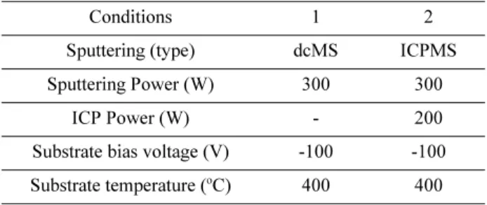
Table 1. Conditions for deposition of CrN films prepared by dcMS, ICPMS
Conditions 1 2
Sputtering (type) dcMS ICPMS Sputtering Power (W) 300 300
ICP Power (W) - 200
Substrate bias voltage (V) -100 -100 Substrate temperature (oC) 400 400
3. Result and Discussion
3.1 Crystal Structure and Orientation
Fig. 1 shows the X-ray diffraction analysis result of the CrN films prepared by the two magnetron sputtering methods, dcMS and ICPMS. The result of the X-ray diffraction analysis shows that all the CrN (pdf 11-0065) films prepared had an FCC (Face-Centered Cubic) structure. In all the CrN films prepared by dcMS, four peaks of (111), (200), (220), and (311) were observed.
But, in the CrN films prepared by ICPMS, (220) and (311) peaks of which the intensities are relatively low were not observed and only two peaks of (111) and (200) were
observed. Meanwhile, it can be seen that the FWHM (Full Width at Half Maximum) of the (200) peak of the film prepared by ICPMS is higher than that of the CrN film prepared by dcMS. When we actually calculate it using the Scherrer equation based on (200) peak, we can see that the average particle size of CrN films prepared by ICPMS was 2.3 nm, replacing 4.3 nm in films prepared by dcMS showing a decrease of about 47 %. In addition, we can see from the result of Fig. 1 that the preferred orientation of CrN film to be obtained also changes greatly depending on the preparation method. It is observed that the preferred orientation in the CrN films prepared by dcMS has changed from (111) facet to (200) facet in the CrN films prepared by ICPMS. A result similar to this trend has been also reported for CrN films prepared by HIPIMS. In general, the orientation of a crystal is closely related to the driving force of the rapid surface energy made up of surface energy and strain energy. Accordingly, it is known that, if strain energy is dominant during CrN growth, the CrN film preferentially grows on (200) facet and, if surface energy is dominant, the CrN film preferentially grows on (111) facet [11]. Accordingly, in the present study, strain energy is expected to have dominantly acted during the growth in the CrN films prepared by ICPMS.
It is thought that the (200) facet 2θ value of CrN film obtained using ICPMS has actually moved to a lower angle from that of the film obtained using dcMS, Fig. 1. XRD patterns of the as-prepared CrN films prepared
by (a) dcMS, (b) ICPMS
Fig. 2. Microstructure through FE-SEM for the CrN film surface [(a) dcMS, (b) ICPMS] and cross-sectional FE-SEM [(c) dcMS, (d) ICPMS]
according to which the residual stress in the film has also increased.
3.2 Microstructure
The microstructural features of CrN film depending on the deposition method were observed using an FE-SEM.
Fig. 2 shows the surficial and cross-sectional photographs.
When the surface photographs of the CrN film are compared first, the films prepared by ICPMS show a particle shape of round granular morphology, small particle sizes, uniform particle size distribution, and dense particle distribution. In the meantime, we can see that the films prepared by dcMS show a particle shape of elongated granular morphology like a rice grain, mixed existence of big and small particles, and existence of many pores. And, when the cross section photographs of the CrN films are compared, although a columnar crystal structure is observed in the films prepared by ICPMS, it is small in size and dense without any defect or pore. On the other hand, it can be observed in the films prepared by dcMS that not only the columnar particles are big in size, loose, and coarse but also obvious interfaces exist between particles. We can presume that, in the case of dcMS where a coating film with a coarse and loose microstructure is obtained in comparison to ICPMS which can obtain a CrN film with a smooth and dense microstructure, the sputter particles which have departed from the target surface for the substrate have failed to receive sufficient energy required to fly/move to the substrate surface to form a film with a dense microstructure.
3.3 Nanoindentation Hardness
Fig. 3 shows the results of measuring the nanoindentation hardness of CrN film prepared by the two methods, dcMS and ICPMS, respectively. As it is not only impossible to measure the hardness of a thin coating having a thickness of several hundred nanometers with a Micro-Vickers Hardness Tester but also difficult to make precise measurements due to the nanoindentation size effect, a Nanoindentation Hardness Tester was used for precise measurement. The nanoindentation hardness of CrN film prepared by dcMS was 13.5 GPa and the nanoindentation hardness of CrN film prepared by ICPMS was 19.8 GPa, which showed that the nanoindentation hardness of CrN film prepared by ICPMS increased almost by 50 % from
that of CrN film prepared by dcMS. The main reasons for the increase in the nanoindentation hardness resulting from the use of ICPMS include a reduction in the average crystal grain size, an increase in the internal stress, and densification of microstructure.
3.4 Corrosion Resistance
To comparatively analyze the effects of the deposition methods on the corrosion resistance of CrN film, a potentiodynamic polarization test that enables the effects to be evaluated with an electrochemical experiment was conducted [15,16]. For more accurate measurement, the conductive silver made line was grounded to the measuring electrode for the potential polarization test. In a specific method, a conductive silver paste was used to connect to the end of the surface of the CrN film, and all Fig. 3. Nanoindentation hardness of CrN films prepared by dcMS, ICPMS
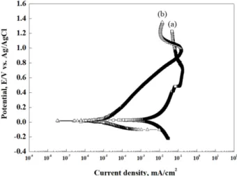
Fig. 4. Potentiodynamic polarization curves of the CrN films prepared by (a) dcMS, (b) ICPMS
parts except for the exposed test surface of the film having an area of 1 cm2 were covered with silicon. Fig. 4 shows the polarization curve for Tafel analysis after the potentiodynamic polarization test. When the effects of the preparation methods on the corrosion potential of CrN film are compared, the corrosion potential of CrN film prepared by dcMS was 0.020 V and the corrosion potential of CrN film prepared by ICPMS was -0.027 V, which showed that the corrosion potential of CrN film prepared by ICPMS was most active. However, when the effects of the preparation methods on the corrosion current density of CrN film are compared, the corrosion current density of CrN film prepared by ICPMS was about 9.8 × 10⁻⁶mA/cm2 which was 1/470 of 4.6 × 10⁻³ mA/cm2, the corrosion current density of CrN film prepared by dcMS.
It means that the corrosion resistance of the coating has been greatly improved. The main reasons why the corrosion current density of CrN film prepared by ICPMS has greatly reduced when compared to that of the film prepared by dcMS also include a reduction in crystal grain size and densification of microstructure. In particular, the corrosion resistance of a CrN film is generally determined by a composite variable such as the surficial and cross- sectional microstructures or average crystal grain size and, as observed in Fig. 2c, pores exist at the crystal interfaces on the surface and cross section of CrN films prepared by dcMS. As NaCl electrolyte permeates through the pores between such crystal boundaries, crystals corrode and the corrosion current density grows bigger to increase the corrosion rate. But, on the contrary, in the microstructure of the film prepared by ICPMS, such micropores and coarse columnar structure disappear, as a result of which the corrosion speed decreases to cause the corrosion current density to go down.
4. Conclusions
In the present study, CrN films were prepared using ICPMS which is expected to greatly improve the physical properties of the film by generating high density plasma, and a comparative study on the crystal structure, microstructure, and mechanical and electrochemical properties was conducted after preparing the same film using dcMS for comparison of physical properties. Though all the CrN films prepared had an FCC structure, four peaks of (111),
(200), (220), and (311) were observed in all the CrN films prepared by dcMS and only two peaks of (111) and (200) were observed in the CrN films prepared by ICPMS. The average particle size of CrN films prepared by ICPMS was 2.3 nm showing a decrease of about 47% when compared to that of the CrN films prepared by dcMS.
When the surface microstructures of CrN film are compared, the films prepared by ICPMS showed a particle shape of round granular morphology, uniform particle size distribution, and dense particle distribution. In the meantime, the films prepared by dcMS showed a particle shape of elongated granular morphology like a rice grain and existence of many pores. As for the nanoindentation hardness, that of dcMS was 13.5 GPa and that of ICPMS was 19.8 GPa, which showed an improvement of about 50 %. As a result of a potentiodynamic polarization test, the corrosion current density of ICPMS was found to have decreased to 9.8 × 10⁻⁶ mA/cm2, which was about 1/470 of 4.6 × 10⁻³mA/cm2, the corrosion current density of dcMS and the corrosion resistance of the film also greatly improved.
References
1. B. Subramanian and M. Jayachandran, Preparation of chro- mium oxynitride and chromium nitride films by DC reactive magnetron sputtering and their material properties, Corro- sion Engineering Science and Technology, 46, 554 (2011).
Doi: https://doi.org/10.1179/147842209X12579401586807 2. Y. Konga, X. Tiana, C. Gonga, and P. K. Chu, Enhance-
ment of toughness and wear resistance by CrN/CrCN multilayered coatings for wood processing, Surface and Coatings Technology, 344, 204 (2018). Doi: https://
doi.org/10.1016/j.surfcoat.2018.03.027
3. P. K. Huang and W. Y. Jien, Effects of nitrogen content on structure and mechanical properties of multi-element (AlCrNbSiTiV)N coating, Surface Coatings and Tech- nology, 203, 1891 (2009). Doi: https://doi.org/10.1016/
j.surfcoat.2009.01.016
4. H. M. Tunga, J. H. Huanga, D. G. Tsai, C. F. Aib, and G.
P. Yua, Hardness and residual stress in nanocrystalline ZrN films: Effect of bias voltage and heat treatment, Materrials Science and Engineering A, 500, 104 (2009).
Doi: https://doi.org/10.1016/j.msea.2008.09.006
5. S. W. Park and S. Y. Chun, A Comparative Study of CrN Coatings Deposited by DC and Pulsed DC Asymmetric
Bipolar Sputtering for a Polymer Electrolyte Membrane Fuel Cell (PEMFC) Metallic Bipolar Plate, Journal of The Korean Ceramic Society, 50, 390 (2013). Doi: https:/
/doi.org/10.4191/kcers.2013.50.6.390
6. X. Guan, Y. Wang, G. Zhang, X. Jiang, L. Wang, and Q.
Xue, Microstructures and properties of Zr/CrN multi- layer coatings fabricatedby multi-arc ion plating, Tribol- ogy International, 106, 78 (2017). Doi: https://doi.org/
10.1016/j.triboint.2016.10.036
7. H. Baránková and L. Bárdos, Comparison of pulsed dc and rf hollow cathode depositions of Cr and CrN films, Surface Coatings and Technology, 205, 4169 (2011).
Doi: https://doi.org/10.1016/j.surfcoat.2011.03.013 8. R. Xingrun, Z. Qinying, H. Zhu, S. Wei, Y. Jiangao, and
C. Hao, Microstructure and Tribological Properties of CrN Films Deposited by Direct Current Magnetron Sputter- ing, Rare Metal Materials and Engineering, 47, 2283 (2018).
Doi: https://doi.org/10.1016/S1875-5372(18)30180-2 9. D. Zhang, X. Zuo, Z. Wang, H. Li, R. Chen, A. Wang, and
P. Ke, Comparative study on protective properties of CrN coatings on the ABS substrate by DCMS and HiPIMS techniques, Surface Coatings and Technology, 394, 125890 (2020). Doi: https://doi.org/10.1016/j.surfcoat.2020.125890 10. S. Kumara, V. S. Rajua, R. Shekhara, J. Arunachalama, A. S. Khannab, and K. G. Prasadc, Compositional char- acterization of CrN films deposited by ion beam-assisted deposition process on stainless steel, Thin Solid Films, 388, 195 (2001). Doi: https://doi.org/10.1016/S0040- 6090(01)00849-5
11. L. Yang, Z. Wang, H. Zhang, Z. Liu, and Q. Chen, The superior properties of CrN coatings prepared by high power pulsed reactive magnetron sputtering, AIP Advances, 10, 015125 (2020). Doi: https://doi.org/10.1063/1.5132783 12. F. Ge, P. Zhu, F. Meng, Q. Xue, and F. Huang, Achieving
Very Low Wear Rates in Binary Transition-Metal Nitrides : The Case of Magnetron Sputtered Dense and Highly Ori- ented VN Coatings, Surface Coatings and Technology, 248, 81 (2014). Doi: https://doi.org/10.1016/j.surfcoat.2014.03.035 13. Y. Tripathi, R. Gupta, Seema, M.l Gupta, D. M. Phaseb, and P. Rajputc, Study of phase formulation in CrN thin films and its response to a minuscule oxygen flow in reactive sputtering process, Thin Solid Films, 670, 113 (2019). Doi: https://doi.org/10.1016/j.tsf.2018.10.009 14. S. Tan, X. Zhang, X. Wu, F. Fang, and J. Jiang, Compar-
ison of chromium nitride coatings deposited by DC and RF magnetron sputtering, Thin Solid Films, 519, 2116 (2011). Doi: https://doi.org/10.1016/j.tsf.2010.10.067 15. K. H. Jung and S. J. Kim, Effect of KCl(s) and K2SO4(s)
on Oxidation Characteristics of the 2.25Cr-1Mo Steel in 10%O2+ 10%CO2 Gas Environment at 650oC, Corro- sion Science and Technology, 19, 43 (2020). Doi: https://
doi.org/10.14773/cst.2020.19.1.43
16. E. S. Kim, H. G. Kim, and H. Jang, Electrochemical Cor- rosion Properties of Amorphous Co-Nb-B Alloys Pre- pared by Melt-Spinning Method, Corrosion Science and Technology, 13, 152 (2014). Doi: https://doi.org/10.14773/
cst.2014.13.4.152
![Fig. 2. Microstructure through FE-SEM for the CrN film surface [(a) dcMS, (b) ICPMS] and cross-sectional FE-SEM [(c) dcMS, (d) ICPMS]](https://thumb-ap.123doks.com/thumbv2/123dokinfo/5403383.217936/3.892.214.681.766.1095/fig-microstructure-sem-surface-icpms-cross-sectional-icpms.webp)