http://dx.doi.org/10.9765/KSCOE.2013.25.3.123
123
Buckling Behaviors of Bucket Foundation for Offshore Wind Tower 해상풍력타워용 버켓기초의 좌굴거동
Gye Hee Lee* and Duc Phu Tran**
이계희*·짠득푸**
Abstract : In this study, the buckling behaviors during the installation of a bucket foundation for an offshore wind turbine tower were investigated. The objective structure was modeled by using a commercial structural analysis
program, and the buckling behavior of the model was estimated as Batdorf's parameter Z in the design code. The surrounding soil conditions and loading condition were applied to the verified analysis model. The effects of parameters such as the longitudinal stiffeners and driven depth were estimated for the buckling capacity. As a result, it was found that the longitudinal stiffeners could drastically increase the buckling capacity in a specific region. In addition, the buckling capacities increased linearly when considering the effect of the surrounding soil.
Keywords : bucket foundation, buckling capacity, Batdorf's parameter, longitudinal stiffener, surrounding soil
요 지 : 본 논문에서는 해상풍력발전터빈의 기초형식 중 하나인 버켓기초의 관입시 발생할 수 있는 좌굴거동에 대 한 연구를 수행하였다. 유한요소를 사용하여 대상구조물을 모델링하고 현재 설계기준의 기본인 원통형 쉘의 좌굴거 동을 해석하여, Batdorf의 계수에 따라 설계기준에 제시된 식과 비교하여 모델의 검증을 수행하였다. 검증된 해석 모델을 바탕으로 인접한 지반의 영향 및 하중조건을 적용하고 종방향보강재와 관입깊이가 좌굴성능에 미치는 영향 을 평가하였다. 평가결과 종방향보강재의 적용은 특정영역에서 좌굴강도를 크게 증가시키고 인접한 지반의 영향은 관입에 따라 선형적으로 증가하는 것으로 나타났다.
핵심용어 : 버켓기초, 좌굴하중, Batdorf 계수, 종방향보강재, 주변지반
1. Introduction
Wind energy is a promising source of energy for the near future, and plans for expanding the capacity in offshore will con- tinue to increase. Various types of foundations have been pro- posed and researched for the construction of offshore wind towers, including gravity-based foundations, monopile founda- tions, jacket foundations, and bucket foundations. Some of the recent research and development projects (Houlsby et al., 2005) have indicated that a bucket foundation (or suction caisson) can be used as an offshore wind turbine foundation under suitable soil conditions. A bucket foundation is installed by using suc- tion as the driving force based on the pressure difference inside and outside the bucket. Lowering the pressure in the cavity causes water flows, which reduce the effective stresses around the tip of the skirt. Hence, the penetration resistance is reduced. There- fore, it does not require heavy installation equipment (Fig. 1).
The shape of a bucket foundation is basically an open shell with a large radius/height ratio. This shape has many advantages for in relation to external loading and its stability (Houlsby et al.,
*목포해양대학교 해양·플랜트건설공학과 (Corresponding author: Gye Hee Lee, Dept of Ocean & Plant Construction Engineering, Mokpo National Maritime University, Mokpo 530-729, Korea. Tel: 061-240-7314, Fax: 061-240-7301, [email protected])
**목포해양대학교 해양·플랜트건설공학과 (Coauthor: Tran Duc Phu, Dept of Ocean & Plant Construction Engineering, Mokpo National Maritime University, Mokpo 530-729, Korea, [email protected])
Fig. 1. Concept of bucket foundation.
2005). However, an opened cylindrical shell can be faced the buckling failure at the installation stage. Especially, this failure would be more severe for a bucket foundation that made in the form of a steel thin- walled steel cylinder, compared to a thick- walled cylinder.
In a previous studies (Pinna et al., 2000; Pinna et al., 2001;
Pinna et al., 2003), these problems were widely researched by using the variational method. In these research were focused on examining the factors influencing the buckling load of for the caisson, including the boundary conditions of the shell, geometric imperfections, material plasticity, embedding ratio, and the amount of lateral restraint offered by the surrounding soil. However, because of the limitations from of the analysis scheme, only unstiffened open cylindrical shells models were considered in the analysis.
In this study, the bucket foundations that have thin-walled cylindrical sections with stiffeners and top caps were mod- eled and analyzed in relation to the buckling behavior. The surrounding soil was also considered in the form of a soil spring. Through the a parametric analysis, factors such as, the shape of cylindrical shell shape, the longitudinal stiff- ener, and the driven depth, the and buckling behaviors of the bucket foundation were estimated.
2. Buckling of Cylindrical Shell
One of the most important papers concerning the buckling of cylinders with a perfect geometry was that by Donnell (1935).
Donnell derived one set of equations based on the assumption that the simplest set of possible relationships is correct.
Batdorf (1947a,b) considered the Donnell equations further, making a comparison between Donnell's results and other the- oretical solutions, where higher order terms were included. A comparison has also been made with experimental data for dif- ferent load conditions. Batdorf's work is also notable because it introduced the non-dimensional parameter Z, which has subse- quently become known as the Batdorf Z parameter. This Z parameter can be more easily explained by using the variational method. By applying the variational method to potential energy expressions, the buckling load can be non-dimensionalized by
(1)
where L is length, a is radius, h is thickness of bucket foundation cylinder (Fig. 2); D is shell bending stiffness,
; E is Young’s modulus, and v is Poisson's ratio;
Pcris the load at buckling or the load at the change of state
from the pre-buckled to buckled state; hydrostatic pressure is used as buckling load.
In addition, according to the Det Norske Veritas (DNV) rec- ommended practice for the buckling strength of shells (DNV- RP-C202, 2010), the buckling load can be calculated as:
(2)
where ρ is coefficient, in case of hydrostatic pressure, ρ = 0.6;
ψ is coefficient, in case of hydrostatic pressure, ψ = 2; ξ is coefficient, in case of hydrostatic pressure, ξ = 1.04 ; Z is Batdorf's parameter, or curvature parameter, .
3. Buckling Analysis System
3.1 Analysis Model
In the analytical models employed in previous studies, the bucket foundations were modeled just simply as thin- walled cylindrical shells. However, in this study, to consider the real shape of a bucket foundations, the thin-walled cylin- drical shell was stiffened by 12 T-shaped longitudinal stiffen- ers, each of which consisted of both a web and a flange. Two types of models were prepared,: the one was modeled for a verification procedure and the other was modeled for a para- metric study. For the parametric study model, the cap of the bucket foundation was also considered. The material of the structures was steel, and its 210 Gpa and 0.3 used as the elas- tic modulus and Poison ratio, respectively.
The confinement effects of the surrounding soil were considered using soil springs that attached to each nodes of the cylindrical shell under the seabed. These springs were connected from the nodes of the shell to the center points of the cylinder. Therefore, the compressive actions of the springs were used to represent the internal constraints of the internal soil constraints, and the tensile actions of the springs were used to represent that of the external soil constraints. For a given driven depth, these springs were recalculated by using soil parameters such as the depth and soil stiffness. The fric- tion and vertical effects of the surrounding soil were ignored.
P∗cr L2a π2D ---Pcr
=
D Eh3
12 1 v( – 2) ---
=
P∗cr ψ 1 ρξ ---ψ
⎝ ⎠⎛ ⎞2 +
=
Z
Z L=ah--- 1 v2 – 2 Fig. 2. Shell parameters (Pinna et al., 2000)
To estimate the buckling capacities of the bucket foundations, a series of buckling analyses was performed using eigen analysis.
Therefore, the dynamic effects of the loading and material proper- ties were not considered. Even though the soil springs could act in a nonlinear manner, only the initial spring constants were used in the analysis because a linear eigen analysis was performed.
3.2 Loads
During the installation phase, two types of loads are applied to a bucket foundation, hydrostatic pressure and self weight. Because the driving force for a bucket foundation is the negative pressure caused by the evacuation of the water inside it, the pressure differ- ence between the inner pressure and external hydrostatic pressure acts as the load. The hydrostatic pressure can simply be given as
(3) where R is hydrostatic pressure; ρ is mass unit of sea water; h is depth of considered point. Because the buckling behaviors corresponding to a longitudinal load are considered, the force obtained by the above pressure multiplied by the area of the cap acts as the main buckling load. The hydrostatic pressures act at the face of the cylinder as a confined pressure.
The boundary conditions play an important role in determin- ing the buckling load of a shell structure. Boundary conditions are present at the lower and upper edges of the cylinder. The lower, open end of the shell generally has either a free or pinned boundary condition. At the beginning of driving, because the cylinder walls are slightly embedded by the self weight, the boundary conditions fall between the free and pinned conditions.
3.3 Analysis Procedure
A numerical parametric study requires many repetitions of the analysis. This is tedious and time consuming. To over- come this inefficiency, all the dimensions of the models were
parameterized; that is, all the dimensions could be changed and analyzed automatically.
This process includes sequence steps. These steps are shown in Fig. 3. ABAQUS(Simulia, 2011), GNU Octave(Eaton, 2007) and python were used as analysis s/w and script, respectively.
4. Analysis Results
The effects of selected parameters on the buckling behav- iors were estimated using the verified buckling analysis system. These parameters were the longitudinal stiffeners and driven depth. In the estimation of these parameters, the effects of the surrounding soil and the cap of the bucket foundation were also considered.
The typical buckling mode shapes are shown in Fig. 4.
The boundary condition for these mode shapes was the pinned-pinned condition. Even for the surrounding soil represented by the spring constraint deformation, the gen- eral deformation characteristic was not changed.
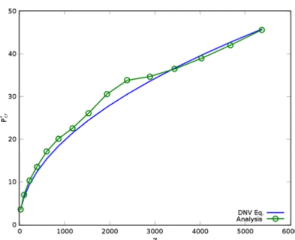
4.1 Verification
To verify the analysis system, relationship of and Bat- dorf's parameter for the unstiffened cylindrical foundation R=ρgh
P∗cr
Fig 3. Analysis procedure.
Fig. 4. Buckling mode shapes.
Fig. 5. Comparison of P∗cr from DNV code and analysis.
was compared with that of the DNV recommendation, as shown in Fig. 5. The used boundary was the pinned-pinned condition. In this figure, the analysis results of this study show good agreements with the code formula driven obtained the analytical method.
4.2 Effects of longitudinal stiffener
To estimate the effects of the longitudinal stiffener at the skirt, three types of T-shaped stiffeners were added longitu- dinally to the unstiffened base model. The dimensions of these stiffeners are listed in Table 1. The bending stiffness of a plate stiffened in a single-directionally stiffened plate can be denoted represented as an orthogonal plate. The Dc and Dl in Table 1 are orthogonal bending stiffness of cir- cumferential and longitudinal direction, respectively.(Chu and Kim, 2002)
The boundary condition models were considered for both the pinned-free and pinned-pinned conditions. In the initial state of the installation, the end of the cylinder is driven into the seabed by its self weight, and the real boundary condition for the bucket foundation would be located between the two con- ditions. It depends on the soil properties of the site.
In Fig. 6, the variations of are shown for pinned-free conditions and pinned-pinned conditions, respectively. The effect of longitudinal stiffeners made the amplification of in whole range of Z. These amplification ranges were focused in Z < 500 and 500 < Z < 1500 for the pinned-free conditions and the pinned-pinned conditions, respectively.
The effects were especially obvious in some Z-value, and both the width of Z and the amplification ratio were much
better in under the pinned-pinned conditions. The Z value of a bucket foundation with normal dimensions (L = 10 m, a = 5 m, h = 0.02 m) was about 900, and this value was located at a highly amplified region of the pinned-pinned conditions.
Because, the stiff soil conditions are closer to the pinned-pinned conditions than those to the pinned-free conditions, the longitu- dinal stiffeners can be a very effective tools for bucket founda- tions that installed at stiff soil sites.
4.3 Driven depth
To estimate the effect of the driven depth on the buck- ling load, a bucket foundation model having a radius of 5 m, length of 12 m, wall thickness of 0.02 m was consid- ered.
In addition, to consider the effect of surrounding soil, the four vertically layered an offshore site condition was assumed. Theses layer properties are listed in Table 2. The properties of soil spring representing these properties were estimated using Malock equation and O'Neil's equaio- ns(KGS,2002) for clay and sand layer, respectively. The spring constants used in model could be obtained by multiply- ing the area of each shell element by the spring coefficients listed in Table 2. The spring coefficients were calculated at the middle of each layer.
As the driven depth increased, the lateral confinement increased. Fig. 7a) shows the change in the buckling load, which was normalized by using the value of the initial state. In this figure, the buckling load capacity increases almost linearly.
Generally, the buckling capacities of structures do not change in the service state. However, in the installation state, this P∗cr
P∗cr
Table 1. Dimensions of stiffener Size (mm)
Dc
(Nm)
Dl
(Nm)
Unstiffened -
1.539E5
1.539E5 Stiffener 1 T200 × 100 × 20 2.775E7 Stiffener 2 T300 × 200 × 20 9,663E7 Stiffener 3 T400 × 300 × 20 2.291E8
Table 2. Properties of soil layers
Type Unitweight (kN/m3)
Thickness (m)
SpringCoeff.
(N/m3)
Layer 1 Clay 7.84E3 4.5 5.30E5
Layer 2 Sand 8.50E3 1.0 1.36E6
Layer 3 Sand 8.50E3 3.0 1.90E6
Layer 4 Sand 8.50E3 1.7 2.25E6
Fig. 7. Relationship of driven depth and buckling load.
Fig. 6. Buckling loads of longitudinal stiffened medel.
increased with the driven depth because the soil constraints increased. Therefore, the additional driving force using auxiliary equipment can be controlled by referring to these results.
With an increase in the driven depth, the new Z value (Z') can be calculated for the upper part not embedded to sea- bed. The curve of dimensionless buckling capacity about Z' is shown in Fig. 7b). This curve is almost constant in the region after Z' = 600. This behavior is different from the previous results that the buckling stiffness was increas- ing with the Z value. This difference is apparently because of the lower boundary condition of this case, because it is closer to a pinned-clamped condition than to a pinned- pinned condition.
5. Conclusion
In this study, the parametric buckling behaviors of a bucket foundation for an offshore wind tower were researched. As a result, it was found that longitudinal stiff- eners could dramatically increase the buckling capacity over a practical range of Z values. In addition, the confine- ment effect of the surrounding soil increased the buckling capacity linearly with the driven depth. However, the curve of dimensionless buckling capacity about modified Z parameter (Z') was different from previous results that increasement as Z value.
These results can be applied to the design and installa- tion process for the maximum efficiency of structures.
감사의 글
본 연구는 국토해양부가 주관하고 한국건설교통기술 평가원이 시행하는 2010 건설기술혁신사업(과제번호: 10 기술혁E04)의 지원을 받아 수행된 연구 결과이며 이에 감 사드립니다.
References
ABAQUS 6.10 User's Manual, Simulia, 2011.
Batdorf, S.B. (1947a). A Simplified Method of Elastic-Stability Analysis for Thin Cylindrical Shells I-Donnell's Equation. Tech.
Not. 1341.
Batdorf, S.B. (1947b). A simplified method of elastic-tability anal- ysis for thin cylindrical shells II-modified equilibrium equation.
Tech. Not. 1342.S
Chu, S.B. and Kim, C.S. (2002). Orthotropic Plate Analysis of Stiffened Plates with Open Ribs, Journal of Korea Society of Steel Construction, 14, 701-711(in Korean)
Donnell, L.H. (1935). Stability of Thin-walled Tubes Under Tor- sion. Tech. Rep. 479, NACA.
Det Norske Veritas (2010). Buckling Strength of Shells, Recom- mended Practice DNV-RP-C202. Det. Nor. Ver. Class. AS, Ver- itasveien 1, N-1322 Hovik, Norway.
Eaton, J.W., Bateman, D. and Hauberg, S (2007), GNU Octave.
Houlsby, G.T., Ibsen, L-B. and Byrne, B.W. (2005) Suction Cais- sons for Wind Turbines. Proc. Int. Symp. Front. in Offsh. Geo- tech., Perth, Australia, pp 75-94.
Korea Geotechnical Sosiety(2002), Deep foundations(in Korean), Koomi Books.
Pinna, R., Martin, C.M. & Ronalds, B.F. (2001). Guidance for Design of Suction Caissons Against Buckling during Installa- tion in Clay Soils. Proc. 11th Int. Offsh. and Pol. Eng. Conf..
Pinna, R. & Ronalds, B.F. (2000). Hydrostatic Buckling of Shells with Various Boundary Conditions. J. of Constr. St. Res., 56, 1- 16.
Pinna, R. & Ronalds, B.F. (2003). Buckling and Postbuckling of Cylindrical Shells with One End Pinned and the Other End Free. Thin-Walled Struct., 41 (6), 507-527.
원고접수일: 2013년 1월 29일 수정본채택: 2013년 4월 26일(1차) 2013년 5월 6일(2차) 게재확정일: 2013년 5월 21일 P∗cr
P∗cr