반도체디스플레이기술학회지 제18권 제4호(2019년 12월)
Journal of the Semiconductor & Display Technology, Vol. 18, No. 4. December 2019.
A Study on Dispersion Behaviors of Fume Particles in Laser Cutting Process of Optical Plastic Thin Films
Kyoungjin Kim
*†*†
Department of Mechanical System Engineering, Kumoh National Institute of Technology
ABSTRACT
The optoelectronic display units such as TFT-LCD or OLED require many thin optical plastic films and their mass manufacturing processes employ CO2 laser cutting of those thin films in a large quantity. However, laser film cutting could generate fume particles through melt shearing, vaporization, and chemical degradation and those particles could be of great concern for film surface contamination. In order to appreciate the fume particle dispersion behaviors in laser film cutting, this study relies on random particle simulations by probabilistic distributions of particle size, ejection velocity and angles coupled with Basset-Boussinesq-Oseen model of particle trajectory in low Reynolds number flows. Here, up to one million particles of random sampling have been tested to effectively show fume particles dispersed on the film surface. The computational results could show that particular range of fume particle size could easily disperse into the pixel region of processed optical films.
Key Words : Electronics Display, Optical Plastic Film, Laser Cutting, Fume Particles, Numerical Simulation
1. Introduction
1In recent advances of electronics display fabrication technologies, many types of optical plastic thin films have been widely utilized in manufacturing of various optoel- ectronic devices such as thin-film transistor-driven active matrix liquid crystal display devices (TFT-LCD) or active matrix organic light-emitting display devices (AMOLED) as well as latest flexible mobile displays [1,2]. These specialized plastic thin films are made of wide ranges of polymeric materials (PET, PC, PMMA, PEN, PAR, PES, PEEK, PI, etc.) [3].
As they possess so many desirable technical qualities that include optical clarity, thermal stability, chemical resistance, dielectric feature, and mechanical strength against scratching and bending, multilayer structures of electronics display are composed of several different optical plastic films. For example, typical LCD mobile displays use PC or PET films
†
E-mail: [email protected]
in polarizer, PMMA in backlight unit, PI films in liquid crystal layer, and many more types of polymer films in various parts.
For this reason, mass manufacturing of LCD and OLED displays requires an efficient cutting process of large sized optical plastic film sheets into pre-determined dimensions.
The plastic film cutting usually employs CO
2laser cutting on highly automated film sheet moving systems. The CO
2laser cutting provides high speed and high precision operations with many advantages of narrow cut width, smooth and flat edges, and relatively small deformation of workpiece [4].
When high powered laser beam interacts with plastic
polymer films, contactless film cutting occurs through
vaporization, melt shearing, and chemical degradation of
plastic films and the process generates fumes in the form of
gas and soot residues [5]. The undesirable fumes are
evidently harmful to human health, so it requires a proper
ventilation along with laser cutting system [6]. The other
concerns regarding laser cutting of polymer films involve the
soot particles, molten droplets, and debris from high speed
A Study on Dispersion Behaviors of Fume Particles in Laser Cutting Process of Optical Plastic Thin Films 63
cutting, as those contamination particles land on the workpiece film and adhere to film surface. If film cut suffers such particle contamination to a high degree, it may degrade the film quality which is obviously unfit for use in display unit fabrication.
The film surface contamination in laser film cutting becomes more severe with increasing cutting speed and it could significantly restrict the cutting quantity and process productivity. Thus, it is important to understand and predict the contamination particle behaviors in laser cutting process of optical plastic films in order to effectively remove or alleviate such problems. This paper introduces the theoretical model of particle ejection and dispersion from laser cut onto the film surface and aims to investigate the general particle dispersion behaviors in terms of film surface contamination.
2. Fume Particle Dispersion Model
In a typical CO
2laser cutting process of optical plastic films for electronics display fabrication, the workpiece plastic films usually have a multilayered structure of dif- ferent polymer materials with optically clear adhesives between the thin multiple film layers. The adhesive layer could become another source of fume particles in addition to soot, debris, and re-solidified molten pool particles from polymer film layers during the laser film cutting [7]. This study assumes that these fume particles are spherical, although their shapes could vary.
As illustrated in Fig. 1, the fume particles generated from laser film cut of optical plastic films and adhesive layer may eject both into vertical directions up and down, but the fume particles ejected upward will be more problematic and become a matter of concern for film surface contamination, once they land on film surface. Assuming that the surround- ing air is quiescent, transient trajectory of fume particles (spherical shape of diameter d
p) can be described as the following simplified form of Basset-Boussinesq-Oseen equation [8].
(1)
(2)
Fig. 1. Schematic of optical plastic film cutting and fume particle generation in CO
2laser cut system.
where r(t) and v(t) are the transient location and velocity vectors of fume particle in a space over the film surface, respectively, and the vector g represents gravitation. In those equations, ρ
sand ρ
fare the mass densities of fume particle and surrounding air, respectively, while μ
fis dynamic viscosity of air. Here, last term of Basset force is ignored due negligible unsteady effect on surrounding air by fume particle movement.
The drag coefficient C
don a spherical particle moving in a fluid is usually given as theoretical or semi-empirical functions of Reynolds number (Re
d= ρ
f|v| d
p/ μ
f), depending on flow types around particles. In Stokes flow regime, we have a simple theoretical relationship of C
d= 24/Re
d, which is only valid for the narrow range of Re
d< 0.1.
For a low Reynolds number flow up to Re
d< 1,000, the following equation should be suitable for assessing viscous drag force on the fume particle dispersion in present case of laser cutting [9].
(3)
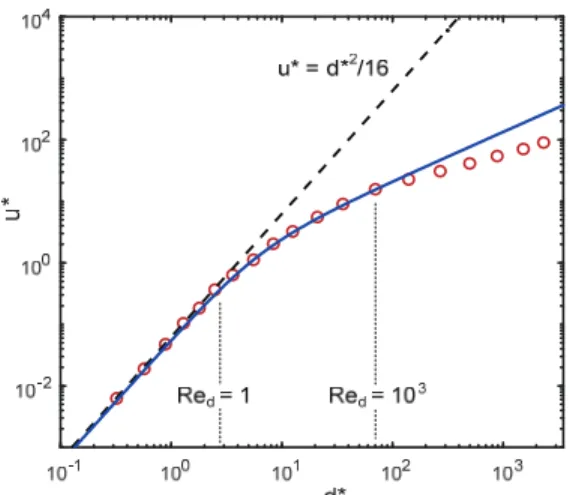
In order to validate the numerical simulation model of fume particle trajectory with above viscous drag correlation, terminal velocity (u
t) of settling particles with varying particle diameter has been evaluated, and the results are shown in Fig. 2 along with measured data [9]. In the figure, u
*and d
*are normalized settling velocity and particle diameter by
(4)
r v dt d
t f f p f
s p
f d p f
s p
t d d d d
d
d C dt d d
g v
v v v
2 3
2 3
2 ) 3 6 (
) 8 ( 2
6
) Re 158 . 0 1 Re (
24
2/3d d
C
d
3 / 2 1
*
)
(
f s f
f
t
g
u
u
Kyoungjin Kim 64
Fig. 2. Validation of viscous drag model for spherical particles. Solid line represents present drag model and dotted line is for model of C
d= 24/Re
d, while symbols are measurements.
(5)
If Stokes flow is assumed, terminal velocity can be simply expressed as u
*= d
*2/16 in a normalized form but it is only valid at significantly small Reynolds number (Re
d<< 1). In contrast, by adopting viscous drag model of Eq. (3) in present analysis, predicted settling velocity is found to match very well with measurements close to the range of d
*< 100 or Re
d< 1,000.
3. Results and Discussion
The present study numerically investigates dispersion behaviors of fume particle from laser film cutting onto the optical film surface under the assumption of spherical shape of fume particles. In order to minimize the particle contamination on processed films, an efficient use of particle suction is required. Still, this study first aims to understand fundamental characteristics of fume particle dispersion in the environment of quiescent air.
In such a case, transient trajectories of fume particles can be predicted by aforementioned dynamic motion model of fume particles ejected from a laser cutting line by solving Eqs. (1) and (2) along with viscous drag relation of Eq. (3).
The difficulty here would be that the initial ejection velocity
Fig. 3. Probability distributions of random ejection velocity (a) and angle (b) for fume particles.
and angle for fume particles should be known as well as the size distribution of fume particles. Such data might be quite difficult to measure through experiments and so far not well documented.
This study has adopted random nature in fume particle generation in laser cutting process. We first assume the probability distributions of particle ejection velocity (lognormal distribution with mean of 1 m/s and variance of 1 m
2/s
2) and particle ejection angles (normal distribution with mean of 0 degree and standard deviation of 25 degrees) from a laser cutting line based on a few previous experimental tests of laser materials processing [10,11], as shown in Fig. 3.
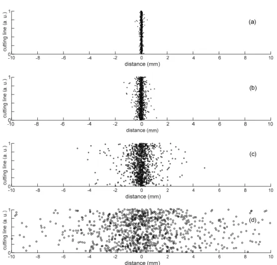
In Fig. 4, the effects of different particle diameters (5, 10, 20, and 50 µm) on particle dispersion have been investigated by testing 1,000 particles in each case with random sampling of ejection velocity and angle at laser cutting line. The circles represent the landing locations of respective fume particles on film surface. Note that vertical line for distance of 0 is meant to be laser cutting line. In case of fume particles with smaller diameters (5 or 10 µm), particles rarely disperse far beyond ±0.5 mm from laser cutting line. If particle diameter is 20 µm, the particle dispersion could reach over ±1 mm from laser cutting line in Fig. 4(c). However, if fume particles could be as large as 50 µm in Fig. 4(d), dispersion distance becomes significantly wide and particles could easily reach over ±5 to 10 mm.
3 / 1 2
*
( )
f f s f p
d g
d
A Study on Dispersion Behaviors of Fume Particles in Laser Cutting Process of Optical Plastic Thin Films 65
Fig. 4. Particle dispersion on film surface near laser cutting line for the simulation of 1,000 particles of randomly assigned ejection velocity and angle. Fume particles of different particle diameters are tested for the cases of (a) d
p= 5 µm, (b) d
p= 10 µm, (c) d
p= 20 µm, and (d) d
p= 50 µm.
In laser cutting of plastic films for mobile display units, there exists allowable margin from cutting lines, as illustrated in Figs. 1 and 5. Film surface contamination by fume particles over this allowable margin become a source of problems, since fume particles could cover the pixels. While the allowable margin could vary, three target margins of ±0.5,
±1.5, ±3 mm are assigned here.
Fig. 6 represents the number fraction of fume particles dispersed outside target margin from laser cutting line, as it is evaluated depending on particle diameter up to 500 µm for each target margin value. Firstly, the particles smaller than 10 µm size mostly stay within target margin near cutting line.
As the fume particles become larger, number fraction over target margin significantly increases. Interestingly, however,
the fume particles large enough to be over 100 µm size or so, this number fraction does not change much and stays quite constant with further increasing particle size.
At this time, dispersion simulation of fume particles over film surface employs the random sampling of fume particle size in addition to previous and identical random assignment of particle ejection velocity and angle from cutting line.
Probabilistic distribution of particle diameter for random sampling is based on lognormal distribution with mean of 10 µm and variance of 200 µm
2, which is depicted as left probability curves (in blue) in each figure of Fig. 7.
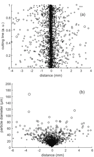
Fig. 8(a) shows the landing locations of 5,000 fume
particles over film surface along the arbitrary cutting line as a
result of random fume particle dispersion simulation using
Kyoungjin Kim 66
Fig. 5. Illustration of laser film cut and target margin in optical plastic film cutting process.
Fig. 6. Effects of particle diameter on number fraction of fume particles dispersed out of target margin.
the aforementioned random sampling models of particle size, particle ejection velocity and angle. Note that the size of circles in Fig. 8 is proportional to diameter of corresponding fume particles. It shows general trends that most of smaller particles stay near the laser cutting line, while larger particles disperse farther from the cutting line.
The identical random particle simulation result is now sorted into the particle diameter in Fig. 8(b) in order to appreciate the effects of particle size on dispersion behavior on film surface. It finds that fume particles of diameter approximately ranging 30 to 60 µm are most frequently observed outside target margin and it agrees with experimental observations in high speed laser film cutting process of mobile display manufacturing.
Back in Fig. 7, right curves (in brown) represent the particle size distribution for only the fume particles dispersed outside target margin. One million particles are randomly
Fig. 7. Particle size distributions of initial fume particle generation (left) and particles dispersed out of target margin (right) for a given target margin.
generated and simulated for the results in this figure. In all three cases for different widths of target margin (±0.5, ±1.5,
±3 mm), particle size distributions of dispersed particles
outside target margin are still very much of lognormal
distribution. The number fractions of particles spread outside
target margin are 4.9, 1.9, and 0.9 percent for each target
A Study on Dispersion Behaviors of Fume Particles in Laser Cutting Process of Optical Plastic Thin Films 67
Fig. 8. Particle dispersion on film surface near laser cutting line for 5,000 particles of randomly assigned ejection velocity and angle (a) and the results are sorted into particle diameter (b). Fume particle diameters are randomly generated based on lognormal probability distribution.
margin width. Once again, considering the original form of particle size distribution (left curves), particle distributions of dispersed particles into the pixel region show the most problematic particle size ranges of 30 to 60 µm. Further research may require the effects of particle suction flows around the laser cutting of plastic films to improve the cut quality of processed films.
4. Conclusions
Present numerical study investigates fume particle dis- persion on the film surface from laser cutting lines in elec-
tronics display manufacturing. The random particle simu- lations of ejected fume particles of varying diameter in the quiescent air have been carried out by applying the probabilistic distribution models. The computational results give the dispersion behaviors of randomly ejected fume particles outside allowable target margin of laser cutting. A random simulation of one million particles confirms that the fume particles of size ranging 30 to 60 µm are primary concerns of film surface contamination.
Acknowledgment
This paper was supported by Research Fund from Kumoh National Institute of Technology.
References
1. MacDonald, W. A., “Engineered Films for Display Technologies,” Journal of Materials Chemistry, Vol. 14, pp. 4-10, 2004.
2. Ohshima, H., “Mobile Display Technologies: Past Developments, Present Technologies, and Future Opportunities,” Japanese Journal of Applied Physics, Vol. 53, pp. 03CA01-1-9, 2014.
3. Ni, H.-J., Liu, J.-G., Wang, Z.-H., and Yang, S.-Y., “A Review on Colorless and Optically Transparent Polyimide Films Chemistry, Process and Engineering Applications,” Journal of Industrial and Engineering Chemistry, Vol. 28, pp. 16-27, 2015.
4. Dubey, A. K. and Yadava, V., “Laser Beam Machining,”
International Journal of Machine Tools and Manufacture, Vol. 48, pp. 609-628, 2008.
5. Powell, J., CO
2Laser Cutting, 2nd Ed., Springer-Verlag:
London, 1998.
6. Chan, Y.-J., Yuan, T.-H., Sun, H.-C., and Lin, T.-C.,
“Characterization and Exposure Assessment of Odor Emissions from Laser Cutting of Plastics in the Optical Film Industry”, Aerosol and Air Quality Research, Vol.
16, pp. 2216-2226, 2016.
7. Woo, C. H., “Research Trend of OCA for Display Panel by Analysis of Patent and Papers Publication,” Journal of the Semiconductor and Display Technology, Vol. 17, pp. 75-84, 2018.
8. Friedlander, S. K., Smoke, Dust, and Haze, 2nd Ed., Oxford University Press: New York, 2000.
9. Brown, P. B. and Lawler, D. F., “Sphere Drag and Settling Velocity Revisited,” Journal of Environmental
-4 -3 -2 -1 0 1 2 3 4
distance (mm) 0
0.2 0.4 0.6 0.8 1
(a)
-6 -4 -2 0 2 4 6
distance (mm) 0
20 40 60 80 100 120 140 160 180 200
(b)
Kyoungjin Kim 68