저작자표시-비영리-변경금지 2.0 대한민국 이용자는 아래의 조건을 따르는 경우에 한하여 자유롭게 l 이 저작물을 복제, 배포, 전송, 전시, 공연 및 방송할 수 있습니다. 다음과 같은 조건을 따라야 합니다: l 귀하는, 이 저작물의 재이용이나 배포의 경우, 이 저작물에 적용된 이용허락조건 을 명확하게 나타내어야 합니다. l 저작권자로부터 별도의 허가를 받으면 이러한 조건들은 적용되지 않습니다. 저작권법에 따른 이용자의 권리는 위의 내용에 의하여 영향을 받지 않습니다. 이것은 이용허락규약(Legal Code)을 이해하기 쉽게 요약한 것입니다. Disclaimer 저작자표시. 귀하는 원저작자를 표시하여야 합니다. 비영리. 귀하는 이 저작물을 영리 목적으로 이용할 수 없습니다. 변경금지. 귀하는 이 저작물을 개작, 변형 또는 가공할 수 없습니다.
Nomenclature
A AR α ' α B c CL CD CDs CLs CL/CD CP CT Cμ Cq D d dD dL dQ dT Ft FX FY hg : : : : : : : : : : : : : : : : : : : : : : : : : Swept area Aspect ratioAxial flow induction factor Tangential flow induction factor Number of blade
Chord length Lift coefficient Drag coefficient
Drag coefficient for αs
Lift coefficient for αs
Lift to drag ratio Power coefficient Thrust coefficient
Turbulence modeling constant torque coefficient
Drag force
Camber thickness Local drag force Local lift force Local torque Local thrust
Prandtl's correction factor Horizontal force
Vertical force Averaged height
h' h0 k L N P Pe PW P0 , P1 P2 , P3 Q R r S T u u1 VC VF VR VD V0 V' W Z0 : : : : : : : : : : : : : : : : : : : : : : : : : Measurement height Extrapolation height Turbulence kinetic energy Lift force
Rotational speed Power
Nominal power Power from wind Atmospheric pressure
Front and rear pressure of swept area Torque Radius Local radius Wing area Thrust Axial velocity Outlet velocity Cut in wind velocity Cut out wind velocity Rated wind velocity Design wind velocity Free stream velocity
Measurement wind velocity Relative velocity
Greek letters α αs , ε ω β ηg ηm θ T μ ρ σr ψ τ Ω ω : : : : : : : : : : : : : : : : Angle of attack
Angle of attack when stall occurs Dissipation rate (chapter 2)
Inclination of local blade chord
Efficiency of power train and generator Mechanical efficiency
Pitch angle
Tip Speed Ratio (TSR) Local Tip Speed Ratio
Non-dimensional local position, Viscosity Air-density, water-density
Local solidity Flow angle Stress tensor Angular velocity
20 , , , , . 20 . Fig. 1.1 IEC2010 2007 2035∼ 49% 2007 4954 , 2020 5904 , 2035 7394 .[1]
Holdren(1990) 21 2060 2 . , 21 , , , . 96.7% . , , , . . . , . ,
. (NASA) 100 kW 2003 40 GW . . , . , . , . 21 . Fig. 1.2 2000 17,400 MW 2007 93,864 MW 5 (76,464 MW) . 3 2005 11,531 MW 2006 15,245 MW, 2007 19,865 MW .
, 20 , CFD , Ansorge Phoenix , . , . . Sorensen[2] k-ω
vortex resolution , Wobou[3]
Fluent LES near wake
. Alinot Masson[4] atmospheric boundary layer
flat terrain , .
Somers[5] NREL S809
, Walter[6] Somers (transition
point) CFD . Brodeur[7]
CFD Mayda[8] CFD
Fluent
.
. Nilay[10] yaw
LES(Large Eddy Simulation) , Sorensen[11]
k-ω . Lindengurg[12]
. . . . 840 .
Lunar Energy(Fig. 1.3(a)),
MCT(Fig. 1.3(b)), EB
.
Blue Energy Canada Canoe Pass, Tidal Electric
.[14][15] Fig. 1.4
, 5.5 m/s . 2~3 m/s . 2009 5 1 MW , 2013 9 kW . .
N 평양 서울 대전 광주 부산 대구 시화 호(252천kW ) 인 천만(72만kW) 가로림만 (48만 kW) 천수만(60만kW ) 울돌목 장죽수도 흑산도 맹골수도 : 조력발전 후보 지 : 조류발전 후보 지 : 파력발전 후보 지 제주도 울릉도 영 일만 대방 수도
. 50% , 1 . , , , , , , , . , , , , .
CFD(computational fluid dynamics) .
(blade element theory) ,
, .
HAWT(horizontal Axis wind turbine) 3 , HAWT 3 . HAWT , HAWT . CFD .
. , , . , , .[17] . . . . . .[18] .
, . 1,000m , . 15m , 40m . (2.1) . α (2.1) : 실측높이의 풍속 : 측정된 높이에서의 풍속 : 실측높이 : 측정높이 α : 표면거칠기에 의존하는 인자 α 0.143(1/7) , .
(modified power law model) . α (2.2) (2.3) (2.4) , (m) . , , , . (2.3) , (roughness length, m) . , .
, .
(2.1)~(2.4)
, Table 2.1 , Table 2.2
Roughness Class
Roughness
Length m Landscape Type
0.321~0.92 0.001~0.02
Smooth (Sea level, Sand,
Snow) 0.92~3 0.02~0.3 Rather rough (Grass, Suburbs) 3 4.5~ 0.3~2 Rough (Residential street) 4.5 6~ 2 10~ Very rough (City)
Jan. Feb. Mar. Apr. May. June July Aug. Sep. Oct. Nov. Dec.
15m 3.3 2.9 3.1 3.0 2.7 2.6 3.2 2.7 3.4 2.6 2.8 3.0
30m 4.8 4.2 4.5 4.4 4.0 3.8 4.6 4.0 4.9 3.8 4.1 4.4
40m 5.1 4.6 4.9 4.7 4.3 4.2 5.0 4.3 5.3 4.2 4.4 4.7
,
.
Weibull [Percival and Harper, 1982],
Rayleigh [Brode, et al., 1980], Beta [Vankuiken, et al.,
1980], Exponential Rayleigh
Weibull , Weibull
.
Weibull (Probability density function), P(V)
. (2.5) C Scale parameter K Shape parameter . (2.6) . ∙ ∙ ∙ ∙ ∙ (2.6)
, : 동력계수 : 로터 블레이드의 회전력을 전달하는 동력장치의 효율 : 발전기의 효율 (2.6) V3 3 . Weibull P(V) (2.7) . (2.7)
∞ (2.8) . (2.9) Γ Γ (2.10)(2.9) (2.10) , Γ Γ (2.11) Γ , , . Γ Γ ≠ ․․․․․
(cummulative distribution function),
.
(2.12)
(2.12)
. (2.13) ln (2.14) (2.14) . , , , , (least square method) . . Matlab(v6.1) .
ρ ρ Γ ρ η η
∞ η η
ρ η η
평균에너지량 정격출력
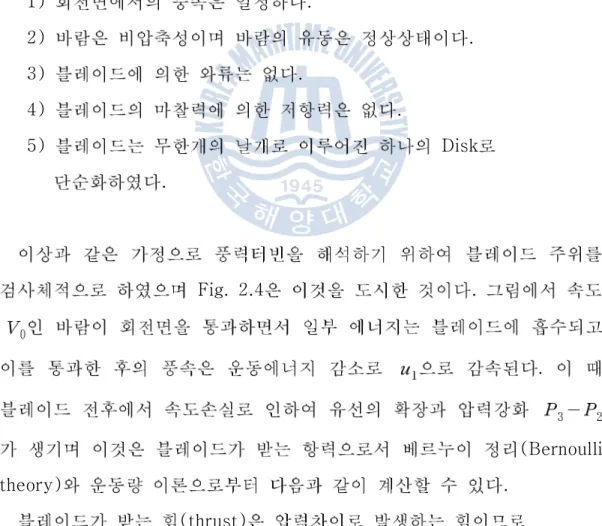
Fig. 2.4 . Disk . . 1) . 2) . 3) . 4) . 5) Disk . Fig. 2.4 . . (Bernoulli theory) . (thrust)
(2.25) . Disk ρ ρ (2.26) ρ ρ (2.27) . . ρ (2.28) (disk) ρ (2.29)
. Fig. 2.4 Stream tube
ρ (2.30) (2.29) (2.30) (2.31) . . (2.32) (2.33) . ( ) (2.33) ,
ρ ρ ρ (2.34) , ρ (2.35) . 1/3 , 16/27 59.3% . Betz Fig. 2.5 .
2.2.3 (Angular momentum) Actuator disk , . , . . Ω
(Angular interference factor) ,
. ω Ω (2.36) Fig. 2.4 . ρ π (2.37)
ρ ρ π ω (2.38) (2.33) (2.36) ω Ω (2.37) (2.38) π ρ (2.39) π ρ Ω . Ω π ρ Ω Ω Ω
′
′ .
′ (2.42) .2.2.4 (Blade element) , , , . W. Froude[1878] S. Drzewiecki[1926] . Fig. 2.6 . . Fig. 2.6 θ φ . Fig. 2.6 L D . ρ ρ (2.43)
∞ Ω ′ Fig. 2.6 , ,φ φ (2.44) φ φ . . ․ (2.45) ․ (2.46) 여기서 : number of blades : chord length : 상대속도 θ : 날개의 붙임각 (2.47) (2.48) . (2.47) (2.48)
B , c , W (2.49) . Ω ′ ∞ (2.49) (2.50) . (2.50) (2.51) . (2.51) (2.52) . (2.52)
2.2.5 (blade element momentum) . , . 1934 Lock[20] . B (2.53) . (2.53) ∞ (∞ ) , ∞ (5.54) . ∞ × ∞ ∞ (2.54) ′Ω (2.55)
(2.55) (2.56) . ′Ω× (2.56) (2.53) , (2.57) . ∞ ′Ω (2.57) (2.57) (2.58) . ∞ ′ (2.58) (2.59) . (2.59) × ≥
∞ Ω′ ∞Ω′ (2.60) ∞ ′ (2.61) (2.58) (2.61) (2.62) (2.63), (2.64) . (2.63), (2.64) 2 ′ . (2.62) (2.63) ′′ (2.64) (solidity)
(swept area) , . (2.65) (2.63) (2.64) , .
1974 Wilson Lissaman[21] (trailing edge)
(2.63) (2.64) . . (attached flow) . . , .
. (2.63) (2.64) . . (2.66) . ∞Ω′ (2.66) (2.66) (2.67) . ∞Ω′ (2.67) (2.68) . ∞
′ ∞ ′ (2.68)Ω (2.69) . ∞ (2.69) BEMT “ ” . . . 3 BEMT .[22]
2 5 kW . 3.1 .
(3.1) 0.45, (power train) (generator) 0.9 .
(3.2) (3.2) , 5.07 m , 1.225 kg/m3 . 10 m/s 8 m/s . TSR 6 , 180.82 rpm . Table 3.1 .Design parameters Values
Prated: Rated power 5 kw
CP: Estimated power coefficient 0.45
: Estimated drive train efficiency 0.9 Vrated: Rated wind velocity 10 m/s
: Air density 1.225 kg/m3
: Tip speed ratio 6 D: Diameter 5.07 m
B: Blade number 3
3 . inboard
.
NACA 63415 .
5 kw , 2 Fig. 3.2 . 1/2 1.2675 m , 1.225 kg/m3 . 10 m/s , 361.64 rpm 180.82 rpm . Table 3.2 . 3 Fig. 3.3 .
Main Rotor Auxiliary Rotor Unit
Rated Velocity 10 10 m/s Rotor Diameter 5.07 2.535 m Rotating Speed 180.82 361.64 RPM Tip Speed Ratio 6 6
No. of Blade 3 3 Airfoil Model NACA63415 NACA63415
, .
3 ICEM-CFD Hexa
.
(structured multi-block grid) . Fig. 3.4 Fig. 3.5
3 , Navier-Stokes solver CFX 11.0 . 120° . . , , . 6 m/s 14 m/s . Table 3.3, Table 3.4 .
Wind speed (m/s)_ Rotating speed (rpm) TSR
6 180.82 10
8 180.82 6
10 180.82 4.8
12 180.82 4
Main Rotor Auxiliary Rotor Wind speed
(m/s)_ Rotating speed (rpm) TSR Rotating speed (rpm) TSR 6 180.82 10 361.64 10
8 180.82 6 361.64 6
10 180.82 4.8 361.64 4.8
12 180.82 4 361.64 4
,
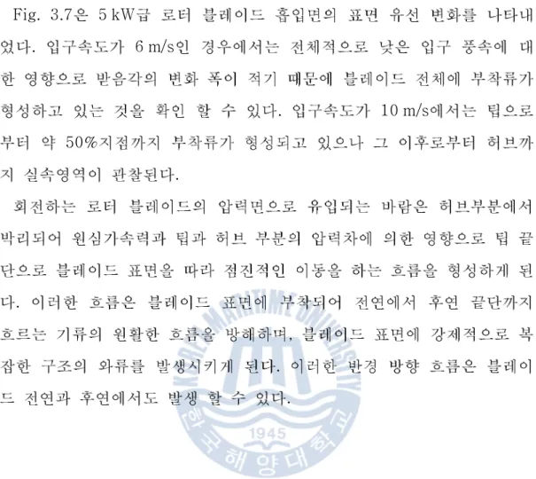
Fig. 3.7 5 kW . 6 m/s . 10 m/s 50% . . , . .
(a) Vin=6 m/s
(b) Vin=8 m/s
(c) Vin=10 m/s
(d) Vin=12 m/s
3 Fig. 3.8 . , . ( ) . (θ) 3 , . , , . Fig. 3.9 Fig. 3.10 3 . Fig. 3.11 6 m/s, 8 m/s, 10 m/s, 14 m/s 3 . Fig. 3.12 .
3d - s t all
In flo w fro m blade r o o t ro o t r ad ial st re am θ r z t ip A dv an c e o f st all A t t a ch edflo w
(a) Vin=6 m/s
(c) Vin=10 m/s
CFD 5 kW BEMT CFD , . BEMT [22] POSEIDON TSR CFD . Fig. 3.13 CFD , . Fig. 3.14 . Fig. 3.15 , Fig. 3.16 .
8 m
2 m/s 100 kW .
.
0.7~1.0 R NACA 5, 6 series foil
,
foil .
0.75~1.0 R NACA63418 foil ,
0.3~0.7 R DU-93-W210 foil . 0.25 R
FFA-W3-301 foil . table 3.5
. Fig. 3.17
Design parameters Values
Prated: Rated power 100 kw
CP: Estimated power coefficient 0.48
: Estimated drive train efficiency 0.9 Vrated: Rated stream velocity 2 m/s
: Sea water density 1024 kg/m3
: Tip speed ratio 5 D: Diameter 8 m
B: Blade number 3
Main Rotor Auxiliary Rotor Unit
Rated Velocity 2 2 m/s Rotor Diameter 4 4 m Rotating Speed 24.72 24.72 RPM Tip Speed Ratio 5 5
No. of Blade 3 3 Airfoil Model FFA-W3-301, DU-93-W-210, NACA63418 FFA-W3-301, DU-93-W-210, NACA63418
y+, , , aspect ratio . CFD . O-type, H-type . Fig. 3.19 , 4,856,256 .
, . Fig. 3.20 . k-ε , 3 .
k-ω SST (Menter, 1993) , . 3 , 7 , 5 . , . (no-slip condition) . . . Table 3.7 .
Case Stream speed [m/s] Rotational speed [rpm] Density [kg/m3] 1 1.6 24.72 1024 2 2 24.72 1024 3 2.4 24.72 1024 4 2.8 24.72 1024 5 3.2 24.72 1024 6 3.6 24.72 1024
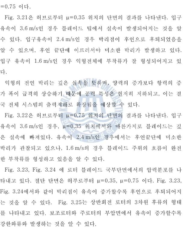
Fig. 3.21, Fig. 3.22 . μ=0.35, μ =0.75 . Fig. 3.21 μ=0.35 . 3.6 m/s . 2.4 m/s , . 1.6 m/s . , , . Fig. 3.22 μ=0.75 . 3.6 m/s , μ=0.35 . 2.4 m/s , 1.6 m/s . Fig. 3.23, Fig. 3.24 . μ=0.35, μ=0.75 . Fig. 3.23, Fig. 3.24 . Fig. 3.25는 상반회전 로터의 3차원 후류의 형태 를 나타내고 있다 보조로터와 주로터의 부압면에서 유속이 증가할수록. 강한와류와 발생하는 것을 알 수 있다.
bound lift-generating vortices free-tip vortices central vortex Vw
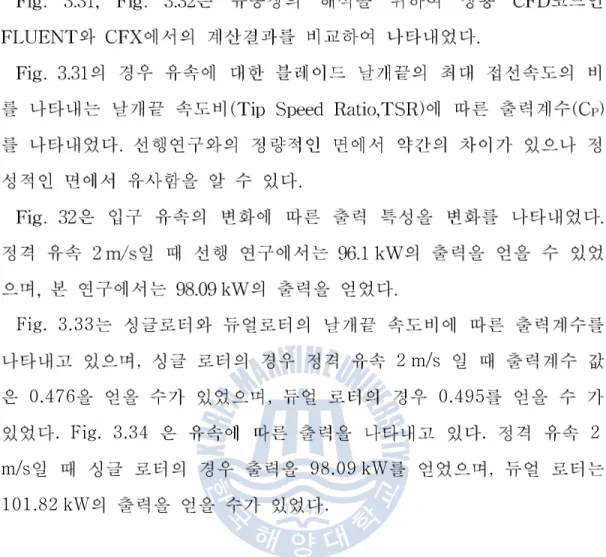
Fig. 3.33 , 2 m/s 0.476 , 0.495 . Fig. 3.34 . 2 m/s 98.09 kW , 101.82 kW .
본 논문이 완성되기까지 세심한 지도와 조언을 아끼지 않으시고 학문의 길을 열어 주신 이영호 지도교수님께 진심으로 깊은 감사를 드립니다 또한 심사과. 정을 통해 부족한 논문을 세심하게 다듬어 빛내 주신 박권하 교수님 김유택, 교수님 감사를 드립니다. 석사 과정동안 CFD에 대한 많은 조언을 해주시며 가르침을 주신 한국 선급 에 김범석 선배님 디엔디이에 최종웅 선배님 상현이 해양에너지 전문 인력, , , 양성사업단에 모장오 선배님 항상 저를 많이 도와주신 유동정보연구실의 식구, 들 현준형 정윤이 지훈이 낙중이 줄라 그리고 먼저 졸업하고 피지로 돌아간, , , , , 디팍 그리고 학위 논문이 완성되기까지 실험실 생활에 항상 큰힘이 되어주고 많은 도움을 주신 창구형 항상 감사합니다 항상 격려해준. 현석이 지훈이 영, , 진이 항상 응원해 주셔서 감사합니다, . 끝으로 오늘이 있기까지 저에게 항상 사랑과 정성으로 모든 것을 주시는 어 머님께 이 논문을 바치며 언제나 힘이 되어준 준오와 5년이란 시간동안 항상 기다려준 은영이에게 고마움을 전합니다.