Contents lists available atScienceDirect
Nuclear Materials and Energy
journal homepage:www.elsevier.com/locate/nmeImproved ERO modelling of beryllium erosion at ITER upper first wall panel
using JET-ILW and PISCES-B experience
D. Borodin
a,⁎, J. Romazanov
a, R.A. Pitts
b, S.W. Lisgo
b, S. Brezinsek
a, I. Borodkina
a,c, A. Eksaeva
a,
E. Safi
d, K. Nordlund
d, A. Kirschner
a, Ch. Linsmeier
a, and JET contributors
1aForschungszentrum Jülich GmbH, Partner of the Trilateral Euregio Cluster (TEC), Institut für Energie- und Klimaforschung – Plasmaphysik, 52425 Jülich, Germany bITER Organization, Route de Vinon sur Verdon, 13067 St Paul Lez Durance, CS90 046 Cedex, France
cNational Research Nuclear University MEPhI, 31, Kashirskoe sh., 115409 Moscow, Russia dUniversity of Helsinki, PO Box 43, 00014, Finland
A R T I C L E I N F O Keywords:
Beryllium Erosion ITER first wall JET ITER-like wall ERO code Modelling
A B S T R A C T
ERO is a 3D Monte-Carlo impurity transport and plasma-surface interaction code. In 2011 it was applied for the ITER first wall (FW) life time predictions[1](critical blanket module BM11). After that the same code was significantly improved during its application to existing fusion-relevant plasma devices: the tokamak JET equipped with an ITER-like wall and linear plasma device PISCES-B. This has allowed testing the sputtering data for beryllium (Be) and showing that the “ERO-min” fit based on the large (50%) deuterium (D) surface content is well suitable for plasma-wetted areas (D plasma). The improved procedure for calculating of the effective sputtering yields for each location along the plasma-facing surface using the recently developed semi-analytical sheath approach was validated. The re-evaluation of the effective yields for BM11 following the similar revisit of the JET data has indicated significant increase of erosion and motivated the current re-visit of ERO simulations.
1. Introduction
The life time of ITER beryllium (Be) first wall (FW) plasma-facing components (PFC) as well as other issues impacting the availability of the fusion device (e.g. tritium (T) retention due to co-deposition with Be and Be-induced sputtering of tungsten divertor PFCs) are strongly de-pendent on the Be erosion and transport in the boundary plasma[2,3]. In recent years, a number of studies at JET[4,5]equipped with the ITER-like wall (ILW) and on the PISCES-B linear plasma device[6,7] have helped to improve the data for physical sputtering (PhSp)[8]and demonstrate the significance of the chemically-assisted physical sput-tering (CAPS)[9]. These PhSp data are used in the ERO 3D Monte-Carlo plasma-surface interaction (PSI) and impurity transport code, which has been widely deployed for Be erosion studies, including modelling of the PSI on a single FW panel “blanket module 11” (BM11) in the vici-nity of the secondary X-point region in ITER[1]. It was shown that net erosion is nearly proportional to the effective sputtering yields as-sumed. However, other effects like distribution of the plasma para-meters along the PFC surface, magnetic shadowing, local angle of magnetic field with the surface and local transport and re-deposition of Be are also of importance. They determine the point, where net erosion
is at its maximum, and the balance between gross erosion and deposi-tion at this (as well as any other) locadeposi-tion.
The significance of the following effects has been demonstrated by ERO application to the existing devices. JET-ILW applications have shown the importance of angular and energy distributions of sputtering ions D+, Ben+determined to a large extent by the acceleration in the magnetic surface sheath. The angular distribution is especially im-portant at grazing angles of the B-field to the PFC surface, treated now using a new semi-analytic approach[10]which leads to a significant correction (increase up to factor 2 at certain BM locations) of the ef-fective sputtering yields used in earlier ERO predictive modelling for ITER[1]. From the other side, spectroscopic measurements interpreted with ERO indicate that, at least for the plasma-wetted areas, the more optimistic ITER life time predications [1] based on the “ERO-min” sputtering assumptions should be used (Section 2), which are based on the large (50%) D content in the surface interaction layer. This fit is ∼4 times lower than the binary-collision approximation (BCA) [8] pro-duced by the SDTrimSP code for the pure Be surface.
Application of ERO to PISCES-B has complemented the JET-ILW experience. Continuous plasma operation and straightforward geo-metry are advantageous for interpretive simulations. Normal incidence
https://doi.org/10.1016/j.nme.2019.03.016
Received 15 August 2018; Received in revised form 19 March 2019; Accepted 20 March 2019 ⁎Corresponding author.
E-mail address:d.borodin@fz-juelich.de(D. Borodin).
1See the author list of ``Overview of the JET results in support to ITER” by X. Litaudon et al., Nucl. Fusion 57 102001.
Available online 18 April 2019
2352-1791/ © 2019 The Authors. Published by Elsevier Ltd. This is an open access article under the CC BY-NC-ND license (http://creativecommons.org/licenses/BY-NC-ND/4.0/).
mulations[1]using the improved understanding and updated effective yields (Section 3).Section 4presents the main results, discusses the erosion/deposition balance along the BM11 surface and model limita-tions.Section 2contains a concise description of the current status of the sputtering data used, including the role of CAPS in the view of in-sight brought by the recent simulations[11]. For the revisit discussed in this paper, we utilize the very same general version of the ERO code, despite recent development of the more advanced, however essentially different ERO2.0 [12]. The aim of the current work is to check the interplay of the erosion-deposition balance using the new effective yields, however keeping the simulation case similar to the earlier one without the impact of improved plasma parameter extrapolation, de-tailed wall geometry and refined shadowing, which would confuse the comparison.
2. Basic sputtering data used in the simulations
The physical sputtering yield dependence on the angle of the sput-tering species at which they fall to the surface can be factorized[8]as an “angular part” (see(1)inSection 3). The normal incidence part of the yield (Fig. 1, left) is often at the focus of the data validation efforts at various devices. However, due to large scattering of the experimental data, which are partially explainable by the difficulty of measurement interpretation (angular part is often neglected despite its significance), ERO utilizes the fits [13]based on the combination of the BCA and molecular dynamics (MD) simulated points which are of particular significance at the lower impact energies close to the sputtering threshold. The “ERO-max” fit is based on simulations for pure Be
and leads to large statistical errors shown inFig. 1, right. The MD-OKMC yields have a maximum at Ein∼100 eV though BCA yields reach maximum at larger impact energies. MD simulations allow following the Be that was sputtered as molecules (mostly BeD according to MD-OKMC[11]) and separate the pure physical sputtering (PhSp) from the chemically assisted one (CAPS), whereas BCA does not include most of the chemical effects.
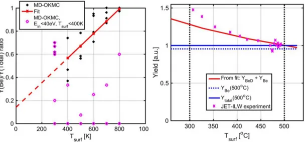
To get a feeling about the surface temperature Tsurfeffect on the PhSp to CAPS relation, the MD-OKMC points relevant for the parameter range characteristic for JET-ILW experiment[9](points at Ein< 40 eV and Tsurf< 400 K are excluded) were used to produce a linear fit for the PhSp fraction in the total yield: PhSp/(PhSp+CAPS) (Fig. 2, left). The CAPS suppression at Tsurf= 820 K was ensured by the fitting procedure. Surprisingly, such simple approach allows reproducing the decay of CAPS observed in[9]by shape and Tsurfscale (Fig. 2, right). The ab-solute CAPS fraction at low temperatures is about ∼30% of the total in comparison to ∼50% in the experiment. It should be noted that these are first steps aimed mostly to get a general insight about the role of CAPS. It is also of importance to mention that ITER is expected to op-erate with significantly colder first wall than JET excluding the PFC heating by plasma (all JET measurements are made for Tsurf above 200 °C) which may increase the significance of CAPS for the total ero-sion of Be in ITER.
3. Revisit of ERO simulations for ITER
The new ERO simulations assume exactly the same geometry of the critical FW element BM11, plasma parameters, magnetic configuration
Fig 1. The normal incidence sputtering yields (left): systematically used by ERO for ITER, JET, PISCES-B “ERO-min” and “ERO-max” as well as various BCA (original simulated data tables 2002 and the same data fitted by the general formula in 2007[8]) and MD[11]simulations. The right figure shows the MD-OKMC data[11] with statistical error bars together with the “ERO-min” fit scaled using the factor F(Tsurf), coming from the linear fit shown inFig. 2.
and shadowing pattern resulting from it as in[1]. The plasma config-uration and parameters are for the baseline Q = 10 ITER discharges [15].Fig. 3illustrates the poloidal position of the BM11 (1a) and its toroidal shape (Fig. 3e, f).3b, c, d show the ERO simulated Be erosion and deposition along the BM11 surface. The main difference to the earlier (2011) simulations are the effective sputtering yields depicted in Fig. 5 and discussed below. The point of maximal erosion to the left from the left ridge of the BM11 has remained approximately at the same
location (Fig. 3c). The erosion near the right ridge has considerably increased and become comparable to the one on the left side. Still, the same toroidal profile as in[1](marked inFig. 3c, e) can be used to study the erosion/deposition balance.
It should be noted that the ERO simulations used inFig. 3 are without Be impurity, though in some of our simulations an assumed concentration of Be in the backgrouhnd plasma represents the material migrating from other PFCs. This effect does not change the general Fig 2. A linear fit for the Be yield to total yield ratio (left) for the MD-OKMC data[11]. The points at low Teand Einare excluded. The fit allows to reproduce the general behaviour (right) of the total erosion observed during JET-ILW experiment[9].
Fig 3. Illustration of the general geometry of the simulation case: a) The poloidal cross-section of ITER including the spatial distribution of the electron temperature, separatrix, the position of the BM11 and the first wall contour; b) ERO simulated distribution of erosion by the D+background plasma ions (without the ERO traced particles); e, d) net erosion and deposition of Be along the BM11 plasma-facing surface; white dotted lines show the B-field direction; the revised simulations are similar in many aspects to the[1]results; e) BM11 in 3D; f) toroidal shape of BM11 and FLFS touching its ridges. Yellow bar at e) and c) shows the position of the toroidal profile depicted in theFigs. 6and7.
based on the effective sputtering yields obtained by the averaging of the basic sputtering data (discussed in Section 2, “ERO-min”) with the appropriate distributions of the ion energies Einand angles α on impact:
= =
Yeff( , )T Y E( , ) Y(0, )* (A E , ) ,
e in in (1)
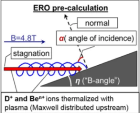
where η is the local surface angle with magnetic field B, Teis the local electron temperature at the sheath entrance and A(Ein, α) – the angular part of the sputtering yield. These distribution come from the con-sideration of the model situation depicted inFig. 4for each BM11 lo-cation. In general, more parameters can affect Yeff, for instance plasma density or deliberate surface biasing like at PISCES-B, however for the considered case it is just a 2D function. The yield angular part in(1)is discussed in [4]; it comes from the BCA simulations[8]and its dis-cussion is out of the scope of the present paper.
In 2011 the dedicated ERO preliminary runs for D+and Be ions were utilized to obtain the (Ein, α) distributions. However, later on this approach was substituted by the semi-analytical approach[10], which uses CPU power more efficiently and free of numerical issues due to strong sheath E-field gradients. The new effective sputtering yields (Fig. 5), which have motivated the revisit, were obtained in the frame of the very same procedure, which was applied earlier for JET and PISCES-B (only energy distribution of sputtering ions matters for the latter) ERO simulations. The main difference is for Yeff
Be ← D (Fig. 5, left) reaching a factor ∼2 for large inclinations of the PFC surface with the B-field, thus at toroidal boundaries of BM11 (B is nearly parallel to the surface at the ridges). Larger inclination also leads to a higher plasma ion flux determining the gross erosion maximum location (Fig. 3b).
4. Results and discussion
Fig. 6 shows the net erosion toroidal profiles (Fig. 3c) extracted from the ERO simulations using Yeffbased on the “ERO-min” fit. The Y
(Ein, α) are averaged by distributions of Ein, α obtained using the semi-analytical approach for the trajectories in the surface sheath. The role of
larger yields for the self-sputtering compared to the lighter D ions. However, the D+sputtering flux decreases according to the electro-neutrality condition:
= + + + + + …
ne 1*n(D ) 3*n(Be )3 4*n(Be )4 (2)
Note, that a single Be4+ion is equivalent to 4 D+ions in the sput-tering flux, however the self-sputsput-tering yields are typically significantly larger. At the end due to the latter the gross erosion slightly increases with growing impurity content, however this increase of erosion is over-compensated by the increase of the deposition from the back-ground plasma. The reflection of Be is negligible. The resulting net erosion, gross erosion and deposition profiles are different including the maxima position.
Obviously, the erosion of Be PFCs including BM11 is one of the main factors determining the Be concentration in the plasma. The self-con-sistent runs including the whole of ITER FW and its volume are possible only using the new ERO2.0[12]. It takes into account the realistic 3D wall geometry based on the technical drawings. Also, it utilizes a more advanced approach for the extrapolation of the edge plasma profile below the wall contour determined by the poloidal BM ridges facing the plasma.
The CAPS discussed inSection 2can further increase the Be PFC gross erosion up to 30%−50%, however this process strongly decreases at large Tsurf. This process is clearly proportional to the D+ion flux, thus, the places where CAPS will be most significant should also be relatively hot due to the heat loads, which may reduce the CAPS. Many parameters for CAPS are uncertain: the yields including the dependence on angles and energies of the sputtering ions, the type and initial an-gular distributions of released atoms or molecules. The erosion, in-creased due to CAPS contribution, may be partially compensated by the increased Be plasma concentration and thus, re-deposition. One can expect that CAPS will not have too dramatic impact on the ITER FW life time. On the other hand, the decay of BeD and other Be-containing molecules in the plasma will cause significantly different transport, which may have impact on Be migration and D (T) co-deposition. The reaction data for the BexDydissociation and ionization in plasma are scarce[16]and uncertain, only 3 reactions are implemented in ERO and validated[17]by application to PISCES-B.
Using the recent ERO experience and improved code infrastructure, it was shown that plasma parameters and shadowing patterns on the BM11 surfaces should be corrected. For instance, a significantly lower
newill lead to a decrease of erosion. The more detailed 2D mapping of the plasma parameters has revealed that the Teat sheath entrance will not be constant at Te= 10 eV along the BM11 surface as in the 2011 ERO runs and the current simulations, but may be ∼3–5 eV lower at certain locations. Fig. 5contains the effective yields for Te = 5 eV, which can be significantly, up to factor ∼2, lower than for 10 eV.
Sputtering by the CX plasma ions is a dominant effect in the sha-dowed areas [18,12]. Including this effect will also affect Be re-de-position.
Fig 4. Model situation considered for generation of the energy Einand angle α distributions on the ion impact with the surface inclined by the angle η with the B-field (∼4.8 T at ITER B11 location).
5. Summary and conclusions
This work presents a revisit of the ERO code simulations[1] moti-vated by the update of the effective sputtering yields due to the semi-analytic approach for ion trajectories in the surface magnetic sheath [10]. It was also important to confirm that multiple technical and nu-merical improvements in the code, which were incorporated during the application to the existing plasma devices with Be (the JET-ILW to-kamak and PISCES-B linear device), have not affected the earlier re-sults.
The paper gives also a status of the currently available sputtering data, including the validated at JET and PISCES-B “ERO-min” fit and the most recent MD-OKMC simulations. The possible role of CAPS is discussed, including a fit allowing the JET-ILW experiment on the CAPS suppression by the surface temperature to be reproduced to a certain extent[9]. The CAPS data remains scarce and uncertain, moreover the uncertainties related to simulation and extrapolation of the background plasma parameters (ERO input) are even higher. Therefore, in the present revisited ERO simulations only physical sputtering is included. The increased effective yields lead to the increase by factor ∼2 of the net erosion in relation to that predicted in 2011. As always, such predictions are dependent to zero order on the assumptions made for
the ITER background plasma under burning plasma conditions (ITER baseline Q = 10 pulses). Measurements of far SOL plasma parameters on current devices are still sufficiently diverse that no firm extrapola-tion can be made with confidence for ITER, which is thus forced to make conservative assumptions based on worst case findings in present experiments. The uncertainties regarding the plasma operation scenario and predictive modelling may easily exceed the erosion yield change found in this most recent revisit of the Be first wall panel interaction. The erosion near the right ridge of BM11 in new ERO runs is now stronger than found earlier and comparable to that predicted near the left ridge. Beryllium plasma impurity leads predominantly to deposi-tion, which decreases the net erosion, thus the simulations neglecting the Be plasma content give lower limit estimate for the life time of the FWP at the location of BM11.
It is not right, however, to see this work as a correction to the predictions in[1], because it considers an improvement for just one of several competing factors which may have an impact. In general:
•
Self-consistent treatment of self-sputtering by Be impurity [12] (unlike an assumed concentration in the background plasma) will lead to more reliable estimates for Be impurity content and charge state as well as Be re-deposition.Fig 5. The effective sputtering yields for Be by D+ ions (left) and Be ions (right) simulated using the semi-analytical sheath approach[10]and pure numerical procedure used in 2011. Te= 5 eV curve for D+impact (left) is multiplied by 2 to simplify the shape comparison with the Te= 10 eV.
Fig 6. Re-visited ERO simulations of net erosion along the toroidal profile at the BM11 surface as marked in theFig. 3c, e. The simulations vary by the effective yields assumed (the simulations assuming the 2011 ones reproduce the earlier ERO simulations[1]).
•
CAPS will contribute to the erosion, moreover it will lead to some-what different transport of dissociating Be-D radicals. Deposition of molecular species can also be different from Be ions.•
More detailed extrapolation of the plasma parameters, refined sha-dowing patterns and inclusion of the erosion due to the CX ion flux are necessary.•
PFC surface morphology, e.g. roughness, can have a comparable effect of factor ∼2–3 on the effective yields[19]For instance, sig-nificant surface morphology change under plasma irradiation was observed at PISCSES-B[20]. However, it should be noted, that postmortem analysis of the JET-ILW Be limiters has shown that
plasma-wetted surfaces remain very smooth.
Therefore, this work prepares and motivates a more profound revisit of the ITER predictions based on global modelling, including the whole FW and vessel volume, using the recently available ERO2.0 code[12].
Acknowledgements
The authors thank R. Doerner and D. Nishijima for the discussions and valuable insight from the PISCES-B side. The computer simulation time is provided by the Jülich Supercomputing Centre. We acknowl-edge grants of computer capacity from the IT Centre for Science in Finland, CSC and the Finnish Grid and Cloud Infrastructure (persistent identifier urn:nbn:fi:research-infras-2016072533).
This work has been carried out within the framework of the EUROfusion Consortium and has received funding from the Euratom Research and Training Programme 2014–2018 under grant agreement
No 633053. The views and opinions expressed herein do not necessarily reflect those of the European Commission or of the ITER organization.
Supplementary materials
Supplementary material associated with this article can be found, in the online version, atdoi:10.1016/j.nme.2019.03.016.
References
[1] D. Borodin, et al., Phys. Scr. (2011) 0140082011. [2] Pitts, et al., J. Nucl. Mater. 415 (2011) S957–S964. [3] S. Carpentier, et al., J. Nucl. Mater. 415 (2011) S165–S169. [4] D. Borodin, et al., Phys. Scr. T159 (2014) 0140576pp. [5] D. Borodin, et al., Nucl. Mater. Energy 9 (2016) 604–609. [6] R.P. Doerner, et al., Nucl. Fusion 52 (2012) 103003. [7] D. Borodin, et al., Nucl. Mater. Energy 12 (2017) 1157–1162. [8] W. Eckstein, Top. Appl. Phys. 110 (2007) 33–187. [9] S. Brezinsek, et al., Nucl. Fusion 54 (2014) 103001. [10] I. Borodkina, et al., Nucl. Mater. Energy 12 (2017) 341–345. [11] E Safi, et al., J. Phys. D 50 (2017) 2040037pp.
[12] J. Romazanov et al., invited at PSI-2019, Nucl. Mater. Energy 18 (2019) 331–338. [13] D. Borodin, et al., J. Nucl. Mater. 438 (2013) S267–S271.
[14] G. De Temmerman, et al., Nucl. Fusion 48 (2008) 075008. [15] S.W. Lisgo, et al., J. Nucl. Mater. 438 (2013) S580–S584.
[16] I. Sukuba, et al., J. Mol. Model. 23 (2017) 203 https://doi.org/10.1007/s00894-017-3362-4.
[17] C. Björkas, et al., Plasma Phys. Control. Fusion 55 (2013) 074004. [18] A. Lasa, et al., Nucl. Fusion 58 (2018) 016046.
[19] A. Eksaeva et al., Nucl. Mater. Energy 19 (2019) 13–18. [20] R.P. Doerner, et al., J. Nucl. Mater. 438 (2013) S272–S275.
![Fig 1. The normal incidence sputtering yields (left): systematically used by ERO for ITER, JET, PISCES-B “ERO-min” and “ERO-max” as well as various BCA (original simulated data tables 2002 and the same data fitted by the general formula in 2007 [8] ) and M](https://thumb-ap.123doks.com/thumbv2/123dokinfo/5090316.76705/2.892.62.835.784.1060/incidence-sputtering-systematically-pisces-original-simulated-general-formula.webp)
![Fig 5. The effective sputtering yields for Be by D+ ions (left) and Be ions (right) simulated using the semi-analytical sheath approach [10] and pure numerical procedure used in 2011](https://thumb-ap.123doks.com/thumbv2/123dokinfo/5090316.76705/5.892.131.757.85.328/effective-sputtering-simulated-analytical-sheath-approach-numerical-procedure.webp)
