Design of IIR Notch Filter for Removal of Baseline wander and
Power Line Interference from ECG Signal
Sorawat Chivapreecha, Kobchai Dejhan and Surapan Yimman*
Faculty of Engineering and Research Center for Communication and Information Technology King Mongkut’s Institute of Technology Ladkrabang, Bangkok 10520, Thailand
Tel: +66-2326-4238, +66-2326-4242, Fax: +66-2326-4554 E-mail: {sorawat, kobchai}@telecom.kmitl.ac.th
*Department of Industrial Physics and Medical Instrumentation, Faculty of Applied Science King Mongkut’s Institute of Technology North Bangkok, Bangkok 10800, Thailand
Abstract: This paper proposes a design of IIR notch filter with modified pole placements. The pole angle is derived from quadratic programming to find the appropriate pole position on the unit circle in z-plane in order to achieve the symmetry of the amplitude response. The simulation results are shown when compared with the conventional design technique. Moreover, it uses the TMS320C31 DSP chip for hardware implementation. Finally, the hardware implementation can be applied to removal of ECG baseline wander and elimination of AC power line interference in ECG signal.
Keywords: IIR Notch Filter, Quadratic programming, Optimal Pole placement, ECG
1. INTRODUCTION
Normally, IIR notch filter can be designed by pole-zero placement method which in the conventional design technique [1] which have many problems about asymmetric amplitude response in pass-band. Also, this paper improves the pole position from conventional design technique by using an iterative scheme. The optimal pole placements are found by solving the quadratic programming problem [2-3].
The results from proposed design technique will be implemented on the TMS320C31 DSK board to shows the removal of ECG (electrocardiogram) baseline wander and elimination of AC power line interference.
2. CONVENTIONAL DESIGN METHOD FOR
IIR NOTCH FILTER
The amplitude response specification of ideal IIR notch filter is given by
⎩
⎨
⎧
=
otherwise
e
H
j,
1
,
0
)
(
ωω
0 (1) And the transfer function is shown as follows2 2 1 0 2 1 0
)
cos(
2
1
)
cos(
2
1
)
(
− − − −+
−
+
−
=
z
r
z
r
z
z
z
H
ω
ω
(2)The zeros are constrained to locate on the unit circle at notch frequency
ω
0 and poles are at the same radial line as zeros. For the stability, pole radiusr
must be smaller than one. Whenr
approaches unity, amplitude response becomes an ideal notch filter. Also, the radiusr
can be controlled the bandwidth of notch filter.Follow by this design method, it gets the notch frequency which is exactly at
ω
0but it has the limitations on asymmetric pass-band gain and cannot determine the pass-band gain according to the desired specifications [4]. This problem causes from the inappropriate pole position. Also, the quadratic programming can be used to search the new optimal pole position to solve the asymmetric and undetermined pass-band gain.3. OPTIMIZATION DESIGN METHOD USING
QUADRATIC PROGRAMMING
In order to get symmetrical and can determine the pass-band gain, the quadratic programming [2-3] which uses the iterative scheme for solving the solution of quadratic equation using to search the optimal pole position. Improve the transfer function in eq. (2) as follows,
)
(
)
(
)
cos(
2
1
)
cos(
2
1
)
(
1 2 2 2 1 0z
A
z
B
k
z
r
z
r
z
z
k
z
H
p=
+
−
+
−
=
−− − −ω
ω
(3)Let
a
=
cos(
ω
p)
, whereω
p is pole angle. The assumption in order to define the cost function is shown in Fig. 1.0 ω
π
ω
ε
ε
ε ω0− ω +0 ε 1)
(
1
−
H
e
jωFig. 1 Assumption used for define cost function From Fig. 1 and eq. (3), assume k = 1. Also, the cost function can be defined as
ω
ω
ω ω ω ω ωd
e
A
e
B
e
A
d
e
A
e
B
a
J
R j j j R j j∫
∫
−
=
−
=
2 2 2)
(
)
(
)
(
)
(
)
(
1
)
(
ω
ω
ω
ω d e A a q p R j∫
+ = 2 2 ) ( ) ( ) ( (4)ICCAS2005 June 2-5, KINTEX, Gyeonggi-Do, Korea
where the integral region R=[0,
ω
0 −ε
]∪[ω
0+ε
,π
] and)
(
ω
p
,q
(
ω
)
are given by ω ωω
ω
r e j e j p( )=( 2−1) −2 +2cos( 0) − andω
jω re q( )= 2− − (5) The optimization problem in eq. (4) can be solved by the iterative scheme as follows,1 1 2 1 2 1 2 2 ) ( ) ( ) ( ) ( − − − − + + = + =
∫
R k k k k k j k k k k d a a e A a q p a J ω ω ω ρ β α ω (6) whereρ
ω
ω
ω d e A q R j k k∫
− − = 2 1 2 1 ) ( ) (β
ω
ω
ω
ωd
e
A
q
p
al
R j k k∫
− ∗ −=
2 1 1)
(
)]
(
)
(
[
Re
α
ω
ω
ωd
e
A
p
R j k k∫
− −=
2 1 2 1)
(
)
(
Therefore, the parameter can be determined by solving the quadratic programming problem as follows,
k
a
Minimize (7) 1 1 2 1 2 ) ( k = k− k + k− k + k− k a a a Jρ
β
α
Subject to −1≤ak ≤1The cost function of this optimization problem [5] is a parabola curve. Also, the unique closed form optimal solution can be obtained as follows,
1 1 1 1 1 1 1 1 1 1 1 1 1 1 ≤ − ≤ − − < − > − ⎪ ⎪ ⎩ ⎪ ⎪ ⎨ ⎧ −− = − − − − − − − − k k k k k k k k k if if if a ρ β ρ β ρ β ρ β (8)
After get it means the optimal pole position can be obtained. The amplitude response of notch filter becomes symmetrical. However, the pass-band gain cannot been controlled according to the desired specification. Therefore, it must be computed the scaling constant k which is used for controlling the pass-band gain to meet the specifications.
k
a
Since, the amplitude response is symmetry already. Also, the magnitude of transfer function at
ω
=
0
is equal to atπ
ω
=
. Consider in eq. (3) with normalized maximum pass-band gain, it can be get2 0 0
)
cos(
2
1
)
cos(
2
2
1
)
(
)
(
r
r
k
e
H
e
H
p j j+
−
−
=
=
=
ω
ω
π)
cos(
2
2
)
cos(
2
1
0 2ω
ω
−
+
−
=
∴
k
r
pr
(9)4. DESIGN EXAMPLES AND SIMULATION
RESULTS
The design examples have specified the notch frequency at
π
ω
0=
0
.
3
, pole radius r = 0.6, 0.7, 0.8 and 0.9 and normalized the pass-band gain is equal to 1. In case of the conventional design method using eq. (2) and the optimization design method using eq. (3-9) where givenε
=
0
.
0001
π
and terminate the iterative procedure if Jk −Jk−1 ≤0.00001. Fig. 2 shows the convergence of algorithm that uses the initial valuesa
0=
cos(
ω
0)
. 0 2 4 6 8 10 12 14 16 18 -3 -2.5 -2 -1.5 -1 -0.5 0 0.5 1 1.5 2 No. of Iterations (k) V a lu es o f Jk m in( ak) r = 0.6 r = 0.7 r = 0.8 r = 0.9(a) Values of minimized cost function.
0 2 4 6 8 10 12 14 16 18 0.58 0.6 0.62 0.64 0.66 0.68 0.7 0.72 No. of Iterations (k) V al u es of ak r = 0.6 r = 0.7 r = 0.8 r = 0.9 (b) Values of cos(
ω
p). Fig. 2 Convergence curve of algorithmTABLE I
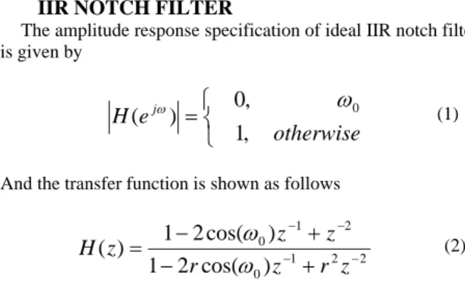
RESULTS FROM CONVENTIONAL DESIGN AND OPTIMIZATION DESIGN METHOD FOR IIRNOTCH FILTER
ω
0
.
3
π
0
=
Zero Position Pole Position Pole Angle (rad) k Conventional Design 0.58778 ± j0.80901 0.35267 ± j0.48541 ± 0.94247 1 r = 0.6 Optimal Design 0.58778 ± j0.80901 0.39969 ± j0.44748 ± 0.84175 0.68000 Conventional Design 0.58778 ± j0.80901 0.41144 ± j0.56631 ± 0.94247 1 r = 0.7 Optimal Design 0.58778 ± j0.80901 0.43790 ± j0.54611 ± 0.89493 0.74500 Conventional Design 0.58778 ± j0.80901 0.47022 ± j0.64721 ± 0.94247 1 r = 0.8 Optimal Design 0.58778 ± j0.80901 0.48198 ± j0.63850 ± 0.92419 0.82000 Conventional Design 0.58778 ± j0.80901 0.52900 ± j0.72811 ± 0.94247 1 r =0.9 Optimal Design 0.58778 ± j0.80901 0.53194 ± j0.72597 ± 0.93843 0.90500
The computed values of pole-zero position, pole angle and scaling constant that is used for pass-band gain controlling is shown in Table I and Fig. 3 shows the amplitude response that obtained from conventional design method when compared with the optimization design method using quadratic programming. 0 0.1 0.2 0.3 0.4 0.5 0.6 0.7 0.8 0.9 1 0 0.2 0.4 0.6 0.8 1 1.2 1.4 1.6 Normalized Frequency N o rm al iz ed A m pl it u de r = 0.6 r = 0.7 r = 0.8 r = 0.9
(a) Conventional design method
0 0.1 0.2 0.3 0.4 0.5 0.6 0.7 0.8 0.9 1 0 0.2 0.4 0.6 0.8 1 1.2 Normalized Frequency N o rm al iz ed A m pl it u de r = 0.6 r = 0.7 r = 0.8 r = 0.9
(b) Optimization design method
Fig 3 Amplitude response at notch frequency at
ω
0=
0.3
π
for various pole radius5. APPLICATION TO REMOVAL OF ECG
BASELINE WANDER AND POWER LINE
INTERFERENCE
In particular, medical signal processing of ECG signals, there is a need to eliminate the baseline wander that caused from very low frequency components and the AC power line frequency [6-7]. Also, in this experiment will be divided to 2 experiments. The first, for removal of ECG baseline wander which assumed very low frequency is 1 Hz. Therefore, the first IIR notch filter has notch frequency at 1 Hz, sampling frequency 800 Hz and 3dB bandwidth 1 Hz which correspond to pole radius r = 0.996 with optimal pole angle ± 0.007124 radian. Follow by proposed method can be got the transfer function as follows, 2 1 2 1
992156
.
0
99209
.
1
1
996078
.
0
99209
.
1
996078
.
0
)
(
− − − −+
−
+
−
=
Z
Z
Z
Z
Z
H
and the amplitude response can be shown in Fig. 4.
0 50 100 150 200 250 300 350 400 0.5 0.6 0.7 0.8 0.9 1 1.1 Frequency (Hz) No rm a li ze d Am p lit u d e
Fig. 4 Amplitude response of removal of ECG baseline wander filter
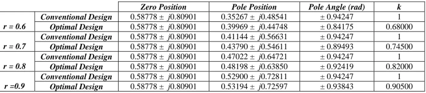
The ECG signals obtained from the ECG simulator of Lionheart Technologies, Inc. by setting the heart beat is 90 BPM (beat per minute). The result of removal of ECG baseline wander can be shown in Fig. 5. Signal in upper trace shows ECG with baseline drift and signal in lower trace shows filtered signal.
Fig. 5 Removal of ECG baseline wander
In fact, the recommendations of the American Heart Association state that the frequency components above 0.05 Hz should not be removed. Also, the very low frequency should be closed to DC. The filter coefficients for notch frequency close to DC have high sensitivity which cannot implement using Direct Form II structure but the filter realization used for implementation is Direct Form II structure. Also, this experiment will be assumed very low frequency is 1 Hz. This problems can be cleared using low sensitivity structure or reduce the sampling rate.
The second experiment, to eliminate of AC power line interference which assumed power line frequency is 50 Hz. Therefore, the second IIR notch filter has notch frequency at 50 Hz, sampling frequency 800 Hz and 3dB bandwidth 5 Hz which correspond to pole radius r = 0.98 with optimal pole angle ± 0.39223 radian. Follow by proposed method can be got the transfer function as follows,
2 1 2 1 96151 . 0 8122 . 1 1 980755 . 0 8122 . 1 980755 . 0 ) ( − − − − + − + − = Z Z Z Z Z H
and the amplitude response can be shown in Fig. 6.
0 50 100 150 200 250 300 350 400 0 0.2 0.4 0.6 0.8 1 Frequency (Hz) N o rm al iz ed A m pl it u de
Fig. 6 Amplitude response of elimination of AC power line interference filter
The result of elimination of AC power line interference can be shown in Fig. 7. Signal in upper trace shows ECG with 50 Hz AC power line frequency and signal in lower trace shows filtered signal.
Fig. 7 Elimination of AC power line interference
6. CONCLUSIONS
The optimal IIR notch filter design using quadratic programming for modified pole placement result in symmetric and can determine the pass-band gain according to the desired specifications. The obtained results optimal design are better than when compared with the conventional design technique but more complicated design procedures. Furthermore, it can be applied to removal of ECG baseline wander and eliminate the AC power line noise frequency from ECG signal.
REFERENCES
[1] J. G. Proakis and D. G. Manolakis, “Digital Signal Processing Principle, Algorithm and Applications,” Prentice-Hall, 1996.
[2] R. A. Roberts and C. T. Mullis, “Digital Signal Processing,” Addison-Wesley, 1987.
[3] C. C. Tseng and S. C. Pei, “Stable IIR Notch Filter Design with Optimal Pole Placement,” IEEE Trans. Signal
Processing., Vol. 49, No. 11, pp. 2673-2681, November
2001.
[4] S. Yimman, W. Hinjit, S. Sriboonsong, M. Puangpool and K. Dejhan, “IIR Notch Filter Design with Modified Pole-Zero Placement Algorithm,” Proc. IEEE Int. Symp. Signal
Processing and InformationTechnology (ISSPIT 2003),
Darmstadt, Germany, December 2003.
[5] L. V. Fausett, “Applied Numerical Analysis Using Matlab,” Prectice-Hall, 1999.
[6] J. A. Van Alste and T. S. Schilder, “Removal of Baseline Wander and Power Line Interference from ECG by an Efficient FIR Filter with a Reduced Number of Taps,”
IEEE Trans. Biomedical Engineering, Vol. 32, pp.
1052-1060, December 1985.
[7] J. P. Marques de Sa, “Digital FIR Filtering for Removal of ECG Baseline Wander,” J. Clinical Engineering, Vol. 8, pp. 235-240, 1982.