60-1 / H. Yoshikawa
IMID 2009 DIGEST •
Abstract
Recently, researches on holographic 3D video display are getting very active, though the goal is still challenging. This paper describes recent research activities on the holographic video system in Japan. It includes hologram calculations and acquisitions as well as displays.
1. Introduction
The idea of “holographic television” had already existed in 19651. At that time, however, it seemed almost impossible to realize a practical display system, because the required amount of information is too huge compared with two-dimensional images. In addition, required resolution for the spatial light modulator (SLM) is roughly same as the wavelength of the visible light.
Recently, researches on holographic video display are getting very active again in Japan. This paper describes some of recent research activities on the holographic video system in Japan. It includes hologram calculations and acquisitions as well as display systems.
2. Acquisition and Generation
Holographic fringe pattern can be easily captured by an image sensor such as a CCD, just by replacing a photo-sensitive material. This technique is widely used in so-call “digital holography,” the hologram is captured by the image sensor and digitally reconstructed by the computer. It is also possible to realize the full color hologram camera with three lasers and single CCD with a color filter2.
The full parallax hologram of the real scene is calculated from the integral photographic image taken by the two-dimensional lens array and single HDTV camera3. Although, the hologram is made from the array of 2-D images, the reconstructed image gives focus effect to the viewer. They have also developed
the special hardware with 20 DSPs (digital signal processor) and FPGA (field programmable gate array) to convert the captured IP image to the hologram. Each DSP acts as the fast Fourier transform processor and the system can generate thirty full color holograms per second.
T. Ito and his group at Chiba University have been developing special hardware for reconstruction and generation of hologram. Their latest model, HORN-5 system4 can generate the hologram of 1,408 x 1,050 pixels with 10,000 object points in about 23 ms. The system consists of four HORN-5 boards and the each board has four FPGA chips. They are also studying hologram calculation on a graphics processing unit. The CGH is calculated in 298 ms whose size is 1,920 x 1,080 pixels with 5,120 object points.
(a) Fresnel hologram.
(b) Compensated Phase Added Stereogram. Fig. 1. Comparison of reconstructed images by
simulation.
Research Activities on Holographic Video in Japan
Hiroshi Yoshikawa
Dept. of Electronics & Computer Science, Nihon Univ., Funabashi, Chiba 2748501, Japan TEL:81-47-469-5391, e-mail: [email protected]
60-1 / H. Yoshikawa
• IMID 2009 DIGEST
H.-J. Kang et. al. have implemented compensated phase-added stereogram (CPAS) on the GPU5. The CPAS can be generated very fast because it can be calculated by fast Fourier transforms (FFT). Reconstructed images calculated by Fresnel diffraction from the Fresnel hologram and CPAS are shown in Fig. 1. The object consists of about 1,500 points used to make an image of an airplane, and the resolution of the hologram is 1,024 x 1,024 pixels. As shown in Fig. 1, the reconstructed image of CPAS is not as sharp as the Fresnel hologram. However, the computation time of the CPAS on the GPU is 130 thousand times faster than that of the Fresnel hologram on the CPU.
Since an object of the image hologram is located very close to the hologram, the chromatic aberration caused by the difference of wavelength becomes small. Therefore, the hologram can reconstruct image with white light illumination. The image hologram also has an advantage for the fast hologram calculation6. For computer-generated hologram, it is enough to calculate light whose diffraction angle is equal or smaller than the maximum diffraction angle of the SLM. As a result, required computational area becomes smaller than the entire hologram and it means required calculation amount also becomes smaller. The calculation area decreases by the decrease of diffraction angle, when the position of the object point is same. We use a virtual window that is placed away from the hologram. If we calculate only the light that passes the virtual window, the calculation amount is decreased from the entire hologram area. If the virtual window is configured so that the light of the maximum diffraction angle or smaller of LCoS may pass, the performance of LCoS is not wasted. In addition, by putting the object point closer to the hologram makes the calculation area much smaller.
We have also investigated to apply a distance look-up table (DLUT) method for the image hologram7. Since image points are located close to the hologram, required look-up table size also becomes much smaller than that of the Fresnel hologram. For example, if we assume a pixel pitch of the hologram is 10 µm, the maximum diffraction angle for wavelength λ = 500 nm is 1.43 degrees. Therefore, the required calculation area on the hologram is (0.25 mm)2 when the object point is located at 10 mm from the hologram. This area includes 625 pixels on the hologram and the pixel number is same as the required look-up table size for single depth. If we
use 1,000 discrete depths sampling, total look-up table size is still less than one million samples, while the size for Fresnel hologram is 1.8 GigaBytes8. Small table size is very important to improve cache memory hit ratio for fast hologram generation.
1 10 100
100 1,000 10,000 100,000 1,000,000 Number of Point Sources
F ram e Rat e [f ra m es /s ] Image Hologram Image Hologram with DLUT
DLUT+3Thread
Fig. 2 . Frame rate of the real-time hologram generation.
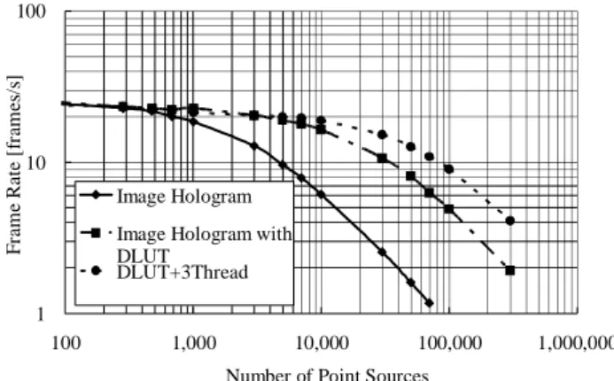
The real-time hologram generation is done with the full color holographic video display, which consists of three LCoSs (liquid crystal on silicon) as the SLM6. The LCoS panel has 1,408 x 1,058 pixels with 10.4 µm pitches and 8-bit grayscale levels. Computational speed is measured on a personal computer whose CPU is Intel Core 2 Quad 2.66 GHz. Since the processor has 12 MByte of L2 cache memory, it is enough to store the distance look-up table in it and high speed access is expected. The pixel number of the calculated hologram is 1,400 x 1,050. Figure 2 shows the frame rate of the real-time hologram generation, including all overhead times such as data transfer to the video memory. In Fig. 2, “Image Hologram” is calculated with the difference method, “Image Hologram with DLUT” is calculated with the distance look-up table, and “DLUT+ 3Thread” means three threads are used for red, green and blue holograms for parallel calculation with the distance look-up table. Since some object points consist of two or three primitive colors like white, we assume one point means one color. For example, since a white point consists of red, green, and blue, it is counted as three points. From Fig. 2, the computation speed of the distance look-up table is 3.1 times faster than that of the difference method with 10,000 object points. The difference method is about 16 times faster than the rigorous calculation. Therefore, the proposed distance look-up table is
60-1 / H. Yoshikawa
IMID 2009 DIGEST •
roughly 50 times faster than the rigorous method. With three threads calculation, another 2.4 times speed up is obtained against single thread. Note that the precision of the distance look-up table is same as the rigorous calculation, while the difference method utilizes approximations. From Fig. 2, the frame rate of 19 fps (frames per second) is obtained for three threads calculation with 10,000 object points. Even in the case of 100,000 object points, the frame rate still keeps 9 fps. These frame rates are suitable for interactive object manipulation and real-time animation.
3. Holographic Video Displays
A liquid crystal (LC) panel for a video projector is often used for holographic television. However, its pixel size and pixel number are not enough for practical holographic 3D display. Therefore, multi-panel configuration is often used to increase the viewing angle and displayed image size.
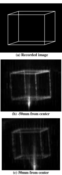
We have proposed a novel method to increase the viewing angle with single LC panel9. At the first, the whole resolution is divided into small segments in vertical. And then they are rearranged in horizontal. According to the method, it could make the wide and high resolution SLM in horizontal. Although, the resolution is decreased in vertical direction, the observer can get a 3D effect from the hologram, because the human get more 3D information in horizontal direction. The method is implemented by a mirror module to reconfigure the beam shape reflected by the LC panel. An LCoS is used to display the hologram. The beam reflected by the half-silvered mirror illuminates the LCoS. The LCoS displays the fringe, which is calculated by the personal computer. The reflected and diffracted beam on the LCoS is imaged on the lower mirrors of the mirror module through the 4f lens set. Then, the part of the beam is reflected to the corresponding upper mirror and beams are aligned in horizontal. Finally, the reconfigured beam by means of the mirror module forms a reconstructed image in the air. The reconfigured beam has double resolution in horizontal direction. Inversely, the vertical resolution is decreased half. In the experiment, a cube, which is shown in Fig. 3 (a), is employed as the model to generate the hologram. The reconstructed images are shown in Fig. 3 (b), (c). They are taken from left side to right side in the viewing window, whose size is 110 mm x 40 mm at 500 mm from image. The
horizontal viewing angle is measured as 12.5 degrees, which is almost two times wider than that without the mirror module. In Fig. 3, all reconstructed image are clear, and if viewpoint is changed right and left, motion parallax is recognized. Through the proposed method, we could see the displayed holographic image in the wide viewing window.
(a) Recorded image
(b) -50mm from center
(c) 50mm from center
Fig. 3. Recorded and reconstructed images by the optical system (Viewing distance is 50 mm).
60-1 / H. Yoshikawa
• IMID 2009 DIGEST
Another method to redistribute the resolution of SLM is proposed10. The slanted array of four illumination point light sources and 4f lens generates four slanted Fourier-transformed image of SLM aligned in horizontal. This is equivalent to make the horizontal resolution four times and the viewing angle is increased to 14.4 degrees.
To realize a full color holographic video display, people usually uses three different wave-length illumination and three spatial light modulators. To combine lights from SLMs, dichroic mirrors and other optics are used. These elements are already built in the conventional video projector. Therefore, we have built a full color holographic video display with the video projector and a white-light LED6.
The other way to realize a full color display is to illuminate a single SLM with time sequentially switched RGB light sources2, 4.
The new approach for horizontal parallax only display is proposed11. The display uses single high speed digital micro-mirror device (DMD) and horizontal scanner. Since the vertical resolution is same as the DMD, no vertical scan is required. The DMD is driven at the frame rate of 13.3 kHz and the holographic frame rate is 60 Hz. Therefore, it is equivalent to display 222 elemental holograms in horizontal. The displayed hologram size is 73.1 mm by 52.5 mm and has the viewing area of 14.6 degrees.
4. Summary
This paper introduces recent research activities on the holographic video display in Japan. Since the activity is quite high, only limited works can be described. Although there are steady progresses, some breakthroughs are desired particularly on the SLM to develop a practical display system.
5. References
1. E. N. Leith, J. Upatnieks, B. P. Hildebrand and K. Haines, “Requirements for a wavefront reconstruction facsimile system,” J. Soc. Motion
Picture and Television Engineers, 74, p. 893 (1965).
2. Kunihiro Sato, “Record and Display of Color 3-D Images by Electronic Holography,” OSA topical
meeting on Digital Holography and Three-Dimensional Imaging, paper DWA2 (2007).
3. R. Oi, K. Yamamoto, T. Mishina and M. Okui, “Real-time IP-hologram conversion hardware based on floating point DSPs, ” Proc. SPIE, 7233,
p. 723305 (2009)
4. T. Ito and T. Shimobaba, “Real-Time Computation for Electro-Holography,” OSA topical meeting on
Digital Holography and Three-Dimensional Imaging, paper DWD1 (2009).
5. H. J. Kang, T. Yamaguchi, H. Yoshikawa, S.-C. Kim and E.-S. Kim, “Acceleration method of computing a compensated phase-added stereogram on a graphic processing unit,” Applied Optics, 47, p. 5784 (2008).
6. T. Yamaguchi, G. Okabe and H. Yoshikawa, “Real-time image plane full-color and full-parallax holographic video display system,” Optical
Engineering, 46, p. 125801 (2007).
7. H. Yoshikawa, T. Yamaguchi and R. Kitayama, “Real-Time Generation of Full color Image Hologram with Compact Distance Look-up Table,”
OSA topical meeting on Digital Holography and Three-Dimensional Imaging, paper DWC4 (2009).
8. S.-C. Kim and E.-S. Kim, “Effective generation of digital holograms of three-dimensional objects using a novel look-up table method,” Applied
Optics, 47, p. D55 (2008).
9. N. Ohmura, H.-J. Kang, T. Yamaguchi and H. Yoshikawa, “A method to increase the hologram viewing angle by the beam reconfiguration,” Proc.
SPIE, 6912, p. 69120O (2008).
10. Y. Hayashi and Y. Takaki, “Horizontal resolution enhanced hologram to increase horizontal viewing angle,” Proc. SPIE, 6912, p. 69120I (2008).
11. N. Okada and Y. Takaki, “Horizontally scanning holography to enlarge both image size and viewing zone angle,” Proc. SPIE, 7233, p. 723309 (2009).