A Study on the Variation of the Fretting Wear Mechanisms under
Elastically Deformable Contacts
Young-Ho Lee† and Hyung-Kyu Kim
Advanced LWR Fuel Development Division, Korea Atomic Energy Research Institute, Daejeon, Korea
(Received 31 October 2009; Revised 29 November 2009)
Abstract: In this study, fretting wear tests of nuclear fuel rods have been performed by using two kinds of spacer grid springs with a concave and a convex shape in room temperature dry and distilled water conditions. The objectives were to examine the variation of the wear mechanism with increasing fretting cycles and to evaluate the difference of the wear debris detachment behavior at each test environment. From the test results, the wear volume of each spring condition increased with increasing fretting cycles regardless of the test environments. However, the wear rate did not show a regular tendency and apparently changed with increasing fretting cycles. This is because the formation of the wear particle layer and/or the variation of the contact condition between the fuel rod and spring surfaces could affect a critical plastic deformation for detaching the wear debris. Based on the test results, the relationship between the wear behavior of each spring shape and test environment condition, and the variation of the surface characteristics are discussed in detail.
Keywords: Fretting wear, nuclear fuel rod, wear debris, contact shape, spacer grid
1. Introduction
Zirconium alloys are widely used as proven structural materials for nuclear applications due to their high corrosion resistance and thermal neutron economy. Although their wear resistances are much lower than other nuclear-grade materials [1], advanced Zirconium alloys have been developed recently by many fuel venders and utilities for considering the improvement of their corrosion resistances. Because the major role of a nuclear fuel rod is transferring the excess heat generated by a fission reaction to a primary coolant, the application of the above well-known methods for decreasing wear damages is a complicated procedure or is basically unattainable. Among those methods, however, the improvement of a contact condition by changing a grid spring shape is available with a consideration of an economy and the development period. As a result, various spring shapes have been developed in KAERI, and their performance tests have been carried out from a part unit to a full assembly scale.
Early work on wear debris effects of wear damages [2-5] indicated that the wear rate is strongly influenced by the formation of wear debris layers and a subsurface deformation in various test conditions. Recently, Lee et al. [6-9] showed that the wear scar formation and the wear debris behavior
changed dominantly with the contact spring shapes rather than the test environments. One of the noticeable results was that, with increasing number of cycles, the contact force between a fuel rod and an elastically deformable grid spring was gradually decreased due to a depth increase. This means that the fretting wear mechanism was also changed at each spring and environmental condition. Therefore, the purposes of the present work are to examine the variation of the wear mechanism with increasing fretting cycles and to evaluate the difference of the wear debris detachment behavior at each test environment.
2. Experiments
2.1. Specimen
A commercial Zirconium alloy used as a nuclear fuel rod material was prepared in this study. The dimensions of the fuel rod specimen are 50 mm in length, 9.5 mm in outer diameter and 0.575 mm in wall thickness. In order to reduce the initial surface roughness effects, the fuel rod surface was carefully ground with sand paper of a 800 grit size and then its average roughness was maintained at 0.3±0.1 µm. Two kinds of grid spring specimens with the same Zirconium alloy were also prepared by using a plate with 0.46 mm thickness. Spring A has a concave contour, which was intended to have an area contact with a wrapping around the fuel rod in a circumferential direction of the contact region. Since spring B †Corresponding author; [email protected]
28 Young-Ho Lee and Hyung-Kyu Kim
has a convex contour, however, this spring was intended to have a line contact with a fuel rod in an axial direction of the contact region. Fig. 1 shows the schematic views of the spring specimens used in this study. The chemical composition, mechanical properties and spring characteristics are given in Table 1 and 2.
2.2. Fretting wear tester and test conditions
A fretting wear tester for a nuclear fuel fretting was specially designed as shown in Fig. 2. A fuel rod specimen was attached to a vibration jig, which was oscillated in the rod axial
direction with some amount of relative slip amplitude against a fixed spring specimen. During the fretting wear tests, normal and friction loads, relative slip amplitude and vibrating frequency were monitored and stored on a real-time basis by using LabVIEW®. Other detailed characteristics of this system could be found in a previous study [10].
The spring specimen was fixed to a stroke mechanism and moved to the fuel rod specimen until a normal load reached 10 N. After then, the vibration jig that attached a fuel rod specimen was oscillated in the fuel rod axial direction with a peak-to-peak amplitude of 50, 80 and 100µm at a frequency of 30 Hz. All the tests were carried out in room temperature dry (relative humidity of 50±10%) and distilled water up to fretting cycles of 105, 106 and 107.
2.3. Wear analysis
After the fretting wear tests were finished, the fuel rod specimen was acoustically cleaned in acetone for 5 min and dried in compressed air. The worn area was observed by using an optical microscope in order to analyze and measure the wear scar characteristics and the worn area including its length and width, respectively. The wear volume and depth profile were also measured by using a surface roughness tester and their results were compared for each test condition. The worn surface was observed by using SEM to examine the variation of the fretting wear mechanism with increasing number of cycles.
3. Results and discussion
3.1. Wear behavior
Fig. 3 shows the variation of the wear volume with increasing number of cycles in room temperature dry and distilled water. As expected, spring A with a concave shape always showed a higher wear volume than spring B with a convex shape regardless of the test environments. With increasing number of cycles up to 106, the wear volumes of spring A in both environmental conditions rapidly increased when compared with those of spring B. As the number of Fig. 1. Spring specimens used in this study.
Table 1. Chemical composition of the Zr alloy [w/o]
Nb Sn Fe Cr O Zr
1.0 1.0 0.11 - - Bal.
Table 2. Mechanical properties and spring characteristics of the tested Zr alloy
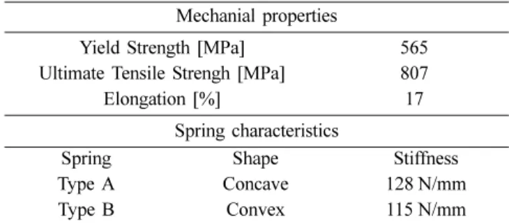
Mechanial properties
Yield Strength [MPa] 565 Ultimate Tensile Strengh [MPa] 807
Elongation [%] 17
Spring characteristics
Spring Shape Stiffness
Type A Concave 128 N/mm
Type B Convex 115 N/mm
Fig. 2. Fretting wear tester for room temperature conditions.
Fig. 3. Variation of wear volume with increasing number of cycles at each test condition.
cycles reached 107, however, spring A shows a higher wear volume in the dry condition while spring B shows that in the distilled water condition. Under a fretting wear condition, detached wear debris could experience severe plastic deformations and then fracture to smaller wear particles between contact surfaces before their release from the contact surfaces. At this time, it is expected that the release behavior of the wear particles and the formation of a load bearing layer due to the agglomeration of the wear particles are greatly affected by the test environment and the contact condition (i.e. spring shape). Therefore, the wear test result at the fretting cycle of 107 pointed out that the wear mechanism of a nuclear fuel rod could be changed with increasing number of cycles.
In addition, it could be confirmed from the result of the slip amplitude effect as shown in Fig. 4. The wear volume of spring B in the dry condition always shows lower values regardless of the slip amplitude and number of cycles. However, a higher wear volume at the fretting cycle of 107 appears for spring A in the dry condition while both springs in the distilled water condition show higher wear volumes at a fretting cycle of 105 even though spring A in the dry condition at a slip amplitude of 100 mm has a similar wear volume compared to both springs in the distilled water condition. At the fretting cycle of 105, a higher wear rate in the distilled water condition could be explained by an easy release of the wear particles from the worn surfaces, but it is insufficient for
applying this wear mechanism to a wear result at a fretting cycle of 107. So, it is necessary to compare the wear depth profile and the worn surface morphology at each spring condition in order to examine the variation of the wear mechanism with increasing number of cycles.
3.2. Worn surface and depth profile
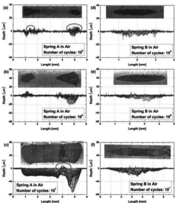
The worn area and wear depth profile were observed and measured by using an OM and a surface profilometer, respectively. As shown in Fig. 5, it is apparent that the wear scar length of spring A has a similar value regardless of the fretting cycles while that of spring B gradually increased. In addition, the positions of the maximum wear depth do not vary with the fretting cycles and the spring shape condition. However, the protruded positions of spring A as noted with circles in Figs. 5(a) and (c) were moved from both end regions to the left region of the maximum wear depth position, which were expected to be generated by a wear debris or transferred from a spring specimen. This result provides evidence of the formation of a wear debris layer with a protruded shape on the worn surface. On the other hand, the protruded positions of spring B were generated at the center region and gradually disappeared with increasing fretting cycles.
From the result of the wear depth profile, it is expected that the small protruded region of spring A experienced a relatively high contact stress, which is similar to the contact behavior of the asperities between two rough surfaces even though the Fig. 4. Effect of slip amplitude on the wear volume: (a) 105
cycles; (b) 107 cycles.
Fig. 5. The results of the wear scar observation and the wear depth measurement with increasing number of cycles: (a) spring A at 105 cycles; (b) spring A at 106 cycles; (c) spring C at 107 cycles; (d) spring B at 105 cycles; (e) spring A at 106 cycles; (f) spring C at 107 cycles.
30 Young-Ho Lee and Hyung-Kyu Kim
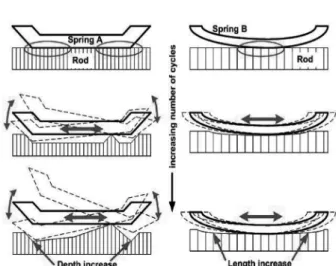
normal force is gradually decreased with increasing number of cycles. So, the load-bearing layer was developed in some parts of the worn surface and it acted as a hinge with a seesaw motion when contacted with an elastically deformable grid spring. It finally results in a localized wear with a third body abrasion. On the other hand, a wear debris layer of spring B was hidden at the center region of the contact surfaces and an elliptical wear scar was developed due to the interaction between the released wear debris and the contact surfaces at both ends. It is concluded that the debris release rate decreased due to such a contact condition of spring B and finally the total wear rate was decreased. The wear debris release mechanism for both spring shapes in the room temperature dry condition is described in Fig. 6.
3.3. Wear mechanism analysis
Fig. 7 shows the results of the worn surface observation by using SEM. At the fretting cycle of 105, both springs show wear debris layers on the worn surface in the dry condition. A fold type layer that is generated by repeatedly thrusting out the agglomerated wear particles appears dominantly in the spring A condition. This layer is not firmly developed enough to accommodate a severe deformation by the formation of a load-bearing layer. However, the spring B condition clearly shows a hardened wear debris layer on the worn surface and the fractured particle size of the wear debris layer is smaller and thinner when compared to the spring A condition. In the distilled water condition, however, deformed folds mixed with pulverized wear particles are clearly shown in both spring conditions and they seem to be detached after a severe plastic deformation. After being detached, this debris interacts within the contact surfaces by a third-body abrasion and then is fractured to small wear particles. At this time, these particles are trapped on suitable sites on the worn surfaces or escape from the contact surfaces. Therefore, wear behaviors for each spring and test condition could be explained by using the debris behavior between the contact surfaces up to 105 cycles.
On the other hand, SEM results at the fretting cycles of 107 show different worn surface morphologies as shown in Fig. 8.
Both springs in the dry condition show that hardened wear debris layers are well developed at the center region of the worn surfaces. But, the difference of the worn surface morphologies between the two spring conditions could apparently be found in the directional characteristics of the agglomerated debris folds at both ends of the contact region. The most important point is that the directional characteristics of these folds provide evidence for a migration path of the generated wear debris and the formation process of the wear scar shape during a fretting cycle increase. In the spring A condition, these folds faced toward the center region where the hardened wear debris layer was developed and protruded. Also, as mentioned above, this region acts as a hinge with a seesaw motion. Therefore, these conditions seem to accelerate Fig. 6. Schematic view of the wear debris release mechanism
at both spring shapes in the room temperature dry condition.
Fig. 7. SEM images of the worn surface at fretting cycle of 105: (a) spring A in dry; (b) spring A in distilled water; (c) spring B in dry; (d) spring B in distilled water.
a localized wear depth increase due to both a third-body abrasion and the repeated formation/fracture of these folds near the contact ends.
In the spring B condition, however, these folds faced in the opposite direction when compared to the spring A condition. It enables us to explain why the wear scar length of the spring B condition gradually increased with increasing number of cycles. Because the hardened wear debris layer at the center region could mostly accommodate the contact load, the smaller wear volume was caused by a small contact load on both ends during an interaction between the wear debris and the contact surfaces even though abrasion traces or scratches also appeared on the worn surface. Therefore, the wear behavior was greatly affected by the contact spring shape when the
hardened wear debris layer was locally generated and reached a specific size as the fretting cycles increased.
In contrast to the dry condition, no distinguishable difference between the two springs in the distilled water condition was found for their worn surface morphologies. Also, it is difficult to detect any noticeable protruded region on the worn surfaces. This is because the formation of the wear debris layer could be prohibited by the distilled water lubrication condition. Consequently, it is thought that the wear volume difference between both springs was determined by the wear debris behavior under different spring contacts when the wear debris was generated from the worn surface after a severe plastic deformation and a fracture of a deformed layer. Therefore, it is concluded that, with increasing number of cycles, the variation of the fretting mechanism between a nuclear fuel rod and the two kinds of grid springs in the room temperature dry and distilled water condition could be explained by the formation of the wear debris layer, the debris removal paths with spring shapes, the directional characteristics of the agglomerated debris folds.
4. Conclusion
Fretting wear tests of nuclear fuel rods have been performed in order to examine the variation of the wear mechanism with increasing fretting cycles by using two kinds of spacer grid springs with a concave (spring A) and a convex (spring B) shape in the room temperature dry and distilled water condition. From these experimental results, the following conclusions are drawn.
(1) The effects of the spring shape and the test environment on the wear mechanism of a nuclear fuel rod could be changed with increasing number of cycles.
(2) In the concave spring condition (i.e. spring A), the load-bearing layer was developed in some parts of the worn surface and it acted as a hinge with a seesaw motion. It finally results in localized severe wear damage. Therefore, the wear behavior was greatly affected by the contact spring shape when the hardened wear debris layer was generated locally and reached a specific size as the fretting cycles increased.
(3) The directional characteristics of these folds provided evidence for a migration path of the generated wear debris and the formation process of the wear scar shape during a fretting cycle increase.
Acknowledgment
This work was supported by Nuclear Research & Development Program of the Korea Science and Engineering Foundation (KOSEF) grant funded by the Korean government (MEST). (grant code: M207060200 05-08M0602-00510)
References
1. Attia, M. H., On the Fretting Wear Mechanism of Zr-alloys, Tribology International, Vol. 39, pp. 1320-1326, 2006. 2. Stott, F. H., The Role of Oxidation in the Wear of Alloys, Fig. 8. SEM images of the worn surface at fretting cycle of
107: (a) spring A in dry; (b) spring A in distilled water; (c) spring B in dry; (d) spring B in distilled water.
32 Young-Ho Lee and Hyung-Kyu Kim
Tribology International, Vol. 31, pp. 61-71, 1998.
3. Jiang, J., Stott, F. H., The Effect of Partial Pressure of Oxygen on the Tribological Behavior of a Nical-Based alloy, N80A, at Elevated Temperature, Wear, Vol. 203-204, pp. 615-615, 1997.
4. Rigney, D. A., Divakar, R., Kuo, S. M., Deformation Substructures Associated with Very Large Plastic Strains, Scripta Metall. et Materials, Vol. 27, pp. 975-980, 1992. 5. Rice, D. A., Characteristics of Metallic Subsurface Zones in
Sliding and Impact Wear, Wear, Vol. 74, pp. 131-142, 1981-82.
6. Lee, Y. -H., Kim, H. -K, Jung, Y. -H, Evaluation of Spring Shape Effect on the Nuclear Fuel Fretting using Worn Area, Proceedings of KSTLE Autumn Meetings, pp. 313-323, 2003. 7. Lee, Y. -H., Kim, H. -K, Jung, Y. -H, Relationship between
Srping Shapes and the Ratio of Wear Volume to the Worn Area in Nuclear Fuel Fretting, KSTLE International Journal, Vol. 4, pp. 31-36, 2003.
8. Lee, Y. -H., Kim, H. -K, Effect of Impact Frequency on the Wear Behavior of Spring-Supported Tubes in Room and High Temperature Distilled Water, Wear, Vol. 259, pp. 329-336, 2005.
9. Lee, Y. -H., Kim, H. -K, Effect of Spring Shapes on the Variation of Loading Conditions and the Wear Behavior of the Nuclear Fuel Rod During Fretting Wear Tests, Wear, Vol. 263, pp. 451-457, 2007.
10. Kim, H. -K, Kim, S. -J., Yoon, K. -H., Kang, H. -S., Song, K. -N., Fretting Wear of Laterally Supported Tube, Wear, Vol. 250, pp. 535-543, 2001.