2017 년 12 월 17ZD1300-01-7104P
대경권 지역기반 스마트 의료 ICT
융복합 중소기업 활성화 사업
3
본 문서에서 음영처리된 부분은 ( ) 정보공개법 제 9 조의 비
공개대상정보와 저작권법 및 그 밖의 다른 법령에서 보호하고 있는
제 3 자의 권리가 포함된 저작물로 공개대상에서 제외되었습니다.
5
인 사 말 씀
최근 정보통신 기술의 혁신으로 산업간 융합이 가속화되면서 ICT 와 전통산업 간의 융합기술이 새로운 화두로 부상하고 있습니다. 또한 삶의 질을 향상시키기 위해 건강을 증진시킬 수 있는 스마트 의료기기 및 의료서비스 기술에 대한 필요성이 증가하고 있습니다. 대구·경북권 지역 기반 스마트 의료 ICT 융복합 R&BD 를 통한 지역 신산업 활성화 및 경쟁력 강화를 목표로 스마트 의료 ICT 융복합 중소기업 활성화 사업을 2017 년부터 수행합니다. 지역특화/지역수요 반영 스마트 의료기기 핵심기술 개발, 기업체 밀착형 의료기기 실용화 Open R&BD, 지역 유관기관 연계 지역 의료산업 발전정책 수립 및 신사업 발굴 사업을 수행하고 있으며, 본 보고서는 1 차년도 최종 수행결과 보고서입니다. 본 연구사업을 위하여 아낌없는 협조와 지원을 해주신 관계자 여러분께 깊이 감사를 드리며, 본 연구에 참여한 연구원들의 노고를 진심으로 치하하는 바입니다.2017. 12. 31.
한국전자통신연구원 원장 이 상 훈
7
A C K N O W L E D G E M E N T
Recent innovation of IT has contributed to an accelerated convergence of technology between ICT and traditional industries. Growing necessity for improvement in quality of life and general well-being is also fueling the need for technological advances in medical devices and medical robots.
The current project, “Smart Medical ICT Convergence Tech for Encouragement of Small Businesses” aims to revitalize growth of companies and inspire start-ups in the Daegu-Gyeongbuk province. In effort to strengthen competitiveness of the region we launch this project as of 2017. The current project consists of development of smart medical devices based on region specific needs, Open R&BD with industry for commercialization of medical devices, policy establishment for vitalization of regional medical industry with related organizations, and discovery of new business ideas. The current report is the first annual report of a 5 year long term project.
We would like to acknowledge all participants and related individuals who supported and cooperated the creation and operation of the current project, and also sincerely appreciate the researchers who jointly participated in this project.
2017. 12. 31.
The President of ETRI Sanghun Lee
9
제 출 문
본 연구보고서는 주요사업인 "대경권 지역기반 스마트 의료 ICT
융복합 중소기업 활성화 사업"의 결과로서, 본 과제에 참여한 아래의
연구팀이 작성한 것입니다.
2017 년 12 월 31 일
주관연구기관: 사 업 책 임 자 : 참 여 연 구 원 : 한국전자통신연구원 최 은 창(2017.01.01~2017.12.31) 이 형 수(2017.01.01~2017.06.30) 김 규 형(2017.01.01~2017.06.30) 권 기 구(2017.01.01~2017.12.31) 배 태 욱(2017.01.01~2017.12.31) 이 상 범(2017.01.01~2017.12.31) 서 정 욱(2017.01.01~2017.12.31) 김 범 휘(2017.01.01~2017.12.31) 정 진 우(2017.01.01~2017.12.31) 이 수 인(2017.01.01~2017.12.31) 송 윤 정(2017.01.01~2017.12.31) 김 휘 강(2017.01.01~2017.12.31) 양 소 영(2017.01.01~2017.12.31) 홍 창 혁(2017.01.01~2017.12.31) 김 대 식(2017.01.01~2017.12.31) 박 소 현(2017.07.01~2017.08.31) 김 광 수(2017.04.01~2017.04.30) 박 영 식(2017.09.01~2017.12.31) 조 현 규(2017.09.01~2017.12.31) 박 주 영(2017.09.01~2017.12.31)10 허 미 영(2017.09.01~2017.12.31) 김 주 성(2017.01.01~2017.12.31) 민 수 진(2017.01.01~2017.12.31) 정 래 익(2017.07.01~2017.08.31) 공동연구기관: 연 구 책 임 자 : 참 여 연 구 원 : 오대금속㈜ 이 세 중(2017.03.01~2017.12.31) 정 용 철(2017.03.01~2017.12.31) 김 병 술(2017.03.01~2017.12.31) 서 영 진(2017.03.01~2017.07.31) 고 미 정(2017.03.01~2017.12.31) 김 경 희(2017.05.01~2017.12.31) 이 태 성(2017.09.01~2017.12.31) 황 철 웅(2017.09.01~2017.12.31) 공동연구기관: 연 구 책 임 자 : 참 여 연 구 원 : 경북대학교 산학협력단 김 문 규(2017.01.01~2017.12.31) 김 정 철(2017.01.01~2017.12.31) 이 용 현(2017.01.01~2017.12.31) 신 현 승(2017.01.01~2017.12.31) 박 일 형(2017.01.01~2017.12.31) 정 상 현(2017.04.01~2017.12.31) 방 현 희(2017.04.01~2017.12.31) 노 미 진(2017.04.01~2017.12.31) 공동연구기관: 연 구 책 임 자 : 참 여 연 구 원 : ㈜메가젠임플란트 박 근 오(2017.01.01~2017.12.31) 남 정 호(2017.01.01~2017.12.31) 임 재 승(2017.01.01~2017.12.31) 손 정 인(2017.09.01~2017.12.31)
11 공동연구기관: 연 구 책 임 자 : 참 여 연 구 원 : (재)한국섬유기계융합연구원 정 용 일(2017.01.01~2017.12.31) 전 경 수(2017.01.01~2017.12.31) 이 민 지(2017.01.01~2017.12.31) 공동연구기관: 연 구 책 임 자 : 참 여 연 구 원 : ㈜제윤메디컬 나 재 욱(2017.01.01~2017.12.31) 김 동 호(2017.01.01~2017.12.31) 이 대 규(2017.01.01~2017.12.31) 배 광 민(2017.01.01~2017.12.31) 윤 금 례(2017.05.01~2017.12.31) 공동연구기관: 연 구 책 임 자 : 참 여 연 구 원 : ㈜트라이벨랩/㈜메디피아이앤씨 이 상 학(2017.01.01~2017.12.31) 김 진 남(2017.09.01~2017.12.31) 김 종 환(2017.01.01~2017.08.31) 김 진 남(2017.01.01~2017.08.31) 강 두 용(2017.01.01~2017.08.31) 석 두 헌(2017.01.01~2017.07.31) 김 다 정(2017.01.01~2017.04.30) 최 재 훈(2017.01.01~2017.08.31) 공동연구기관: 연구 책임자: 참여 연구원: ㈜제이브이엠 유 현 식(2017.01.01~2017.12.31) 신 흥 철(2017.01.01~2017.12.31)
13
요 약 문
I. 제 목
대경권 지역기반 스마트 의료 ICT 융복합 중소기업 활성화 사업 (5 개년도 중 1 차년도)II. 연구 목적 및 중요성
□ 지역특화/지역수요 반영 스마트 의료기기 핵심기술 개발 □ 기업체 밀착형 의료기기 실용화 Open R&BD □ 지역 유관기관 연계 지역 의료산업 발전정책 수립 및 신사업 발굴III. 연구내용 및 범위
□ 모발이식시스템 실용화 및 차세대 모발이식장치 기반 기술 개발 모발이식시스템 실용화 기술 개발 - 모발이식시스템 시제품 제작 - 모발이식시스템 동물시험 - 모발이식시스템 품목허가를 위한 안전성/신뢰성 평가 차세대 모발이식장치 기반 기술 개발 - 차세대 모발이식장치 최소 유닛 설계 - 차세대 모발이식장치 최소 유닛 시제품 제작 □ 환자맞춤형/생체이식형 세라믹 3D 프린터 및 소재 실용화 기술 개발 환자맞춤형/생체이식형 세라믹 3D 프린터 기술 개발14 - 400nm 이하 DLP 광원을 이용한 세라믹 3D 프린터 HW 및 SW 설계 - 400nm 이하 DLP 광원을 이용한 세라믹 3D 프린터 시제품 개발 환자맞춤형/생체이식형 세라믹 소재 기술 개발 - 인체삽입형 소재(BCP) 분산 및 안정화를 위한 공정 기술 개발 - 인체삽입형 소재(BCP) 3D 프린팅을 위한 광경화 레진 소재 개발 - 인체삽입형 소재(BCP) 3D 프린팅을 위한 조건(세라믹 소재 ≤30wt%) 설정 연구 - 인체삽입형 소재(BCP) Block 소결 공정 기술 개발 □ 복약 모니터링 서비스와 연동 가능한 질병관리 통합 시스템 개발 2 세대 실시간 결핵 환자 복약 모니터링 서비스 설계 - 구글 API 연동 모로코 현지 위치 기반 복약 모니터링 서비스 설계 - 모로코 현지 환자 대상으로한 통계 분석 서비스 설계 - LoRa 망 연동 모바일 복약 모니터링 서비스 설계 2 세대 실시간 결핵 환자 복약 예측 서비스를 위한 설계 - 결핵 환자 복약 예측 서비스 개발을 위한 유효 데이터 및 모델 정의 - 모로코 현지 결핵 환자 복약 순응도 높이기 위한 임상 경험 기반의 시나리오 정의 - 결핵 환자 복약 DB 기반의 복약 순응도 통계적 분석 및 패턴 개발 □ 휴대용 무선 초음파 영상 진단 시스템 개발 휴대용 무선 초음파 영상 진단 시스템 기술 개발 - 초음파 트랜스듀서 개발 및 테스트 환경 구축 - 초음파 Front-End 모듈 개발 - 초음파 신호처리 Preprocessor 개발 - 초음파 시스템 컨트롤 및 무선통신 모듈 개발 휴대용 무선 초음파 신호처리 기술 개발 - 초음파 신호처리 Mid-End processing 기술 개발
15 - 초음파 신호처리 Back-End processing 기술 개발 - 초음파 영상 진단 알고리즘 기술 개발 □ 조제 자동화 장비 적용을 위한 정제약품 계수용 센서 모듈 개발 정제약품 계수용 센서 모듈 기술 개발 - 약품 인식 센서 모듈 개발 - 신호처리 및 외부 인터페이스 모듈 개발 정제약품 계수 알고리즘 개발 - 선행 특허 및 기술 분석 - 센서 선정 및 공동 설계 - MCU 선정 및 공동 설계 - 실시간 계수 알고리즘 설계 및 1 차 구현
IV. 연구결과
□ 모발이식시스템 실용화 및 차세대 모발이식장치 기반 기술 개발 모발이식시스템 실용화 기술 개발 - 바늘이송형 자동식모기 상용 시제품 제작 - 누드 마우스를 이용한 동물시험 및 동물피부 테스트 - 상용시제품의 품목허가를 위한 안전성/신뢰성 평가 차세대 모발이식장치 기반 기술 개발 - 직경 5 파이 푸쉬로드 일체형 바늘 모듈 및 직경 10 파이 retractable 바늘유닛 설계 - 푸쉬로드 일체형 바늘모듈 시제품 및 12 모듈 구동 자동 모발이식장치 시제품 제작 □ 환자맞춤형/생체이식형 세라믹 3D 프린터 및 소재 실용화 기술 개발 환자맞춤형/생체이식형 세라믹 3D 프린터 기술 개발 - 400nm 이하 DLP 광원을 이용한 세라믹 3D 프린터 HW 및 SW 설계16 - 400nm 이하 DLP 광원을 이용한 세라믹 3D 프린터 시제품 개발 환자맞춤형/생체이식형 세라믹 소재 기술 개발 - 인체삽입형 세라믹 소재의 분산 및 안정화 공정 기술 개발 - 인체삽입형 세라믹 3D 프린팅을 위한 광 레진 소재 개발 - 50wt% 함량을 가지는 세라믹 레진 소재의 프린팅 동작 조건, 디바인딩 및 소결 최적화 공정 개발 - 환자맞춤형 세라믹 소재의 물리적 특성 평가 □ 복약 모니터링 서비스와 연동 가능한 질병관리 통합 시스템 개발 2 세대 실시간 결핵 환자 복약 모니터링 서비스 설계 - 구글 맵 기반 복약 모니터링 서비스 및 환자 등록/관리 자동화 서비스 설계 - 구글 맵 기반 환자 등록 및 관리 서비스 개발 - 현지 요구사항 반영 (현지 출장을 통해 보건소 관리자, 기관 관리자, 정책 입안자 등 다양한 사용자 요구 사항 수집) - 통계 서비스 기능 모듈 설계 - 기간별/지역별/성별/질환별 다양한 형태의 통계 기능 개발 - 검사/진단/복약관리 연계형 서비스 기능 모듈 설계 - 임상 연계 자동화 서비스 기능 모듈 개발 2 세대 실시간 결핵 환자 복약 예측 서비스를 위한 설계 - DB 필드 정의 및 구조 설계 - DDOT 및 기존 DOT 환자에 대한 DB 정보 표준화 진행 (성별, 나이, 지역, 흡연, 마약 등) - 임상 경험 기반의 환자 복약 관리 시나리오 정의 - 비교 분석을 위한 지표 및 분석 방법 정의 - 질병 통합 관리 시스템 – 예측서비스 간 인터페이스 정의 및 설계 - 예측 서비스 인터페이스 개발 및 파이럿 테스트
17 - 실 서버 연계를 위한 인터페이스 수정 - 모로코 보사부와 MOU 체결 - TTA (탕줘-테투안) 지역을 대상으로 한 일차보건소 역량강화 목표 결핵, 당뇨, 고혈압 관리 사업 선정 (KOICA CTS 사업) □ 휴대용 무선 초음파 영상 진단 시스템 개발 휴대용 무선 초음파 영상 진단 시스템 기술 개발 - 초음파 트랜스듀서 개발 및 테스트 환경 구축 - 128 엘레멘트 Phase Array 트랜스듀서 개발 - 초음파 트랜스듀서 출력 및 빔 패턴 테스트 환경 구축 - HV Pulser, MUX, LNA&PGA 개발
- Beam Former Processor 개발
- 초음파 시스템 컨트롤 및 무선통신 모듈용 Main 및 WIFI controller 개발
- 생체현상측정기기용 GMP 인증 획득 휴대용 무선 초음파 신호처리 기술 개발
- Mid-End processing 기술 개발 (envelope detection, log compression 기술 개발)
- Back-End processing 기술 개발 (brightness & contrast control, histogram equalization, bilateral filter 알고리즘 개발)
□ 조제 자동화 장비 적용을 위한 정제약품 계수용 센서 모듈 개발 정제약품 계수용 센서 모듈 기술 개발 - 센서 모듈 시제품 제작 - 센서 모듈을 위한 기구부 (정제약품 투입부, 약품 이동 호퍼부, 약품 회수부 포함) 제작 - 1 차 알고리즘 포팅 정제약품 계수 알고리즘 개발
18 - 선행 특허 및 기술 분석 - 센서/MCU 선정 및 설계 - 알고리즘 설계 및 구현 - 알고리즘 시험 및 검증
19
A B S T R A C T
I. TITLE
A projection report on “The Smart Medical-IT-Convergence Technology for the Small Business in Daegu-Kyungbuk Province.” (1st of a 5-year plan)
II. THE OBJECTIVES AND IMPORTANCE OF THE STUDY
□ Novel core technology development for medical devices and robots to support corporations in the regional space
□ Open R&BD with corporations and professionals for the commercialization of medical IT convergence product
□ Encouragement of the corporations and enterprise in an open cooperation system construction
III. RESEARCH SCOPE AND CONTENTS
□ Practical development of hair implant system and the development of next generation of the hair implant device
Practical development of hair implant device - Prototype development of hair implant device - Animal studies on the hair implant device
- Safety and reliability evaluation for licensing of hair implant device
20
- Minimum unit design for the next generation hair implant device - Minimum unit prototype for the next generation hair implant device □ Patient-customized/bio-implantable ceramic 3D printer development
and commercialization of its printing material
Patient-customized/bio-implantable ceramic 3D printer development - Ceramic 3D printer HW and SW design for DLP with light source of
400nm or less
- Ceramic 3D printer prototype development for DLP with light source of 400nm or less
Patient-customized/bio-implantable ceramic printing material development
- Processing methodology research for dispersion and stabilization of human implantable material (BCP)
- Photocurable resin material development for 3D printing of human implantable material (BCP)
- Method to achieve printing conditions (Ceramic material ≤30wt%) in human implantable material printing (BCP)
- Block sintering technology development for printing human implantable material (BCP)
□ Development of integrated disease management system linked with medication monitoring service
2nd generation medication monitoring system design for tuberculosis
patients
- Google API linked location based monitoring system design for Morocco
21
- Mobile medication monitoring system design via LoRa network Designing a 2nd generation medication monitoring system with prediction
service
- Defining effective data and model selection for tuberculosis patient monitoring service
- Defining business scenario based on clinical environment in Morocco - Developing a statistical pattern recognition system based on
medication DB
□ Development of a portable wireless ultrasound imaging system Development of a portable wireless ultrasound imaging system
- Development of ultrasonic transducer and construction of test environment
- Development of ultrasonic front-end module
- Development of ultrasonic signal processing preprocessor
- Development of ultrasonic system control and wireless communications module
Development of a portable wireless ultrasound signal processing technology
- Development of ultrasonic signal processing mid-end processing technology
- Development of ultrasonic signal processing back-end processing technology
- Development of an ultrasonic image diagnosis algorithm □ Development of sensor module for pill counting device used for
automated production
22
- Development of pill recognition sensor module
- Development of signal processing and outer interface module Development of pill counting algorithm
- Research on preceding patent and technology - Sensor selection and design
- MCU selection and design
- Real-time counting algorithm and implementation
IV. RESULTS
□ Practical development of hair implant system and the development of next generation of the hair implant device
Practical development of hair implant device
- Needle-transfer-type automatic hair implant device prototype - Animal study and animal skin testing using nude mice
- Safety and reliability evaluation for licensing of hair implant device
Development of next generation hair implant device
- 5 pi radius push rod integrated needle module and 10pi retractable needle unit design
□ Patient-customized/bio-implantable ceramic 3D printer development and commercialization of its printing material
Product license for printed alveolar bone blocks
- Ceramic 3D printer HW and SW design for DLP with light source of 400nm or less
23 of 400nm or less
Patient-customized/bio-implantable ceramic printing material development
- Processing methodology research for dispersion and stabilization of human implantable material
- Photocurable resin material development for 3D printing of human implantable material
- Printing conditions and sintering methods to achieve binder system 50wt% in human implantable 3D prints
- Physical properties of patient-customizable ceramic materials □ Development of integrated disease management system that can be
linked with medication monitoring service
Designing 2nd generation real-time tuberculosis medication monitoring service
- Google Map-based medication monitoring service and patient registration / management automation service design
- Development of Google map based patient registration and management service
- Accommodating to local conditions - Statistical service module design
- Development of various statistical functions by period / region / sex / disease
- Design of service function module linked to inspection / diagnosis / medication management
- Development of clinical linkage service module
24 service
- DB field definition and structure design
- DB information standardization progress for DDOT and existing DOT patients
- Define patient medication management scenario based on clinical experience
- Define indicators and analysis methods for comparative analysis - Integrated disease management system
- Predictive service interface definition and design - Predictive service interface development and pilot test - Modifications of interface for server connection
- MOU with Morocco Ministry of Health & Welfare
- Strengthening primary health center capacity targeting TTA (Tanger-Tetuan) region Selected as a management project for tuberculosis, diabetes and hypertension (KOICA CTS project) □ Development of portable wireless ultrasound imaging system
Development of portable wireless ultrasound imaging system technology - Development of ultrasonic transducer and construction of test
environment
- Development of 128 element phase array transducer
- Construction of ultrasound transducer output and beam pattern test environment
- Development of HV Pulser, MUX, LNA & PGA - Development of Beam Former Processor
- Developed main and WIFI controller for ultrasonic system control and wireless communication module
25
- Obtained GMP certification for biomedical instrument
Development of portable wireless ultrasonic signal processing technology
- Mid-End processing technology development (envelope detection, log compression technology development)
- Back-end processing technology development (brightness & contrast control, histogram equalization, bilateral filter algorithm development)
□ Development of sensor module for chemical reagent counting for automation equipment
Developed sensor module technology for refining drug counting - Manufacture of prototype of sensor module
- Manufacture of mechanical part for sensor module (including refill drug dispensing part, chemical transfer hopper part, drug recovery part)
- Primary algorithm porting
Development of refining drug coefficient algorithm - Prior patent and technical analysis
- Sensor/MCU selection and design - Algorithm design and implementation - Algorithm test and verification
27
C O N T E N T S
Chapter 1. Introduction ... 59 Section 1. R&D objectives and research contents ... 59 1. R&D objectives ... 59 2. R&D needs ... 60 3. Contents of the study for the year ... 62 Section 2. Methods of conducting research and reporting system. ... 65 1. R&D promotion system and implementation method ... 65 2. Report structure ... 67 Chapter 2. Results of the study ... 71 Section 1. Results and performance in the current year ... 71 1. Research outline ... 71 2. Research performance ... 73 Chapter 3. Practicalization of hair transplantation system and development of next generation hair implant device based technology ... 83 Section 1. Development overview ... 83 1. Purpose ... 83 2. Necessity ... 83 3. Research and development trends ... 85 4. Status of domestic hair implantation device technology ... 85 5. System implementation and methods ... 88 6. Scope of the development ... 89 Section 2. Development of commercial technology for hair transplantation system ... 90 1. General information ... 90 2. Needle-transfer type commercial prototype requirements ... 91
28
3. Production of needle-transfer type commercial prototype ... 96 4. Animal testing and animal skin testing using nude mice ... 111 5. Reliability/Stability evaluation for licensing of commercial prototypes ... 117 Section 3. Development for next generation hair implantation device .. 120 1. Next generation hair implant unit minimum unit design ... 120 2. Minimal unit prototyping of next generation hair implant device
... 133 Section 4. Expected effects and future plans ... 143 1. Excellence in research and development ... 143 2. Benefits ... 143 3. Future plans ... 144 Chapter 4. Development of patient-customized ceramic 3D printer and printing materials ... 147 Section 1. Development overview ... 147 1. Purpose ... 147 2. Necessity ... 147 3. Research and development trends ... 149 4. System implemenation and methods ... 154 5. Development scope ... 155 Section 2. Development of photocurable resin material for ceramic DLP 3D printing .. 156 1. System preliminary review for DLP 3D printing ... 156 2. Derivation of 3D printing conditions and evaluation of ceramic content formability ... 158 3. Thermal analysis and physical properties of 3D printed bone implants ... 169 Section 3. DLP medical 3D printer HW/SW design and prototype development ... 174 1. DLP medical 3D printer HW requirements ... 174 2. DLP medical 3D printer HW design and implementation ... 175
29
Section 4. Expected effects and future plans... 180 1. Research and development merits ... 180 2. Benefits ... 181 3. Future plans ... 181 Chapter 5. Development of an integrated system for disease management linked with medication monitoring service ... 187 Section 1. Development Overview ... 187 1. Purpose ... 187 2. Necessity ... 188 3. Research and development trends ... 191 4. System implementation and methods ... 197 5. Development scope ... 198 Section 2. Integrated disease management system linked with medication monitoring service ... 199 1. 2nd generation real-time TB patient system service ... 199
2. Design for 2nd generation real-time TB patient medication
prediction service ... 214 3. Development of 2nd generation real-time tuberculosis medication
prediction service ... 225 Section 3. Expected effects and future plans... 231 1. Research and development merits ... 231 2. Benefits ... 232 3. Future plans ... 233 Chapter 6. Development of portable wireless ultrasound imaging system ... 237 Section 1. Development overview ... 237 1. Purpose ... 237 2. Necessity ... 238 3. Research and development trends ... 238
30
4. System Implementation and methods ... 241 5. Development scope ... 241 Section 2. Development of portable wireless ultrasound imaging hardware
... 242 1. 128 element array type ultrasonic transducer ... 242 2. Ultrasonic front-end module ... 247 3. Ultrasonic signal processing preprocessor ... 249 4. Development of ultrasound system control and wireless communication module ... 250 5. GMP certification ... 251 Section 3. Development of portable wireless ultrasound signal processing technology ... 253 1. System configuraion ... 253 2. Ultrasonic signal processing technology ... 254 Section 4. Expected effects and future plans... 256 1. Research and development merits ... 256 2. Benefits ... 257 3. Future plans ... 257 Chapter 7. Development of sensor module for pill counting device for automated production 261 Section 1. Development overview ... 261 1. Purpose ... 261 2. Necessity ... 262 3. Research and development trends ... 263 4. Propulsion system ... 268 5. Development scope ... 268 Section 2. Development of sensor module hardware for refining drug counting
... 270 1. Production of sensor module prototype (HW) for refining drug counting ... 270
31
Section 3. Development of sensor module software for refining drug counting ... 282 1. Developed algorithm (SW) for tablet drug counting ... 282 Section 4. Expected effects and future plans... 290 1. Excellence in research and development ... 290 2. Expectation effect of research result and utilization possibility
... 291 3. Future plans ... 292 Chapter 8. Conclusions ... 297
33
List of Tables
Table 2-1. Technology Development Performance Indicators (1st year) ... 71
Table 2-2. Research Output Performance Indicators (1st year) ... 72
Table 2-3. Results of R&D on Commercialization of Hair Transplantation System and Technology Development for the Next Generation Hair Transplantation Device ... 73 Table 2-4. Results of R&D on Development of Technology for Practical Application of
Patient-customized/Bio-implantable Ceramic 3D Printer and Materials .... 74 Table 2-5. R&D Results of Integrated Disease Management System that Can Be Linked
with Medication Monitoring Service ... 75 Table 2-6. Development Results of Portable Wireless Ultrasound Imaging System
Development ... 77 Table 2-7. Results of R & D on the Development of Sensor Module for Chemical Reagent
Counting for Automated Manufacturing Equipment ... 78 Table 2-8. Achievements of Technology Development Performance Indicators (2017) ... 79 Table 2-9. Achievements of Research Output Performance Indicators (2017) ... 79 Table 3-1. R&D Objectives and Results for the Year ... 84 Table 3-2. Market Size According to the Number of Hair Transplant Patients (2014) . 87 Table 3-3. User Function Requirements ... 92 Table 3-4. User Interface Requirements ... 93 Table 3-5. System Functional Requirements ... 94 Table 3-6. System Interface Requirements ... 95 Table 3-7. System Performance Requirements ... 95 Table 3-8. User Instructions for Using Motor Control GUI ... 106 Table 3-9. Summary of Animal Experiments ... 111 Table 3-10. Operation Sequence of Two Motors Input for Follicular Implant ... 113 Table 3-11. Evaluation of Follicle Graft Rate ... 119 Table 3-12. User Requirements ... 122 Table 3-13. Number and Part ID for Machined Parts ... 138 Table 4-1. 3D Printing Method Classification Method by ASTM F7292-12a and ISO TC261
34
... 150 Table 4-2. 3D Printing Technology of Ceramic Material Applications ... 151 Table 4-3. Patient in 3D Printing Ceramic Materials ... 153 Table 4-4. Composition table of 30 wt% BCP Ceramic Resin Material ... 158 Table 4-5. Composition table of 40 wt% BCP Ceramic Resin Material ... 161 Table 4-6. Composition table of 50 wt% BCP Ceramic Resin Material ... 163 Table 4-7. Compressive Strength Evaluation of 50 wt% BCP Ceramic Resin Material .. 173 Table 4-8. DLP Medical 3D Printer Hardware Requirements ... 174 Table 4-9. Commercialization Strategy and Schedules ... 183 Table 5-1. Domestic Medical Support Device Products ... 196 Table 5-2. Domestic Drug Management Applications ... 196 Table 5-3. Data and Weights Needed for Prediction of Medication Compliance Rate .. 209 Table 5-4. Detailed Progress for Each Medication Compliance Rate Prediction Service
Scenario ... 216 Table 5-5. Data and Encoding Used in the Medication prediction Service Model 1 ... 218 Table 5-6. Data and Encoding Used in the Medication prediction Service Model 2 ... 223 Table 5-7. Features and Extraction Methods Used in the Monitoring Phase ... 224 Table 5-8. Message Protocol Format ... 227 Table 6-1. Ultrasonic Trasducer Specifications ... 246 Table 7-1. Status of Major Domestic Companies ... 263 Table 7-2. Comparison of Domestic Products ... 264 Table 7-3. Status of Major Overseas Companies ... 265 Table 7-4. Comparison of Overseas Products ... 266 Table 7-5. Related Patents ... 267 Table 7-6. Method of Conducting Research (1st Year) ... 269 Table 7-7. Commercialization Strategy ... 293
35
List of Figures
Figure 1-1. R&D Promotion System (1) ... 65 Figure 1-2. R&D Promotion System (2) ... 66 Figure 3-1. Development of Automatic Hair Implant Device Background: Problems of Conventional
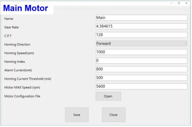
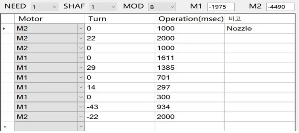
Automatic Transplant Devices ... 84 Figure 3-2. Ratio According to Varying Hair Tansplantation Method ... 86 Figure 3-3. Number of Hair Transplant Patients (as of 2014) ... 87 Figure 3-4. R&D Promotion for Automatic Hair Transplant Device ... 88 Figure 3-5. System Development Diagram ... 91 Figure 3-6. Assembled Needle-transfer Type Automatic Hair Tranplant Device Commercial Prototype ... 96 Figure 3-7. Assembly Diagram ... 97 Figure 3-8. Head Assembly ... 98 Figure 3-9. Needle Magazine Assembly ... 98 Figure 3-10. Main-motor (left) and Sub-motor (right) ... 99 Figure 3-11. Design Changes for Gripper Body ... 100 Figure 3-12. Design Changes for Cam Profile ... 100 Figure 3-13. Design Changes for Gripper ... 101 Figure 3-14. Design Changes for Cam Supplier and Support Fastening Part ... 101 Figure 3-15. Design Changes for Guide Roller ... 102 Figure 3-16. Design Changes for Needle Magazine Bracket ... 102 Figure 3-17. Design Changes for Guide Grip ... 103 Figure 3-18. Design Changes for Head Bracket Suppoter ... 103 Figure 3-19. Cam Supplier and Supporter Connection Clip Design ... 104 Figure 3-20. Parts with Diamond-like Carbon (DLC) coating ... 105 Figure 3-21. Drive Environment ... 105 Figure 3-22. Motor Control Program GUI ... 106 Figure 3-23. Main Motor Configuration ... 108 Figure 3-24. Sub Motor Configuration ... 108 Figure 3-25. Scenario for Main Motor and Sub Motor in Nozzle Mode (B mode) ... 109
36
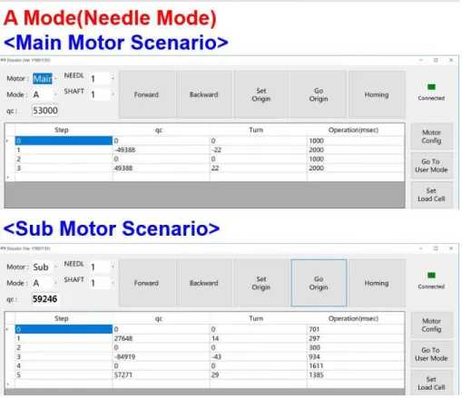
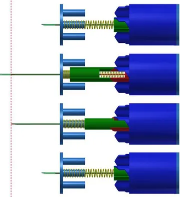
Figure 3-26. Operation of Each Motor in Nozzle Mode ... 109 Figure 3-27. Scenario for Main Motor and Sub Motor in Needle Mode (A mode) ... 110 Figure 3-28. Operation of Each Motor in Needle Mode ... 111 Figure 3-29. Using Automatic Hair Transplanting Machine (left), Using Manual Hair
Transplanting Machine (right) ... 114 Figure 3-30. Operation Test with Pig Skin and Pig Muscle ... 116 Figure 3-31. Driving Environment ... 117 Figure 3-32. Preparation for Driving the Automatic Hair Transplantation test (left)
and Actual Hair Follicle Tranplantation Results (right) ... 117 Figure 3-33. Test Scene of the Needle Moving Forward and Backward ... 118 Figure 3-34. Test Scene of Loading Needle Magazine ... 119 Figure 3-35. Operation Sequence of Existing Hand-held Automatic Hair Transplant
Device ... 120 Figure 3-36. Commercial Device Classification (left) and Bevel Comparative Analysis
(right) ... 121 Figure 3-37. Pressure Load According to Manual Hair Clipper Insertion Pressure and
Insertion Depth ... 122 Figure 3-38. Concept Drawing of Initial Needle Module and Magazine Design ... 123 Figure 3-39. Basic Structure of Retractable Implant Device ... 124 Figure 3-40. Operation Sequence of Retractable Manual Type Implant Device ... 125 Figure 3-41. Four-module Magazine Structure for Automatic Implanting Device ... 126 Figure 3-42. Operation Sequence of 4 Module Magazine for Automatic Implanting Device
... 127 Figure 3-43. Manufactured Retractable Needle Module and Magazine ... 127 Figure 3-44. Initial Needle Module Design ... 128 Figure 3-45. Conceptual Design of Needle Module and Magazine with Spring Removed (1)
... 129 Figure 3-46. Conceptual Design of Needle Module and Magazine without Super-spring (2) ... 129 Figure 3-47. Needle Module with Spring Removed and Magazine 3DP Prototype ... 130 Figure 3-48. Design of Directional Needle Moduel and Magazine... 130 Figure 3-49. 3DP Prototyping of Directional Needle Modules and Magazine (1st) ... 131
37
Figure 3-50. 3DP Prototyping of Directional Needle Module (2nd) ... 132 Figure 3-51. Block Design Diversity of Directional Needle Module ... 132 Figure 3-52. A Perspective View of a Modular Implanting Device ... 133 Figure 3-53. Opening the Front Lid and Advantage the Needle ... 134 Figure 3-54. Magazine Structure ... 135 Figure 3-55. Assembled Needle Module Structure: Prespective View and Cross-sectional
View ... 135 Figure 3-56. Cross-sectional View Showing the Driving of the Needle and the Push Rod
... 136 Figure 3-57. Arrangement of Machined Parts in the Assembly Drawing ... 137 Figure 3-58. 3D Model of a Part from Implanting Device 1 ... 139 Figure 3-59. 3D Model of a Part from Implanting Device 2 ... 139 Figure 3-60. Manufactured Needle Module ... 140 Figure 3-61. Magazine with Six Needle Modules ... 140 Figure 3-62. Finished Prototype Modular Autimatic Hair Implant Device ... 141 Figure 4-1. Conventional Particle-type Bone Graft Material ... 148 Figure 4-2. Patient-specific Bone Grafting (milling type) ... 149 Figure 4-3. Light Scattering Characteristics of Light-cured 3D Printing Ceramic Resin Materials ... 149 Figure 4-4. Ceramics Made with 3D Printing Sold at Argilasys (left) in England and
Unfold (right) in Begium ... 151 Figure 4-5. Bioceramics Implant for Human Transplantation Manufactured by NEXT21
(left) in Japan and Prodways (right) in France ... 152 Figure 4-6. Zirconia parts Manufactured by Lithoz, Austria (left) and Ceramic Parts
Manufactured by ExOne (right), USA ... 152 Figure 4-7. Patent Status of 3D Printing Material [Japan Economy Industry Report,
2014] ... 153 Figure 4-8. Promotion System and Role ... 155 Figure 4-9. Peripheral Hardening Due to Light Scattering of BCP Particles ... 156 Figure 4-10. DLP Based 3D Printing System Complemented by Wiping Blade System .... 157 Figure 4-11. Scale-up Manufacturing Process with BCP Ceramic Particle Separation . 157 Figure 4-12. Calibration Model Results of 30 wt% BCP Ceramic Resin ... 159
38
Figure 4-13. Results of Oral Formability Evaluation of 30 wt% BCP Ceramic Resin .. 159 Figure 4-14. Fracture Image After 1200 ℃ Sintering of the 30 wt% BCP Ceramic .... 160 Figure 4-15. Calibration Model Evaluation Results of 40 wt% BCP Ceramic Resin .... 162 Figure 4-16. Image Before and After Sintering of the Oral Cavity Model of 40 wt% BCP
Ceramic Resin ... 162 Figure 4-17. Fracture Image After Sintering 1200 ℃ for 40 wt% BCP Ceramic ... 163 Figure 4-18. Oral Modeling Image of 50 wt% BCP Ceramiv Resin... 165 Figure 4-19. Image Before and After Sintering of the Oral Model of 50 wt% BCP Ceramic Resin ... 165 Figure 4-20. Fracture Image After Sintering 1200 ℃ for 50 wt% BCP Ceramics ... 166 Figure 4-21. Structure and Role of Wiping Blade ... 167 Figure 4-22. The Blade Body with the Mixing Hole Extended ... 167 Figure 4-23. 3D Printing Operation Using the Improved Blade ... 168 Figure 4-24. A 3D Sculpture Output Using the Improved Blade ... 168 Figure 4-25. Thermal Analysis of Photo-curable Ceramic Resin... 169 Figure 4-26. Sintering Schedule Graph ... 170 Figure 4-27. Crystallinity Analysis After Sintering of BCP Material ... 171 Figure 4-28. Specimen Used for Compressive Strength Evaluation ... 172 Figure 4-29. Graph of Compression Strength Evaluation ... 172 Figure 4-30. DLP-based Medical Ceramic 3D Printer Appearance... 176 Figure 4-31. DLP-based Medical Ceramic 3D Printer Molding Block Projections ... 177 Figure 4-32. DLP-based Medical Ceramic 3D Printer Prototype Block Prototype ... 177 Figure 4-33. DLP-based Medical Ceramic 3D Printer Resin Block Projections ... 178 Figure 4-34. DLP based Medical Ceramic 3D Printer Resin Block Prototype ... 178 Figure 4-35. DLP-based Medical Ceramic 3D Printer Blade System Prototype ... 179 Figure 4-36. Block Diagram of DLP-based Medical Ceramic 3D Printer ... 179 Figure 5-1. Status of Chronic Patients at Home and Abroad ... 188 Figure 5-2. Problems with Long-term Medication ... 189 Figure 5-3. Necessity of Establishing Global Smart Medication Monitoring System .. 190 Figure 5-4. Necessity of Developing Integrated Disease Management System ... 191 Figure 5-5. Limitations of Direct Medication Confirmation ... 192 Figure 5-6. Major Market for Medication Monitoring Technology... 193
39
Figure 5-7. Comparison of Medication Monitoring Devices ... 194 Figure 5-8. Prescription Drug use in Domestic Patients ... 195 Figure 5-9. Joint Research and Development Promotion System ... 197 Figure 5-10. Tuberculosis Integrated Management System Functional Block Diagram .. 199 Figure 5-11. Mobile Medication Monitoring Service 1 ... 200 Figure 5-12. Mobile Medication Monitoring Service 2 ... 201 Figure 5-13. Mobile Medication Monitoring Service 3 ... 201 Figure 5-14. Mobile Medication Monitoring Service 4 ... 202 Figure 5-15. Mobile Medication Monitoring Service 5 ... 202 Figure 5-16. Web-based Medication Monitoring Service 1 ... 203 Figure 5-17. Mobile Medication Monitoring Service 2 ... 203 Figure 5-18. Multimedia Transmission Function and Various Mobile Service Functions 204 Figure 5-19. Summary of Medication Management Dashboard (left) and Monthly Medication Summary (right) ... 205 Figure 5-20. Medication Management Functions and Daily Statistics ... 205 Figure 5-21. A Complete List of Patient ID-based Medication-related Statistics ... 206 Figure 5-22. Statistical Analysis by Sex Ratio and Age - Planned to Be Implemented 206 Figure 5-23. Decision Tree Between DDOT and Traditional DOT ... 207 Figure 5-24. Interview Data for Local Medical Practitioners ... 208 Figure 5-25. Local Agreements to Expand Business ... 210 Figure 5-26. Agreement with Morocco Ministry of Health to Expand Business in Tanger 1
... 211 Figure 5-27. Agreement with Morocco Ministry of Health to Expand Business in Tanger 2
... 211 Figure 5-28. Morocco Ambassador to Korea and Dinner. ... 212 Figure 5-29. Meeting with Chairmen of TTA Regional Meeting to Expand Business Area 213 Figure 5-30. Database Structure ... 214 Figure 5-31. Scenario Flow of Medication Prediction Service ... 215 Figure 5-32. Patient Data Based Drug Prediction System Structure ... 217 Figure 5-33. Neural Network Model Structure for Predicting Adaptive Grouping of
Screening Steps ... 219 Figure 5-34. Reasoning Model Structure for Predicting Adaptive Group Prediction in
40
Screening Step ... 220 Figure 5-35. Reasoning, Neural Network Integration for Screening Stage Medication
Compliance Group Results Medication Compliance Group Judgment Part .... 221 Figure 5-36. Neural Network Model for Predicting Non-medication Risk in Monitoring
Phase ... 222 Figure 5-37. Final Adherence Calculation Model ... 225 Figure 5-38. Tuberculosis Patient Medication Prediction Service Configuration .... 226 Figure 5-39. Medication Prediction System Structure ... 227 Figure 5-40. Message Protocol 1 ... 228 Figure 5-41. Message Protocol 2 ... 228 Figure 5-42. Message Protocol 3 ... 229 Figure 5-43. Message Protocol 4 ... 229 Figure 5-44. Message Protocol 5 ... 230 Figure 6-1. Production, Export and Import Status of Ultrasound Imaging System in
Korea ... 240 Figure 6-2. Block Diagram of Portable Wireless Ultrasound Imaging System ... 242 Figure 6-3. Name and Use of Array Type Ultrasonic Transducer for Image Diagnosis . 244 Figure 6-4. Array Type Ultrasonic Transducer ... 244 Figure 6-5. Structure of Developed Array Type Ultrasonic Transducer ... 245 Figure 6-6. Ultrasonic Transducer Manufactured ... 246 Figure 6-7. Block Diagram of Developed Ultrasonic Front-end Module ... 248 Figure 6-8. Ultrasonic Front-end Module and Transducer Assembly Photo ... 248 Figure 6-9. Digital Beamformer Example ... 250 Figure 6-10. Ultrasonic System Control and Wireless Communication Module Block
Diagram ... 250 Figure 6-11. Example of a GMP Line and Corresponding Device ... 251 Figure 6-12. GMP Certificate for Portable Wireless Ultrasonic Diagnostic System
Production ... 252 Figure 6-13. System Diagram ... 253 Figure 6-14. Configuration Diagram of Software for Smart Device ... 254 Figure 6-15. Brightness and Contrast Adjustment Results ... 255 Figure 6-16. Histogram Equalization Results ... 255
41
Figure 7-1. Sensor System Configuration and Concept Diagram for Pill Counting .... 262 Figure 7-2. Propulsion System and Role ... 268 Figure 7-3. Minimum Sensor Spacing for Sensor Module Development ... 270 Figure 7-4. Review of Lens Application for 1:N Sensor Configuration ... 271 Figure 7-5. Manufacture of IR Emitter Sensor PCB ... 273 Figure 7-6. IR Detector PCB Making ... 273 Figure 7-7. Jig Making ... 273 Figure 7-8. Mounting the Sensor Board ... 274 Figure 7-9. Main PCB Making Drawings ... 275 Figure 7-10. IR Emitter PCB Making Drawings. ... 276 Figure 7-11. IR Detector PCB Making Drawings ... 276 Figure 7-12. PCB Assembly ... 276 Figure 7-13. Checking the Transmission Data ... 277 Figure 7-14. Prototype of IR LED Type Module ... 277 Figure 7-15. Laser LED Type Module Prototype ... 278 Figure 7-16. Design for Module Section ... 278 Figure 7-17. Hopper Section Design ... 279 Figure 7-18. Lens Design ... 279 Figure 7-19. Loaded Firmware ... 280 Figure 7-20. Sensor Module Mockup Assembly ... 280 Figure 7-21. Assembly of the Hopper ... 281 Figure 7-22. Final Assembly of the Prototype ... 281 Figure 7-23. Initial Data Acquisition ... 282 Figure 7-24. Data Transformation and Identification of Tablet Shape ... 283 Figure 7-25. Resetting the Pills Area ... 284 Figure 7-26. Pill Start Time Reference Counting Algorithm ... 285 Figure 7-27. Design and Conceptual Diagram of Real-time Coefficient Algorithm .... 286 Figure 7-28. Algorithm Implementation (C ++) ... 286 Figure 7-29. Additional Data Acquisition (2) ... 287 Figure 7-30. Additional Data Acquisition (5) ... 287 Figure 7-31. Additional Data Acquisition (10) ... 288 Figure 7-32. Checking the Result of Algorithm Execution ... 289
43
목 차
제 1 장 서 론 ... 59 제1절 연구개발 목표 및 연구내용 ... 59 1. 연구개발 목표 ... 59 2. 연구개발 필요성 ... 60 3. 당해연도 연구내용 ... 62 제2절 연구 수행방법 및 보고서 체계 ... 65 1. 연구개발 추진체계 및 수행방법 ... 65 2. 보고서 체계 ... 67 제 2 장 연구 수행결과 ... 71 제1절 당해 연도 연구성과 실적 ... 71 1. 연구성과 개요 ... 71 2. 연구성과 실적 ... 73 제 3 장 모발이식시스템 실용화 및 차세대 모발이식장치 기반 기술 개발 ... 83 제1절 개발 개요 ... 83 1. 목적 ... 83 2. 필요성 ... 83 3. 연구개발 동향 ... 85 4. 국내 모발이식장치 현황 ... 85 5. 추진체계 및 수행방법 ... 88 6. 개발 범위 ... 89 제2절 모발이식시스템 실용화 기술 개발 ... 90 1. 일반 사항 ... 90 2. 바늘이송형 자동식모기 상용시제품 요구사항 ... 91 3. 바늘이송형 자동식모기 상용시제품 제작 ... 96 4. 누드마우스를 이용한 동물시험 및 동물 피부 테스트 ... 111 5. 상용시제품의 품목허가를 위한 안정성/신뢰성 평가 ... 117 제3절 차세대 모발이식장치 기반 기술 개발 ... 12044 1. 차세대 모발이식장치 최소 유닛 설계... 120 2. 차세대 모발이식장치 최소 유닛 시제품 제작 ... 133 제4절 기대효과 및 향후 계획 ... 143 1. 연구개발의 우수성 ... 143 2. 기대효과 ... 143 3. 향후 계획 ... 144 제 4 장 환자맞춤형/생체이식형 세라믹 3D 프린터 및 소재 실용화 기술 개발 .. 147 제1절 개발 개요 ... 147 1. 목적 ... 147 2. 필요성 ... 147 3. 연구개발 동향 ... 149 4. 추진체계 및 수행방법 ... 154 5. 개발 범위 ... 155 제2절 세라믹 소재 DLP 기반 3D 프린팅을 위한 광경화성 레진 소재 기술 개발 ... 156 1. DLP 기반 3D 프린팅을 위한 시스템 사전 검토 ... 156 2. 세라믹 함량별 3D 프린팅 조건 도출 및 조형성 평가 ... 158 3. 3D 프린팅된 골이식재 열 분석 및 물리적 특성 평가 ... 169 제3절 DLP 기반 의료옹 세라믹 3D 프린터 HW/SW 설계 및 프로토 타입 개발 ... 174 1. DLP 기반 의료용 3D 프린터 HW 요구사항 ... 174 2. DLP 기반 의료용 3D 프린터 HW 설계 및 구현 ... 175 제4절 기대효과 및 향후 계획 ... 180 1. 연구개발의 우수성 ... 180 2. 기대효과 ... 181 3. 향후 계획 ... 181 제 5 장 복약 모니터링 서비스와 연동 가능한 질병관리 통합 시스템 개발 ... 187 제1절 개발 개요 ... 187
45 1. 목적 ... 187 2. 필요성 ... 188 3. 연구개발 동향 ... 191 4. 추진체계 및 수행방법 ... 197 5. 개발 범위 ... 198 제2절 복약 모니터링 서비스와 연동 가능한 질병관리 통합 시스템 ... 199 1. 2 세대 실시간 결핵환자 복약 시스템 서비스 ... 199 2. 2 세대 실시간 결핵 환자 복약 예측 서비스를 위한 설계 ... 214 3. 2 세대 실시간 결핵 환자 복약 예측 서비스 개발 ... 225 제3절 기대효과 및 향후 계획 ... 231 1. 연구개발의 우수성 ... 231 2. 기대효과 ... 232 3. 향후 계획 ... 233 제 6 장 휴대용 무선 초음파 영상 진단 시스템 개발... 237 제1절 개발 개요 ... 237 1. 목적 ... 237 2. 필요성 ... 238 3. 연구개발 동향 ... 238 4. 추진체계 및 수행방법 ... 241 5. 개발 범위 ... 241 제2절 휴대용 무선 초음파 영상 진단 하드웨어 개발 ... 242 1. 128 엘리멘트 배열형 초음파 트랜스듀서 ... 242 2. 초음파 Front-end 모듈 ... 247 3. 초음파 신호처리 Preprocessor ... 249 4. 초음파시스템 컨트롤 및 무선통신 모듈 개발 ... 250 5. GMP 인증 ... 251 제3절 휴대용 무선 초음파 신호처리 기술 개발... 253 1. 시스템 구성 ... 253 2. 초음파 신호처리 기술 ... 254
46 제4절 기대효과 및 향후 계획 ... 256 1. 연구개발의 우수성 ... 256 2. 기대효과 ... 257 3. 향후 계획 ... 257 제 7 장 조제 자동화 장비 적용을 위한 정제약품 계수용 센서 모듈 개발 ... 261 제1절 개발 개요 ... 261 1. 목적 ... 261 2. 필요성 ... 262 3. 연구개발 동향 ... 263 4. 추진체계 ... 268 5. 개발 범위 ... 268 제2절 정제약품 계수용 센서 모듈 하드웨어 개발 ... 270 1. 정제약품 계수용 센서 모듈 시제품 (HW) 제작 ... 270 제3절 정제약품 계수용 센서 모듈 소프트웨어 개발 ... 282 1. 정제약품 계수용 알고리즘 (SW) 개발... 282 제4절 기대효과 및 향후 계획 ... 290 1. 연구개발의 우수성 ... 290 2. 연구결과의 기대효과 및 활용 가능성... 291 3. 향후 계획 ... 292 제 8 장 결론 ... 297
47
표 목차
표 2-1. 기술개발 성과지표(1 차년도) ... 71 표 2-2. 연구산출물 성과지표(1 차년도) ... 72 표 2-3. 모발이식시스템 실용화 및 차세대 모발이식장치 기반 기술 개발 연구개발 결과 . 73 표 2-4. 환자맞춤형/생체이식형 세라믹 3D 프린터 및 소재 실용화 기술 개발 연구개발 결과 ... 74 표 2-5. 복약 모니터링 서비스와 연동 가능한 질병관리 통합 시스템 개발 연구개발 결과 75 표 2-6. 휴대용 무선 초음파 영상 진단 시스템 개발 연구개발 결과... 77 표 2-7. 조제 자동화 장비 적용을 위한 정제약품 계수용 센서 모듈 개발 연구개발 결과 . 78 표 2-8. 기술개발 성과지표 달성실적 (2017 년도) ... 79 표 2-9. 연구산출물 성과지표 달성실적 (2017 년도) ... 79 표 3-1. 당해 연도 연구개발 목표 및 결과 ... 84 표 3-2. 모발이식 환자 수에 따른 시장 규모(2014 년 기준) ... 87 표 3-3. 사용자 기능 요구사항 ... 92 표 3-4. 사용자 인터페이스 요구사항 ... 93 표 3-5. 시스템 기능 요구사항 ... 94 표 3-6. 시스템 인터페이스 요구사항 ... 95 표 3-7. 시스템 성능 요구사항 ... 95 표 3-8. 모터 제어 프로그램 GUI 사용방법 ... 106 표 3-9. 동물실험 개요 ... 111 표 3-10. 모낭 이식을 위해 입력된 두 모터의 동작 시퀀스 ... 113 표 3-11. 모낭 이식률 평가 ... 119 표 3-12. 사용자 요구사항 ... 122 표 3-13. 가공 부품의 번호 및 품명 ... 138 표 4-1. ASTM F7292-12a 및 ISO TC261 의 3D 프린팅 방식 분류 ... 150 표 4-2. 세라믹 소재의 3D 프린팅 기술 적용 예 ... 151 표 4-3. 세라믹 소재의 3D 프린팅 특허 ... 153 표 4-4. 30 wt% BCP 세라믹 레진 소재의 조성표 ... 158 표 4-5. 40 wt% BCP 세라믹 레진 소재의 조성표 ... 161 표 4-6. 50 wt% BCP 세라믹 레진 소재의 조성표 ... 16348 표 4-7. 50 wt% BCP 세라믹 레진 소재의 압축 강도 평가 결과 ... 173 표 4-8. DLP 기반 의료용 3D 프린터 HW 요구사항 ... 174 표 4-9. 상용화 추진전략 및 일정 ... 183 표 5-1. 국내 복약지원 디바이스 제품 현황 ... 196 표 5-2. 국내 복약관리 앱 현황 ... 196 표 5-3. 복약 순응율 예측을 위한 수집 정보 및 가중치 ... 209 표 5-4. 복약 예측 서비스 시나리오 별 상세 진행 내용 ... 216 표 5-5. 복약 예측 서비스 모델에 사용되는 데이터 및 인코딩 1 ... 218 표 5-6. 복약 예측 서비스 모델에 사용되는 데이터 및 인코딩 2 ... 223 표 5-7. 모니터링 단계에 사용되는 특징 및 추출방법 ... 224 표 5-8. 메시지 프로토콜 포맷 ... 227 표 6-1. 초음파 변환기 사양 ... 246 표 7-1. 국내 주요 기업 현황 ... 263 표 7-2. 국내 제품 비교 ... 264 표 7-3. 해외 주요 기업 현황 ... 265 표 7-4. 해외 제품 비교 ... 266 표 7-5. 관련 특허 ... 267 표 7-6. 연구 수행 방법 (1 차년도) ... 269 표 7-7. 상용화 추진 전략 ... 293
49
그림 목차
그림 1-1. 연구개발 추진체계(1) ... 65 그림 1-2. 연구개발 추진체계(2) ... 66 그림 3-1. 자동 모발이식장치의 개발 배경: 기존 식모기 시술의 문제점 ... 84 그림 3-2. 모발이식 방식에 따른 비율 ... 86 그림 3-3. 모발이식 환자 수(2014 년 기준) ... 87 그림 3-4. 자동 식모기 관련 연구개발 추진체계 ... 88 그림 3-5. 개발시스템 구성도 ... 91 그림 3-6. 바늘이송형 자동식모기 상용시제품 총 어셈블리 ... 96 그림 3-7. 조립도 ... 97 그림 3-8. 헤드 어셈블리 (Head assembly) ... 98 그림 3-9. 바늘 탄창 어셈블리 (Needle magazine assembly) ... 98 그림 3-10. 메인 모터 (Main-motor, 좌) 및 서브 모터 (Sub-motor, 우) ... 99 그림 3-11. 그리퍼 몸체 (Gripper body) 설계 변경 도면 ... 100 그림 3-12. 캠 프로파일 (Cam profile) 설계 변경 도면 ... 100 그림 3-13. 그리퍼 (Gripper) 설계 변경 도면 ... 101 그림 3-14. 캠 서플라이어 및 서포터 체결부 구조 변경 도면 ... 101 그림 3-15. 가이드 롤러 (Guide roller) 도면 ... 102 그림 3-16. 바늘 탄창 브라켓 (Needle Magazine Bracket) 설계 변경 도면 ... 102 그림 3-17. 가이드 그립 (Guide grip) 설계 변경 도면 ... 103 그림 3-18. 헤드 브라켓 서포터 (Head bracket supporter) 설계 변경 도면 ... 103 그림 3-19. 캠 서플라이어 및 서포터 (Cam supplier, supporter) 연결부 클립 (Clip) 도면... 104 그림 3-20. DLC (Diamond-like Carbon) 코팅 적용 부품 ... 105 그림 3-21. 구동 환경 ... 105 그림 3-22. 모터 제어 프로그램 GUI ... 106 그림 3-23. 메인 모터의 환경 설정 ... 108 그림 3-24. 서브 모터의 환경 설정 ... 108 그림 3-25. 노즐 모드 (B mode)의 메인 모터 및 서브 모터의 시나리오 ... 109 그림 3-26. 노즐 모드의 각 모터 연계 동작 ... 109
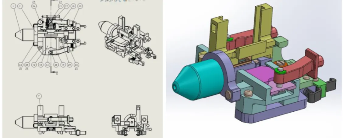
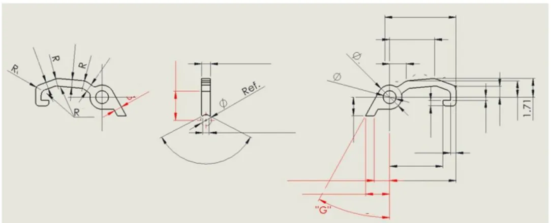
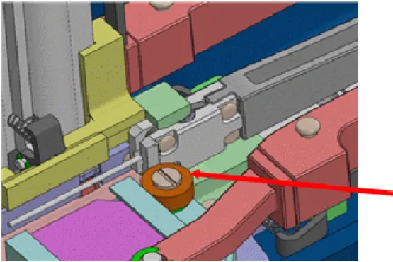
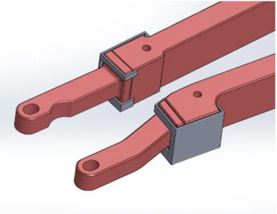
50 그림 3-27. 바늘 모드 (A mode)의 메인 모터 및 서브 모터의 시나리오 ... 110 그림 3-28. 바늘 모드의 각 모터 연계 동작 ... 111 그림 3-29. 자동모발이식기 사용 식모(좌), 수동모발이식기 사용 식모(우) ... 114 그림 3-30. 돼지 피부 및 근육을 이용한 작동 테스트 ... 116 그림 3-31. 구동 환경 ... 117 그림 3-32. 자동모발이식기 구동 시험 준비 모습(좌) 및 실제 모낭 이식 결과(우) ... 117 그림 3-33. 바늘 전후진 테스트 장면 ... 118 그림 3-34. 바늘 탄창의 바늘 공급 테스트 장면 ... 119 그림 3-35. 기존 수동 식모기의 동작 순서 ... 120 그림 3-36. 상용기기 분류(좌), 베벨 비교 분석(우) ... 121 그림 3-37. 수동모발이식기 삽입 압력 및 삽입 깊이에 따른 압력하중 ... 122 그림 3-38. 초기 바늘 모듈 및 매거진 설계 개념도 ... 123 그림 3-39. Retractable 식모기의 기본 구조 ... 124 그림 3-40. Retractable 수동 식모기의 동작 순서 ... 125 그림 3-41. 자동 식모기용 4 모듈 매거진 구조 ... 126 그림 3-42. 자동 식모기용 4 모듈 매거진 동작 순서 ... 127 그림 3-43. 제작된 retractable 바늘모듈과 매거진 ... 127 그림 3-44. 초기 바늘모듈 설계 ... 128 그림 3-45. 스프링을 제거한 바늘모듈 및 매거진 개념설계 (1) ... 129 그림 3-46. 초 스프링을 제거한 바늘모듈 및 매거진 개념설계 (2)... 129 그림 3-47. 스프링을 제거한 바늘모듈 및 매거진 3DP 시제품 ... 130 그림 3-48. 방향성을 가지는 바늘모듈 및 매거진의 설계 ... 130 그림 3-49. 방향성을 가지는 바늘모듈 및 매거진의 3DP 시제품 제작 (1 차) ... 131 그림 3-50. 방향성을 가지는 바늘모듈의 3DP 시제품 제작 (2 차) ... 132 그림 3-51. 방향성을 가지는 바늘모듈의 블록 설계 다양화 ... 132 그림 3-52. 설계된 모듈형 식모기의 사시도 ... 133 그림 3-53. 전면 리드의 개방과 바늘의 전진 ... 134 그림 3-54. 매거진 구조 ... 135 그림 3-55. 조립된 바늘모듈 구조: 사시도 및 단면도 ... 135 그림 3-56. 바늘과 푸쉬로드의 구동을 보여주는 단면도 ... 136 그림 3-57. 조립도에서 가공 부품의 배치 ... 137 그림 3-58. 식모기 전면부의 일부 부품 3D 모델 1 ... 139
51 그림 3-59. 식모기 전면부의 일부 부품 3D 모델 2 ... 139 그림 3-60. 제작된 바늘모듈 ... 140 그림 3-61. 6 개의 바늘모듈이 조립된 매거진 ... 140 그림 3-62. 완성된 모듈형 자동 모발이식장치 시제품 ... 141 그림 4-1. 기존 사용되는 입자형 골이식재 ... 148 그림 4-2. 환자 맞춤형 골이식재 (milling type) ... 149 그림 4-3. 광중합형 3D 프린팅 세라믹 레진 소재의 광산란 특성 ... 149 그림 4-4. 영국의 Argilasys 사(좌)와 벨기에 Unfold 사(우)에서 판매중인 3D 프린팅으로 제작된 생활 도자기 ... 151 그림 4-5. 일본 NEXT21 사(좌)와 프랑스 Prodways 사(우)에서 판매중인 3D 프린팅으로 제작된 인체 이식용 바이오 세라믹스 임플란트 ... 152 그림 4-6. 오스트리아 Lithoz 사(좌)에서 제작한 지르코니아 부품 및 미국 ExOne 사(우)에서 제작한 세라믹 부품 ... 152 그림 4-7. 3D 프린팅 소재 특허 현황 [일본 경제산업체 보고서, 2014] ... 153 그림 4-8. 추진체계 및 역할 ... 155 그림 4-9. BCP 입자의 광산란으로 인한 주변부 경화 발생 ... 156 그림 4-10. Wiping blade 시스템이 보완된 DLP 기반 3D 프린팅 시스템 ... 157 그림 4-11. BCP 세라믹 입자 분리가 가능한 Scale-up 된 제조 공정... 157 그림 4-12. 30 wt% BCP 세라믹 레진의 기본 Calibration model 평가 결과 ... 159 그림 4-13. 30 wt% BCP 세라믹 레진의 구강 모형 조형성 평가 결과... 159 그림 4-14. 30 wt% BCP 세라믹 함유 조형물의 1200℃ 소결 후 파단면 이미지 ... 160 그림 4-15. 40 wt% BCP 세라믹 레진의 기본 Calibration model 평가 결과 ... 162 그림 4-16. 40 wt% BCP 세라믹 레진의 구강 모형의 소결 전/후 이미지 ... 162 그림 4-17. 40 wt% BCP 세라믹 함유 조형물의 1200℃ 소결 후 파단면 이미지 ... 163 그림 4-18. 50 wt% BCP 세라믹 레진의 구강 모형 조형 이미지 ... 165 그림 4-19. 50 wt% BCP 세라믹 레진의 구강 모형의 소결 전/후 이미지 ... 165 그림 4-20. 50 wt% BCP 세라믹 함유 조형물의 1200℃ 소결 후 파단면 이미지 ... 166 그림 4-21. Wiping blade 의 구조 및 역할 ... 167 그림 4-22. Mixing hole 을 확장시킨 blade body ... 167 그림 4-23. 개선된 Blade 를 활용한 3D 프린팅 동작 모습 ... 168 그림 4-24. 개선된 Blade 를 활용해 출력한 3 차원 조형물 ... 168 그림 4-25. 광경화성 세라믹 레진의 열적 특성 분석 ... 169
52 그림 4-26. 소결 스케쥴 그래프 ... 170 그림 4-27. BCP 소재의 소결 후 결정화도 분석 ... 171 그림 4-28. 압축 강도 평가에 사용된 시편 ... 172 그림 4-29. 압축 강도 평가 그래프 ... 172 그림 4-30. DLP 기반 의료용 세라믹 3D 프린터 외관 ... 176 그림 4-31. DLP 기반 의료용 세라믹 3D 프린터 조형 블록 예상도... 177 그림 4-32. DLP 기반 의료용 세라믹 3D 프린터 조형 블록 시제품... 177 그림 4-33. DLP 기반 의료용 세라믹 3D 프린터 레진 블록 예상도... 178 그림 4-34. DLP 기반 의료용 세라믹 3D 프린터 레진 블록 시제품... 178 그림 4-35. DLP 기반 의료용 세라믹 3D 프린터 Blade system 시제품 ... 179 그림 4-36. DLP 기반 의료용 세라믹 3D 프린터 전자 부품 블록 예상도 ... 179 그림 5-1. 국내외 만성질환자 현황 ... 188 그림 5-2. 장기 투약에 따른 문제점 ... 189 그림 5-3. 글로벌 스마트 복약 모니터링 시스템 구축의 필요성 ... 190 그림 5-4. 질병 통합 관리 시스템 개발의 필요성 ... 191 그림 5-5. 직접 복약 확인의 한계 ... 192 그림 5-6. 복약 모니터링 기술 주요 시장 ... 193 그림 5-7. 복약 모니터링 디바이스 비교 ... 194 그림 5-8. 국내 환자의 처방약 복용 실태 ... 195 그림 5-9. 공동 연구 개발 추진 체계 ... 197 그림 5-10. 결핵 (질병) 통합 관리 시스템 기능 블록 구성도 ... 199 그림 5-11. 모바일 복약 모니터링 서비스 1 ... 200 그림 5-12. 모바일 복약 모니터링 서비스 2 ... 201 그림 5-13. 모바일 복약 모니터링 서비스 3 ... 201 그림 5-14. 모바일 복약 모니터링 서비스 4 ... 202 그림 5-15. 모바일 복약 모니터링 서비스 5 ... 202 그림 5-16. 웹기반 복약 모니터링 서비스 1 ... 203 그림 5-17. 모바일 복약 모니터링 서비스 2 ... 203 그림 5-18. 멀티미디어 전송 기능 및 다양한 모바일 서비스 기능 – 구현 예정 ... 204 그림 5-19. 복약 관리 대시보드(좌) 및 월별 복약 현황 요약 기능 (우) ... 205 그림 5-20. 복약 관리 기능 및 일별 통계 ... 205 그림 5-21. 환자 ID 기반 복약 관련 통계 전체 리스트 ... 206
53 그림 5-22. 성비 및 연령별 통계 분석 – 구현 예정 ... 206 그림 5-23. DDOT 와 전통적 DOT 사이의 의사결정트리 ... 207 그림 5-24. 현지 의료인 대상 인터뷰 자료 ... 208 그림 5-25. 탕줘 사업 확대를 위한 현지 협약 ... 210 그림 5-26. 탕줘 지역 사업 확대를 위한 모로코 보건부와 협약식 1... 211 그림 5-27. 탕줘 지역 사업 확대를 위한 모로코 보건부와 협약식 2... 211 그림 5-28. 모로코 주한대사 면담 및 만찬 ... 212 그림 5-29. 사업 지역 확대를 위한 TTA 지방회의 의장 등과의 미팅... 213 그림 5-30. 데이터베이스 구조 ... 214 그림 5-31. 복약 예측 서비스 시나리오 흐름 ... 215 그림 5-32. 환자 데이터 기반 복약 예측 시스템 구조 ... 217 그림 5-33. 스크리닝 단계 복약 순응 그룹 예측을 위한 Neural Network 모델 구조 ... 219 그림 5-34. 스크리닝 단계 복약 순응 그룹 예측을 위한 Reasoning 모델 구조 ... 220 그림 5-35. 스크리닝 단계 복약 순응 그룹 결과를 위한 Reasoning, Neural Network 통합
복약 순응 그룹 판단부 ... 221 그림 5-36. 모니터링 단계 미복약 위험도를 예측하기 위한 Neural Network 모델 ... 222 그림 5-37. 최종 복약율 계산 모델 구조 ... 225 그림 5-38. 결핵 환자 복약 예측 서비스 구성 ... 226 그림 5-39. 복약 예측 시스템 구조 ... 227 그림 5-40. 메시지 프로토콜 1 ... 228 그림 5-41. 메시지 프로토콜 2 ... 228 그림 5-42. 메시지 프로토콜 3 ... 229 그림 5-43. 메시지 프로토콜 4 ... 229 그림 5-44. 메시지 프로토콜 5 ... 230 그림 6-1. 국내 초음파영상진단장치 생산 및 수출·수입 현황 ... 240 그림 6-2. 휴대용 무선 초음파 영상진단시스템의 블록 다이어그램... 242 그림 6-3. 영상 진단용 배열형 초음파 변환기의 명칭과 용도 ... 244 그림 6-4. 배열형 초음파 변환기 ... 244 그림 6-5. 개발된 배열형 초음파 변환기의 구조 ... 245 그림 6-6. 제작된 초음파 변환기 ... 246 그림 6-7. 개발된 초음파 Front-End 모듈의 블록 다이어그램 ... 248 그림 6-8. 개발된 초음파 Front-End 모듈과 트랜스듀서 조립 사진... 248
54 그림 6-9. 디지털 빔포머 예시 ... 250 그림 6-10. 초음파시스템 컨트롤 및 무선통신 모듈 블록 다이어그램... 250 그림 6-11. GMP 품목군 및 해당 기기예시 ... 251 그림 6-12. 휴대용 무선 초음파 진단 시스템 생산을 위한 GMP 인증서 ... 252 그림 6-13. 시스템 구성도 ... 253 그림 6-14. 스마트 기기용 소프트웨어의 구성도 ... 254 그림 6-15. Brightness 및 Contrast 조절 결과 ... 255 그림 6-16. Histogram equalization 결과 ... 255 그림 7-1. 정제약품 계수용 센서 시스템 구성 및 개념도 ... 262 그림 7-2. 추진체계 및 역할 ... 268 그림 7-3. 센서 모듈 개발을 위한 센서 최소 간격 ... 270 그림 7-4. 1:N 센서 구성을 위한 렌즈 적용 검토 ... 271 그림 7-5. IR Emitter Sensor PCB 제작 ... 273 그림 7-6. IR Detector PCB 제작 ... 273 그림 7-7. 지그 제작 ... 273 그림 7-8. 센서 보드 장착 ... 274 그림 7-9. 메인 PCB 제작 도면 ... 275 그림 7-10. IR Emitter PCB 제작 도면 ... 276 그림 7-11. IR Detector PCB 제작 도면 ... 276 그림 7-12. PCB 조립 ... 276 그림 7-13. 전송 데이터 확인 ... 277 그림 7-14. IR LED 형 모듈 시제품 ... 277 그림 7-15. Laser LED 형 모듈 시제품 ... 278 그림 7-16. 모듈 주변 기구부 설계 ... 278 그림 7-17. 호퍼부 설계 ... 279 그림 7-18. 렌즈 설계 ... 279 그림 7-19. 펌웨어 탑재 ... 280 그림 7-20. 센서 모듈 목업 조립 ... 280 그림 7-21. 호퍼부 조립 ... 281 그림 7-22. 시제품 최종 조립 ... 281 그림 7-23. 초기 데이터 획득 ... 282 그림 7-24. 데이터 변환 및 알약 형상 확인 ... 283
55 그림 7-25. 알약 영역 재설정 ... 284 그림 7-26. 알약 시작 시점 기준 계수 알고리즘 ... 285 그림 7-27. 실시간 계수 알고리즘 설계 및 개념도 ... 286 그림 7-28. 알고리즘 구현 (C++) ... 286 그림 7-29. 데이터 추가 획득 (2 개) ... 287 그림 7-30. 데이터 추가 획득 (5 개) ... 287 그림 7-31. 데이터 추가 획득 (10 개) ... 288 그림 7-32. 알고리즘 수행 결과 확인 ... 289
제 1 장
59
제 1 장 서 론
제1절 연구개발 목표 및 연구내용
1. 연구개발 목표
본 사업의 목적은 대경권 지역기반 의료 ICT 융복합 기술 개발을 통한 지역 의료 기기 신산업 창출 및 개방형 R&BD 를 통한 중소기업 기술 경쟁력을 강화하는 것이 다. 이에 따른 사업의 목표는 다음과 같다. □ 지역특화/지역수요 반영 스마트 의료기기 핵심기술 개발 □ 기업체 밀착형 의료기기 실용화 Open R&BD □ 지역 유관기관 연계 지역 의료산업 발전정책 수립 및 신사업 발굴 세부 목표는 다음과 같다. □ 지역특화/지역수요 반영 스마트 의료기기 핵심기술 개발 지역특화/시장창출형 스마트 의료기기 실용화 핵심기술 개발 · 지역 특화분야와 및 병원 수요 기반으로 연구소-병원-기업 협력형 ICT 융복합 의료기기 기술/제품 공동 기획 · 임상 환경을 고려한 ICT 융복합 의료기기 상세 설계 및 시제품 개발 · 모발이식시스템 실용화 및 차세대 모발이식장치 기반 기술 개발 · 환자맞춤형/생체이식형 세라믹 3D 프린터 및 소재 실용화 기술 개발 의료현장/시장주도형 의료기기 실용화 제품 개발 · 지역 기업체 대상 기술수요조사 및 맞춤형 공동 개발 제품 선정60 · 시장 환경 및 경쟁 제품 분석을 통한 의료기기 상세 설계 및 시제품 개발 · 국제규격(IEC 60601 3rd Edition) 기준 안정성/유효성 시험 평가 및 기술지원 · 복약 모니터링 서비스와 연동 가능한 질병관리 통합 시스템 개발 · 휴대용 무선 초음파 영상 진단 시스템 개발 · 조제 자동화 장비 적용을 위한 정제약품 계수용 센서 모듈 개발 □ 기업체 밀착형 의료기기 실용화 Open R&BD 병원 연계 ICT 융복합 의료 제품/서비스 수요조사 개방형 산ㆍ학ㆍ연ㆍ관 기술혁신 주체 및 전문가 운영위원회 구축․운영 중소․중견기업의 조기 실용화/사업화를 위한 기술지원 □ 지역 유관기관 연계 지역 의료산업 발전정책 수립 및 신사업 발굴 대구ㆍ경북 지자체 연계 지역 의료산업 발전정책 수립 기여 대구경북첨단의료산업진흥재단, 구미전자정보기술원 등 지역 유관기관과의 협력을 통한 신사업 발굴 djckv
2. 연구개발 필요성
본 연구의 필요성은 기술 및 산업 측면으로 나누어 볼 수 있다. 먼저 기술 측면 에서의 본 연구개발의 필요성은 다음과 같다.□ ETRI 의료 ICT 원천기술을 지역 의료 ICT 산업에 접목하여 지역 의료 ICT 산업 활성화
□ ETRI↔지역 의료관련 중소기업 상생협력을 통해 취약한 중소기업의 기술경쟁력 제고
□ ETRI 기술사업화 성공률 향상→ETRI R&D 성과확산→중소기업 R&D 지원 강화 등 선순환 고리 정착
61 □ 글로벌 상용화 기술 개발 및 전수로 중소기업의 해외시장 진출을 위한 경쟁력 있는 세계화 기술 확보 다음으로, 산업 측면에서의 본 연구개발의 필요성은 다음과 같다. □ 지역의 의료관련 중소기업 동반성장의 핵심 조력자로서 중소기업 지속 성장 및 활력 회복의 기틀 마련 □ 의료기기 개발 관련 지역 산업체, 출연(연), 첨복단지, 대학병원 협력관계 유도 및 의료기기 제품 상용화 능력 제고 □ 모발이식로봇 등 지역 특화 의료기기 개발을 통하여 지역 특화 관광 의료 산업 발전에 기여 □ 지역 의료기기 산업 매출액 증대 기대 및 고용창출에 기여 □ 지역 전략산업과 연계된 의료기기 산업체 수요기반 IT 융합 의료기기 상용제품 개발로 기업 창업 및 유치, 연구지원을 촉진함으로써 지역 경제 활성화 □ 산ㆍ학ㆍ연ㆍ관 기술정보 교류/협력 네트워크 활동을 통한 지역 R&D 역량 강화 □ 지역 병원, 보건소, 약국 및 가정을 연계한 새로운 형태의 서비스 창출 및 서비스 생태계 구축 □ 글로벌 모델 발굴 및 현지화를 통한 지역 중소기업의 해외시장 진출의 토대 마련