09-S-235
대한설비공학회 2009 하계학술발표대회 논문집 pp. 1332 ~ 1336공조장치내의 직렬-직렬 대향류 냉각기에서 최적 변수
웬 민 푸*, 뷔 옥 훙**, 이 근 식†
울산대학교 대학원*, 호치민공대 기계공학과**, 울산대학교 기계자동차공학부†
The optimal parameters in series-series counterflow chillers system
within air conditioning
Nguyen Minh Phu*, Bui Ngoc Hung**, and Geun Sik Lee†
ABSTRACT: If water-chillers are arranged in series-series counterflow, compressor lift of each chiller will be decreased in comparison with water-chillers in parallel. That means that compressor power of the chillers in series will be lower than that of chillers in parallel. However, the pressure drop of the water flow through the chillers in series will increase, and thus increase the power of water pumps. This disadvantage will be made good by increasing the temperature difference of water flow through evaporator and condenser, but the water flow rates will decrease. This paper explores the optimal parameters in system of series-series counterflow for central chilled water plants such as the leaving chilled water temperature, the leaving condenser water temperature, condenser water flow rate and number of chillers in series.
Key words: Series-series chillers, Low-flow system, Energy saving, Air conditioning
†Corresponding author
Tel.: +82-52-259-2135; fax: +82-52-259-1680 E-mail address: [email protected] 1. Introduction
In recent years, more and more attentions are paid on energy savings throughout the world. In general developing trend of the world and the human demand, air conditioning systems are being installed popularly. Air conditioning systems consume considerable electric power in commercial buildings, about 40% of total consumed electricity. So, there are many ways to save energy and reduce power demand of air-conditioning systems, such as
ice storage system, absorption
refrigeration/heat pump system and refrigeration/heat pump system driven by gas engine or gas turbine, with a combined cold, heat and power system, etc. Among the ways to save energy, series-series counterflow chillers arrangement is also being studied and applied in recent periods.
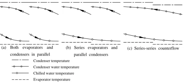
In conventional configuration, chillers are usually arranged in parallel. The chillers lined up in parallel must create the coldest water required for the entire system while rejecting heat to the warmest condensing temperature (Fig. 1a.). If evaporators and condensers are arranged in series and parallel, respectively (Fig. 1b.), the chilled water temperature exiting the upstream chiller is always warmer than
Condenser temperature Condenser water temperature Chilled water temperature Evaporator temperature
(a) Both evaporators and condensers in parallel
(c) Series-series counterflow (b) Series evaporators and
parallel condensers
Fig. 1 Temperature variations of the system with two chillers the water temperature of the downstream
chiller. Therefore the compressor lift of upstream chiller will reduce. Similarly, if both evaporators and condensers are arranged in series but if the chilled and condenser water flow directions are counter (Fig. 1c.), the chilled water temperature exiting the upstream chiller is higher than the water temperature of the downstream chiller but the condenser water temperature exiting the downstream chiller is always lower than the water temperature of the upstream chiller. The lift of each compressor is nearly the same.
On the contrary, in series chillers system, all the system flows go through both chillers. As a result, the water pressure drops through the evaporators are additive. Yet, the savings in chiller (compressor) power offsets this penalty. Otherwise, to minimize the penalty as much as possible, the temperature difference across series chillers system is increased. Then the water flow rate is reduced.
Moreover, with lower flow rates, piping requirements to delivery the same cooling capacity are smaller, hence reducing the installed costs of low flow systems. If pipe sizes are reduced, the resulting pump power consumption for a low flow system will still be lower than that for systems with
conventional (higher) flow rates(5). The benefit of the low condenser water flow can also be extended to the cooling tower. Cooling tower weight, dimensions, and fan power are also reduced. A corresponding capital cost saving is also accrued(6).
Besides, in a traditional primary-secondary pump system, constant flow through the chillers leads to constant pressure drop and a constant power of pump. Today, a variable-primary pump system delivers variable water flow through the chillers to limit the effects of pressure drop at various load conditions.
In summary, the fig. 2 shows that increasing water temperature difference reduces
Water temperature difference Total Chiller Pumps Pow er in put
★
OptimumFig. 2 Power input as a function of water temperature difference.
2 4 6 8 10 12 33.5 34 34.50 50 100
Chilled water temp. [oC] Condenser water temp. [oC]
kW N+N0+Nk N N0 Nk Song song 7 7.5 8 8.5 9 9.5 10 0 5 10 15 20 25 30 35 40
Chilled water temp. [oC]
kW N+N0+Nk N N0 Nk Song song
(b) Power as a function of the leaving chilled water temperature
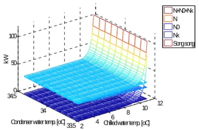
Fig. 3 Results of two chillers in series-series counterflow.
(a) Power surfaces as a function of the leaving water temperatures
water flow rate, so pumps power will reduce. On the other hand, chiller power will increase due to either decrease in the leaving chilled water temperature or increase in the leaving condenser water temperature with the assumption that either of the entering water temperatures is fixed. Total power of these pumps and chillers shows minimum.
2. Simulation program
The entering chilled water temperature, the entering condenser water temperature and cooling capacity of each chiller are fixed. In this study, the entering chilled water temperature and the entering condenser water temperature have been chosen as 12oC and 30oC, respectively, which are often chosen in air conditioning system design. And the program performs with 20 ton chillers and 15 ton chillers. Calculations are based on energy balance and heat transfer equations. The equations and the structure of the chiller system are not presented here for the sake of brevity.
3. Results and discussion
3.1 20 ton chiller
Fig. 3 shows results of two chillers in series-series counterflow. Fig. 3a presents power of chilled water pump, condenser water pump and compressor as a function of the leaving chilled water temperature and the leaving condenser water temperature in form of 3D diagram. The trends of power curves as a function of the leaving chilled water temperature are clearly shown in Fig. 3b. Increasing the leaving chilled water temperature increases the chilled water pump power but decreases the compressor power. So minimum power from total power curve is
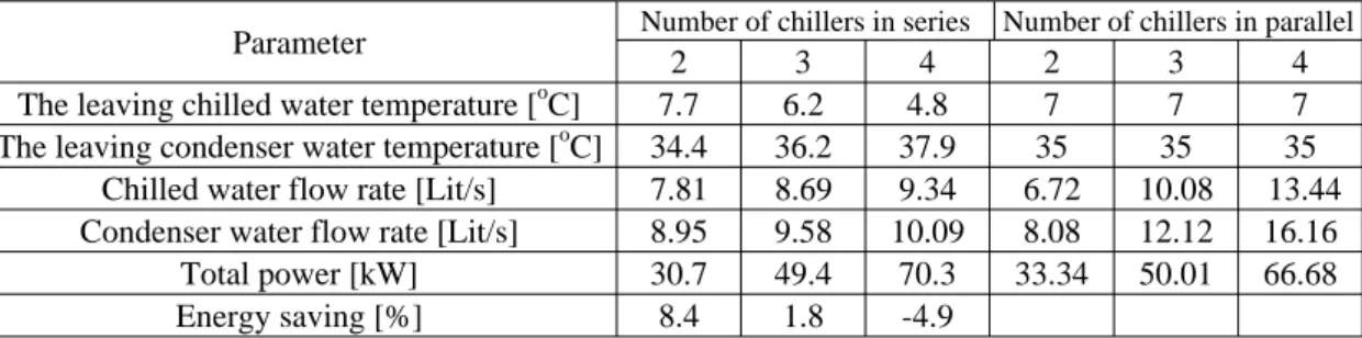
examined. The top line denotes total power of two chillers in parallel. In two chillers, the minimum total power in series-series counterflow is lower than that in parallel case. Through similar procedure with three and four chillers in series, table 1 lists the optimal parameters and total power compares with parallel case.
With increasing number of chillers in series, pumping power will increase rapidly, because pumping power is proportional to the cube of the flow rate. Meanwhile compressor power saving can not offset this rapid increase. Consequently, higher portion of energy saving is accomplished up to 3 chillers in series arrangement but for 4 chillers, higher total
Parallel case Total Compressor Chilled water pump Condenser water Pump
Parameter Number of chillers in series Number of chillers in parallel
2 3 4 5 2 3 4 5
The leaving chilled water temperature [oC] 8.4 7 5.7 4.6 7 7 7 7 The leaving condenser water temperature [oC] 33.5 35.2 37 38.7 35 35 35 35
Chilled water flow rate [Lit/s] 7 7.56 8.01 8.52 5.04 7.56 10.08 12.6 Condenser water flow rate [Lit/s] 8.42 8.55 8.52 8.61 6.1 9.15 12.2 15.25
Total power [kW] 22.3 35.5 50.1 66.23 26.4 39.6 52.8 66
Energy saving [%] 15.5 10.4 5.1 -0.35
Table 2 Comparison of power and the optimal parameters between series case and parallel case using 15 ton chillers
Parameter Number of chillers in series Number of chillers in parallel
2 3 4 2 3 4
The leaving chilled water temperature [oC] 7.7 6.2 4.8 7 7 7 The leaving condenser water temperature [oC] 34.4 36.2 37.9 35 35 35
Chilled water flow rate [Lit/s] 7.81 8.69 9.34 6.72 10.08 13.44 Condenser water flow rate [Lit/s] 8.95 9.58 10.09 8.08 12.12 16.16
Total power [kW] 30.7 49.4 70.3 33.34 50.01 66.68
Energy saving [%] 8.4 1.8 -4.9
Table 1 Comparison of power and the optimal parameters between series case and parallel case using 20 ton chillers
20 ton
15 ton 15 ton 15 ton 15 ton 15 ton 15 ton
15 ton 15 ton 20 ton 20 ton c. Case 3 b. Case 2 a. Case 1
Fig. 4 Three cases for 60 ton cooling capacity. power is needed in series arrangement.
In considering aspect of water flow rate, at three chillers, despite only 1.8% energy saving, water flow rate of series-series counterflow system is lower than that of parallel system, the chilled and the condenser water flow rate are lower, 13.8% and 21%, respectively. These reductions have significance for water distribution system, reduction of power in secondary pumps, for example.
3.2 15 ton chiller
The obtained results are listed in table 2. And trends are similar to those of 20 ton chillers case.
3.3 Comparison between 20 ton chiller and 15
ton chiller
In the previous section, we discussed 20 ton chiller and 15 ton chiller system separately. In this section, these two chiller systems are compared. For 60 ton cooling capacity, either three of 20 ton chillers or four of 15 ton chillers can be selected. Then, three possible arrangements are shown in fig. 4. The case 1 can be accomplished with the twice adoption of 2 chillers in series as show in table 2.
Fig. 5 shows total power and water temperature for those three cases at optimal parameters in each case. Total power of case 1 is the lowest (Fig. 5a). Otherwise, the water temperature difference of case 3 is not excessively unusual, the chilled water temperature difference and the leaving
0 1 0 2 0 3 0 4 0 5 0 6 0 3 4 ( 4 c h i l l e r N T N D ) 4 ( 2 c h i l l e r N T N D ) kW M ? n ? B o m n u ? c g i ? i n h i ? t B o m n u ? c l ? n h Compressor Cond. water pump Chilled water pump
Case1 Case2 Case3
8.4 37 12 30 36.2 6.2 33.5 5.7 0 5 10 15 20 25 30 35 40 1 2 Te mp er a tu re [ o C Case 2 Case 3 Case 1 Entering Leaving Chilled water Condenser water
(a) Comparison of total power
(b) Comparison of water temperature Fig. 5 Comparison of total power and water temperature among three cases. condenser water temperature difference are
5.8K and 6.2K, respectively.
4.
Conclusions
As control technologies continue to develop and some chillers allow leaving water temperature as low as 1°C without the aid of glycol, then the application of series-series counterflow chillers system with low-flow, low-leaving chilled temperature and highly efficient system in view of energy saving is one of the best solutions. Although energy savings are dependent on cooling capacity range, the system presented in this study can save energy up to 15%. An existing system can be converted to series-series counterflow system without more investment.
References
1. Groenke, S. and Schwedler, M., 2002, Series-series counterflow for central chilled water plants, ASHRAE Journal, vol. 44, pp. 23-29.
2. Hugh Crowther, 2002, Series Chillers - What's Old Is New Again, McQuay Engineering Solutions.
3. Susanna Hanson, W. Ryan Geister, 2005, International Cooling Projects Focus on
Series Chiller Plant Design: Changes in chiller technology make series chillers cost-effective, energy-efficient alternative. District energy magazine, 66.
4. Susanna Hanson, 2006, Saving megawatts with series-chiller plants. HPAC Engineering.
5. Simon Ho, 2006, Maximizing chilled water plant efficiency, EcoLibrium.
6. Donald Eppelheimer, 2003, Energy efficiency in North American district cooling plants. First International Conference on Energy Efficiency and Conservation, Hong Kong. 7. ARI Standard 550/590-2003. Standard for
performance rating of water-chilling packages using the vapor compression cycle.
8. Applications Engineering Manual, 2000, Multiple-Chiller-System Design and
Control. Trane Company,
SYS-APM001-EN.
9. McQuay, 2002, Chiller plant design.
10. John R. Thome, 2006, Engineering data book III. Wolverine tube, Inc.
11. Tran Thanh Ky, 2004, May lanh. VNU-HCM press.
12. Nguyen Van Tuyen, 2007, Tuabin hoi nuoc va tuabin khi, VNU-HCM press.