ISSN:1226-7244 (Print)
ISSN:2288-243X (Online) j.inst.Korean.electr.electron.eng.Vol.22,No.2,480∼483,June 2018
논문번호 18-02-35 http://dx.doi.org/10.7471/ikeee.2018.22.2.480
254
(480)
* Dept. of Railroad Electricity System, Woosong University
★ Corresponding author
E-mail: [email protected], Tel.: +82-42-629-6731
※ Acknowledgment
This research is based on the support of 「2018 Woosong University Academic Research Funding」.
Manuscript received Mar. 13, 2018; revised Mar. 24, 2018; accepted Jun. 8, 2018
This is an Open-Access article distributed under the terms of the Creative Commons Attribution Non-Commercial License
(http://creativecommons.org/licenses/by-nc/3.0 ) which permits unrestricted non-commercial use, distribution, and reproduction in any medium, provided the original work is properly cited.
I. Introduction
Wireless power transfer (WPT) [1] is the transmitting without the use of wires. There are two ways of transmitting the source power to the output load. One is inductive method and another is magnetic resonance method. At the beginning of the 20
thcentury, Nikola Tesla
developed a technique for a large scale wireless power distribution. For the past two decades, major developments were made in the field of microwave transmission. In 1946, William C. Brown invented wireless power transmission by using a rectenna, a rectifying antenna, converting microwave energy into
A Feedback Circuit of Effective Wireless Power Transfer for Low Power System
Young Hwan Lho * ★
Abstract
Wireless power transfer (WPT) is the technology that forces the power to transmit electromagnetic field to an electrical load through an air gap without interconnecting wires. This technology is widely used for the applications from low power smartphone to high power electric railroad. In this paper, the model of wireless power transfer circuit for the low power system is designed for a resonant frequency of 13.45 MHz. Also, a feedback WPT circuit to improve the power transfer efficiency is proposed and shown better performance than the original open WPT circuit, and the methodology for power efficiency improvement is studied as the coupling coefficient increases above 0.01, at which the split frequency is made.
Key words: wireless power transfer, coupling coefficient, wireless resonant frequency, power efficiency, magnetic resonance
---
A Feedback Circuit of Effective Wireless Power 255 Transfer for Low Power System
(481) direct current electricity.
The inductive method for a short charging distance is applied, but the magnetic resonance method was introduced at MIT in 2007 to transmit the 60 W power up to a medium distance of 2m.
II. Design of Wireless Power Transfer Circuit
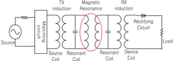
The equivalent circuit for the magnetic resonant circuit is shown in Fig. 1, which has the additional magnetic resonant coil to the original inductive circuit [2]. As shown in Fig.
2, the effective transmission depends on the high Q factor and coupling coefficient of k
Matchingcircuit
Source
TX induction
Source Coil
Resonant Coil
Device Coil RX induction
Rectifying Circuit
Load Resonant
Coil Magnetic Resonance
Fig. 1. A scheme for wireless power transmission using resonant coil.
Fig. 2 The efficiency vs. the quality factor (Q
L).
The value of k is ranged from 0.01 to 0.12.
Increasing the coupling coefficient leads to
enhancing the transmission efficiency.
Ⅲ. Simulation
The coupling coefficient has the range of 0 to 1. If the microwave produced at the source is all transmitted to the load, then the efficiency is 1. The efficiency is 0 for not transmitting it at all. The coupling coefficient [3] is defined by eq. (1).
(1) where M xy indicates mutual inductance between coil ‘x’ and coil ‘y’, Lx and Ly are inductances of coil ‘x’ and coil ‘y’, respectively, and the range of k xy is from 0 to 1. The relationship between the voltage and the current in Fig. 3 by using KVL is represented by eq. (2).
(2) Then, the load current of i
4is obtained by eq.
(3).
(3) Then, the load voltage of V
Lbecomes V
L= -i
4R
4and the power transmission efficiency of S
21is represented by eq. (4).
(4)
The magnitude of S
21is determined by the
coupling coefficient of k
23and the frequency,
256 j.inst.Korean.electr.electron.eng.Vol.22,No.2,480∼483,June 2018
(482) and the k
23is affected by the distance between the transmitting coil and the receiving coil. The mutual inductance decreases as the distance increases, in which the phenomena make the transmission efficiency be reduced and result in mismatching two coils.
In this paper, the equivalent open circuit of Fig. 3 [4] for wireless power transfer system is modeled, and the study of efficiency improvement is carried out.
Vs
Rs C
1 R
1
L1
i1 Power Coil
i2 C2 R2
L2 Transmitting Coil
k12 k23
L4 R 4
C 4 Load Coil
i4 RL
i3 R 3
C3 L3 Receiving Coil
k34
Fig. 3 The equivalent open circuit of wireless power transfer.
The power transferred to the load resistance of R
Lis changed when k
23is changed. For the feedback circuit (Fig. 5), the k
25is obtained through the coupling L
5for sensing the voltage across L
2.
The resonant frequency for WPT circuit is calculated using,
(5) The resonant frequency for each inductance and capacitance is computed as 13.45 MHz.
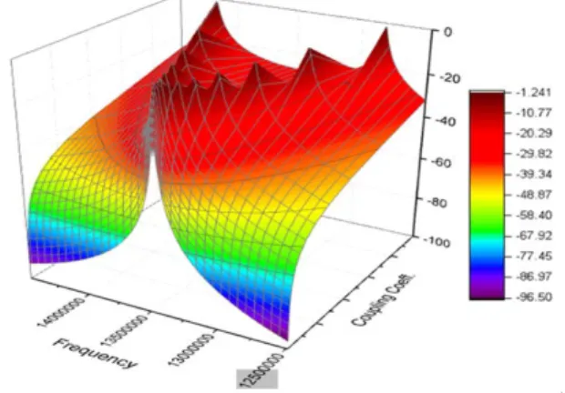
The inductance and the capacitance are 0.5 µH and 280 pF, respectively. The power transmission efficiency of S
21shown in Fig. 4 is calculated from 0.0001 to 0.1 by log sweep.
S
21increases as the coupling coefficient of k
23increases at the center of the resonant frequency of fo, which is 13.45 MHz, but the width of frequency is expanded and the
frequency is split from the coupling coefficient of greater than 0.01. For the coupling coefficient of less than 0.01, the resonant phenomenon occurs at the center of the single frequency. It is estimated that increasing k, namely the strongly coupling, can produce rather the reduction of efficiency for the short distance between two coils.
Fig. 4. The power transmission efficiency of S
21.
In Fig. 5, the value of k
23is estimated after measurement of V
L2. The variance of k
23affects the voltage of V
L2, having the corresponding resonant frequency fo±Δf. The oscillating frequency of the source voltage is adjusted to a new frequency of fo±Δf to make the circuit have a resonant condition in order to improve the power transfer efficiency for strongly coupled coefficient within the maximum allowed frequency of regulation. A new adjusted frequency for making the improved power transfer efficiency is created by the corresponding voltage for the feedback sensor inductor at the bottom part in Fig. 5.
Sensing the voltage across L
4after coupling
A Feedback Circuit of Effective Wireless Power 257 Transfer for Low Power System
(483) between L
2and L
5coils, and measuring the average voltage enables to change the input source voltage for the Feedback WPT circuit.
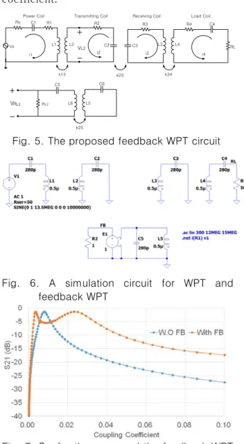
The blue line in Fig. 7 indicates the power transfer efficiency for the open WPT circuit and yellow line shows that for the feedback WPT circuit of S
21in terms of the coupling coefficient.
Power Coil
Vs
Rs C1 R1
L1
i1
L2 VL2 R2
C2 Transmitting Coil
i2
k12
C3 i3 R3 Receiving Coil
L3 L4
R4 C4
i4 RL
k23 k34
Load Coil
VRL2 RL2
C5 C6
L6 L5
k25